Will
-
Posts
159 -
Joined
-
Last visited
Content Type
Profiles
Forums
Events
Articles
Marionette
Store
Everything posted by Will
-
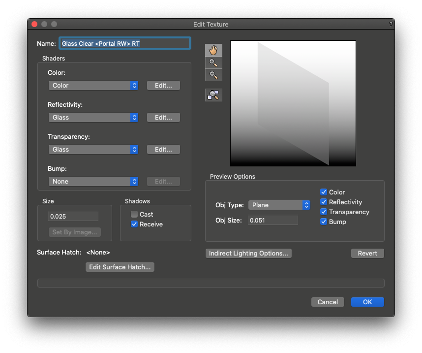
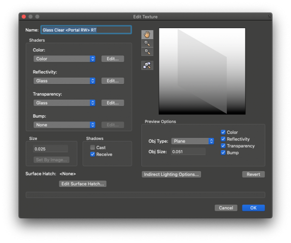
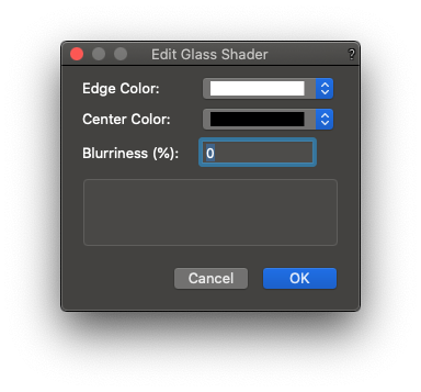
The texture is the unmodified 'Glass Clear <Portal RW> RT' Render texture that comes with vectorworks. I have also tried with the 'Glass Clear RT' texture and it has the same effect. Is SP2 generally available yet, I am on the initial release of VW and I just did check for updates but I don't see a new service pack yet.
-
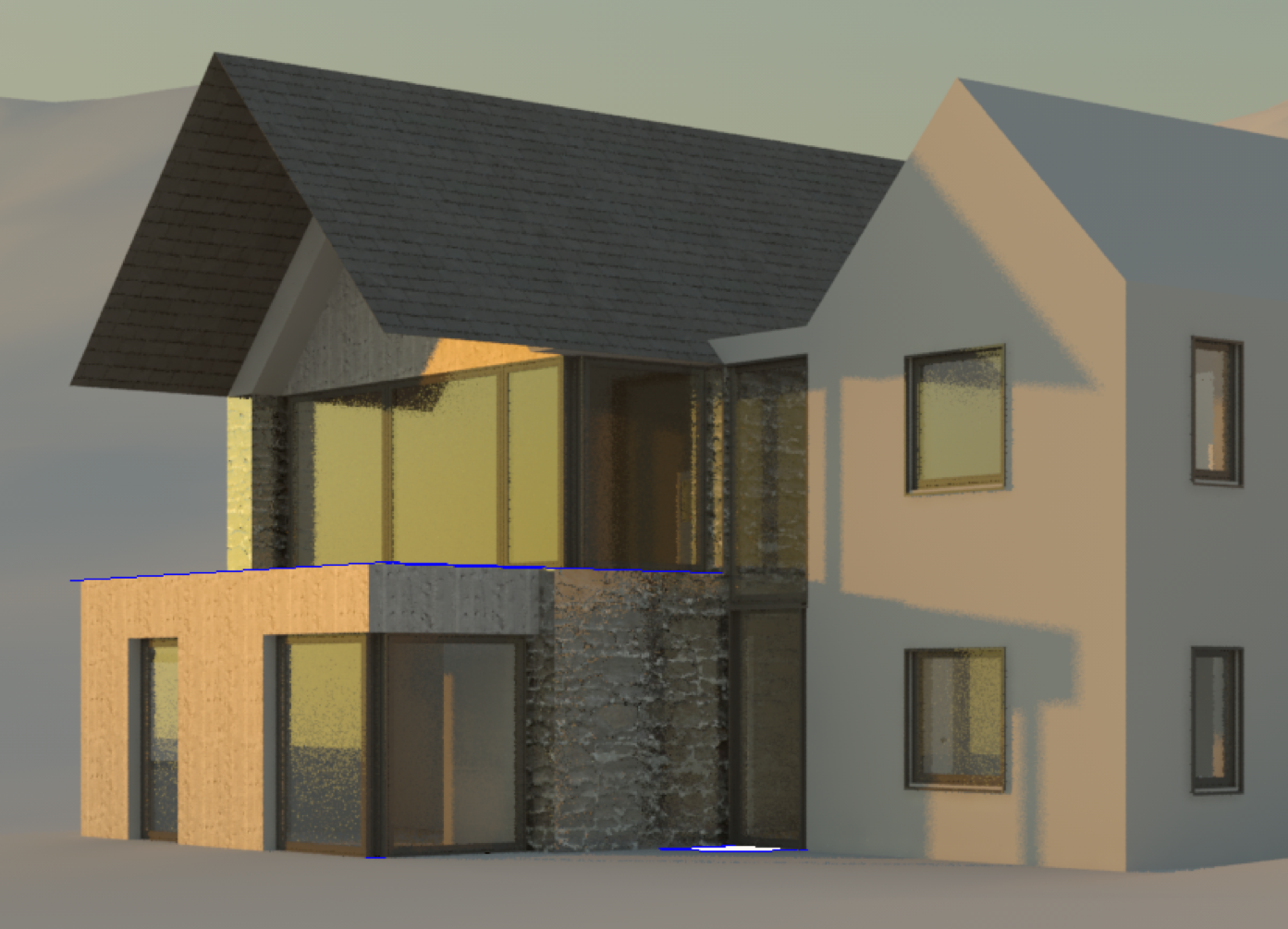
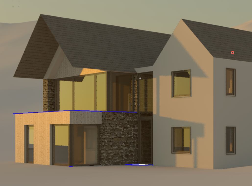
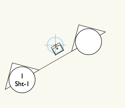
Hi I'm looking at migrating to 2021, but I'm having a problem with a degradation in rendering quality. This view is rendered in 2020: The next image is rendered in 2021, if you look at the glass you'll see a weird dappling and there is something strange going on with the lighting of the stonework. They are both rendered with the exact same settings. Are there any significant changes to Renderworks in 2021 that could explain this?


-
Tried it, doesn't work for me. Sometimes quitting and reopening vectorworks fixes it for a while, but on some projects it comes back really quickly.
-
@Tamsin Slatter Thanks! Ideally, rather than making us interrupt our work to go and hunt down and delete the rogue bit of drawing, I think it should be an alert that says, "Some geometry is further than n km/miles from the internal origin. It will not been shown and cannot be snapped to during 3d operations"1 as a modal alert first time, then as a minor alert in the message bar bottom right subsequently every time the user switches to a 3d view. From then on any stuff too far away is just ignored by the vectorworks graphics module when working in 3d. Sometimes it is unavoidable to have some things which are too far away from the origin e.g site mapping information, but they are almost never things that would be relevant in 3d so when working in 3d they could just be ignored by the system. 1 Where n would be whatever your programers calculate as the maximum the graphics system can cope with.
-
@Tamsin Slatter Hi Tamsin, thanks for answering. There might be some stuff in other layers, I will check. But could I make a feature request that the software detects this situation automatically and doesn't do the weird clipping. Best, W
-
Screen Recording 2020-01-08 at 15.39.23.mov Anyone know what to do about this? The project is centred on the drawing origin, user origin is set to (0,0). There are no objects in the visible layers that are far away from the drawing origin. Any other ideas how to stop it from doing this?
-
Hi @Matt Panzer, I filed a bug through bug submit back when I made my original comment, with an example file uploaded. Not sure I have a copy of the file in that state anymore, but it should be in your system somewhere.
-
Update on this for anyone else experiencing the problem. Export the file to VW 2019 open the file in VW 2019 then make a minor change e.g draw a line. Save the file. Re-open the file in VW 2020. Reshape handles are back. It is apparently a bug and they are looking into it.
-
I think it must be a file corruption bug @PVA - Jim as if I create a new file the reshape handles show up fine. Here is an example screen grab video. As you can see, its not my selection tool settings and it is really annoying when trying to work with site pad objects as you have to guess where the handles are for editing the slope. Why does this always happen to me when I'm trying to get finished for a deadline...😭 Screen Recording 2019-11-28 at 19.06.10.mov
-
Im also having this issue but only in one file. Very mysterious. Is it a document setting?
-
My wish: VW2021 to have no new features. Please.
Will replied to line-weight's question in Wishlist - Feature and Content Requests
And the weird moving external references bug which has been there for years. Triggered by moving the user origin or using rotated plan view, then close the file and reopen and boom! your external reference has jumped to another position. 2019-03-07_18-04-34.mp4 -
My wish: VW2021 to have no new features. Please.
Will replied to line-weight's question in Wishlist - Feature and Content Requests
Yes and the snaps that work in some contexts but not others. Why can I snap to intersections, line extensions and tangents when drawing or adjusting a polyline, but not when drawing or adjusting a polyline based object like a road? Likewise when drawing a line in 3d there are way more snaps available when drawing a line than when, say, adjusting a site model object or a wall. Why can't I grab the handle of something and get it to snap to a z axis locked intersection line with the face of a 3D object, but I can do this with a line. It's so confusing. -
My wish: VW2021 to have no new features. Please.
Will replied to line-weight's question in Wishlist - Feature and Content Requests
Yep totally agree with this list. Before they upgraded the title blocks I coded my own integrated with my own drawing issue system, issue sheets and automated PDF creation and collation. But we gave up on project sharing because our jobs are to small for it to be worth the hassle, so I don't know how well they would work with that. -
My wish: VW2021 to have no new features. Please.
Will replied to line-weight's question in Wishlist - Feature and Content Requests
Still poor general reliability. I've submitted about 6 crash dumps to bug submit in the last day and a half and experienced way more than that. Having a weird problem where VW sometimes randomly hangs while drawing 2d objects on planes in a 3d view. I had huge problems with generating sections yesterday where I could only get them to work by shifting them around until VW stopped crashing when I hit the update button. Not great. -
Can we have hidden line rendering done in a separate thread so we can carry on working while hidden line drawings are rendering. (I'm sure this must have been asked already but I'm obviously not using the right search terms. Please merge this thread if its been asked already)
-
Hi Matt, I tried to PM you. Not sure if you received the file?
-
Do you think that's something that might be in a service pack as there are often instances where a wall or component is slightly out. Is the tolerance tighter than the max decimal places (in degrees) we can see in vectorworks because I'm still having problems with interior elevation viewports. I've got a set of symbols with front and side 2d components and they are working fine in two out of 3 rooms, but my last interior elevation marker is not generating drawings with 2d components. I have switched on all layers and classes, verified that it is orthogonal to the max number of decimal places. I duplicated an interior elevation marker that I know is working in another room and checked the section lines, just not seeing any 2D components at all. Thanks W
-
Also, can someone tell me, is there a tolerance on how orthogonal the a view needs to be? E.g. If a toilet is on a wall that is at an angle of 30.002º and the interior elevation marker is placed at an angle of 29.999º is that going to work? I'm having real problems with some interior elevations not showing the 2d components. Thanks W
-
So I can recreate the problem by starting a brand new blank metric template. Draw a rectangle in plan. Create symbol based on the the rectangle. Switch to symbol front component, draw another rectangle. Create a section viewport on a sheet layer. Verify that the section shows the front component rectangle. Rotate the section cut line and the symbol by 30º. Verify that the front rectangle has disappeared. Results of this process are in the attached file. No data was imported, it was a fresh copy of an unaltered vectorworks supplied template and nothing more complicated than a rectangle was used. Seems like a bug in the 2d components feature to me? EDIT: But I'd really love to be wrong as I have a load of bathroom elevation drawings to knock out which I could have done in no time at all if I can get this working! Untitled 3.vwx Edit System specs. VW 2019 SP2. MacOS Mojave 10.14.1. MacBookPro Retina (Mid 2014) 2.5Ghz i7. 16Gb RAM. NVIDA GeForce GT 750M 2Gb VRAM.
-
Hi Tim, I created a new file from a standard vectorworks metric template, imported a dwg from a supplier, created a symbol from the plan view and then copied and pasted the front view into front view of the symbol. Should the front view geometry be on layer plane, 3d plane or screen? @Tim C.
-
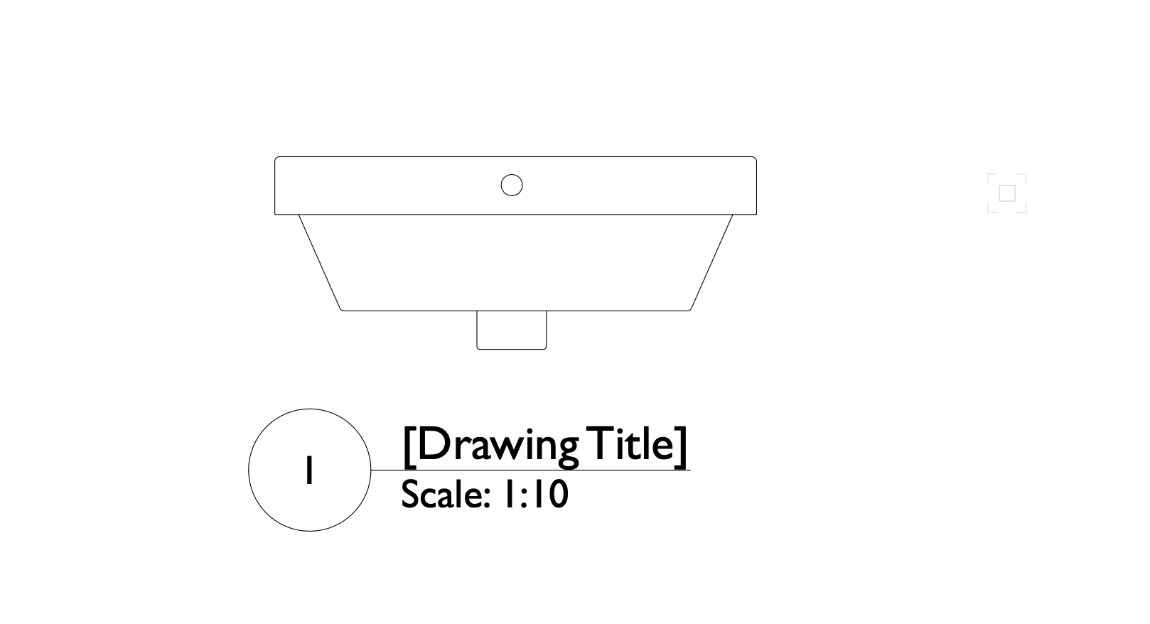
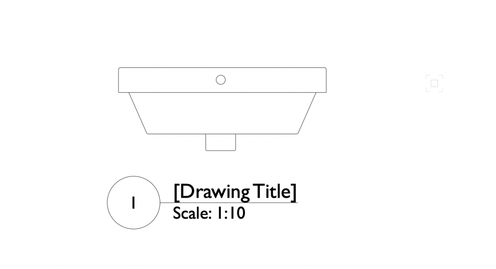
Hybrid handbasin symbol with 2D front view, in plan view: Heres the results of that section cut: Rotate both by 30º no other changes, here's the plan view: Heres the section view...uh oh were's the sink gone? Anyone got any ideas? Test file attached. Untitled 2.vwx


-
The best way to solve this would be to get rid of the concept of walls, slabs, roofs as different tools / objects. They are all composite plane objects built up of layers that need to interact with other composite plane objects at the edges. What I mean by composite is; built up from different materials in layers (called 'components' in the wall tool). What I mean by plane is objects defined by a plane like object or surface which could have an arbitrary boundary and holes cut in it. At each edge I want to be able to define if that edge is linked to the edge of another composite plane object and if it is how the layers (components) of object A interact with object B. Maybe you have a define connection tool which greys out everything and shows you a detail section where you can work all this out. Once you have worked it out for one edge, this could be stored as a favourite which would be available any time the same combination of two edges meet. While you are at it, can we have the ability to define repeating elements such as battens on layers in a way which preserves their orientation so they show up correctly in plan, but not section. Maybe just allow us to define an object which is repeating across a surface. The best bit would be that when the wall tool was improved, we wouldn't have to wait until next year for the corresponding improvements to the roof tool. So it would save a lot of development time as you would only have to solve the problems once.
- 1 reply
-
- 2
-

-
So far this seems to be fixed with SP1
-
Hi Matt I haven't received an email yet and I forgot to copy the number when I submitted. Best W
-
Yes no problem. By the way, I have already uploaded these two test files through bug submit yesterday.