


Luka Stefanovic
-
Posts
110 -
Joined
-
Last visited
Content Type
Profiles
Forums
Events
Articles
Marionette
Store
Posts posted by Luka Stefanovic
-
-
That's odd, for me it appears automatically and I don't have ti add anything in order to save an IFC file. As far as I know it's always been like that and I haven't heard about this kind of issue. Let me check whether there is a setting that might control this and get back to you.
-
 1
1
-
-
@Mitchell (the other one) I would recommend using Door Styles as they would represent a type of Door with exact same parameters that would be used throughout the project - ie bathroom door, bedroom door etc.
In my opinion, symbols come in handy in case of bespoke/custom Door geometry that can't be achieved with the Door tool (ie doors on a church with intricate detailing and gothic arches). In that case, you would model it, save as a Symbol and use that instead. You would lose parametric control over things like Use Wall Depth like you say, but that's why I would only resort to Symbols if I can't achieve what I want with the Door tool.
-
@matteoluigi When you go to export IFC project you can choose the file format with a choice between .ifc, .ifc (zipped) or .ifcxml and when you click Export button it will automatically add .ifc (or other as chosen) extension to the file name in the Save As... field. Just make sure you don't delete the extension if you are changing the file name and it should be OK.
-
ThermalTransmittance is the way to go with this - you can map the Style U-Value in Data Manager. Have a look at default settings for Walls under ifcWallStandardCase Pset_WallCommon as Pat mentioned. You can use the same analogy and map U-Values for Slabs, Doors, Windows - any object that has a Style and a U-Value.
You can then use this data as display criteria for Data Visualisation, but remember you can only display one criteria per viewport, so Slabs would need to be separate from Walls for example. Perhaps you can overlap viewports but not sure how that would look like.
See attached an example showing Data visualisation of Slabs by U-Value
-
1
-
-
Depending on your requirements, if you want some more detailed calculations you can attach Energos Window Record Format to the Rooflight Symbol, and you can use the Window object before converting to group to extract the values to populate the Record Format so the Energos calculations will be more precise in that respect
-
Hi @drelARCH
Good to see the issue being solved, thanks @Nikolay Zhelyazkov Can I just suggest a workflow to this - I would create the Rooflight using Window tool (as close as you can get to what you're trying to achieve), then Convert to Group and create 3D Symbol. You can then access this Symbol through Resource Manager and attach a Record to the Symbol definition, and Edit Values so you can actually input U-Value and other fields in that Record Format so when you insert the Symbol they will be populated automatically.
-
2
-
-
@Kazemester Finally! Great to hear that and glad we solved it. Have fun with exploring Data Manager workflows
-
1
-
-
@Kazemester Hard to say what's going wrong without seeing the files. One thing that comes to mind is that mapping in Data Manager is for Class based objects, so when you create Extrudes using Modify by Record they will be created on active Class. If that is not the same as the Class you mapped data to, it won't work. If it still doesn't come through, try mapping in the Data Manager after you've extruded the Polygons making sure the objects are on correct classes, perhaps that will do the trick.
Let me know if you manage to do it.
Good luck!
-
1
-
-
@Kazemester sorry about late response. See the attached video - is that what you are looking for? Hope it helps and the video is clear.
Let me know if you have further problems in getting the Ifc data across.
-
I agree that you could run these calculations in worksheets too, however this would be a very manual process and would require a lot of setting up by someone who knows the subject very well. Benefit of having a tool like Energos is it becomes an automated and streamlined process that can be used by Architect who are not necessarily experts in setting up the formulas themselves.
On 4/22/2020 at 8:48 PM, Samuel Derenboim said:you cannot extract certain information from energos like exterior wall surface area, interior wall surface area
I think you're looking at the wrong place here. I wouldn't try to extract these values from Energos, I would use worksheets. Output of Energos is things like Heating loads, Energy demands, Overheating etc. Sure, it uses things like Exterior/Interior wall surface area to get to those outputs, but they are a means to a different end. It's not a limitation, even more so as you can get those surface areas in a report.
On 4/22/2020 at 8:48 PM, Samuel Derenboim said:I used grosswallarea_net versus Component net area and it had a difference of 6 - 8%
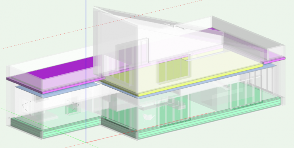
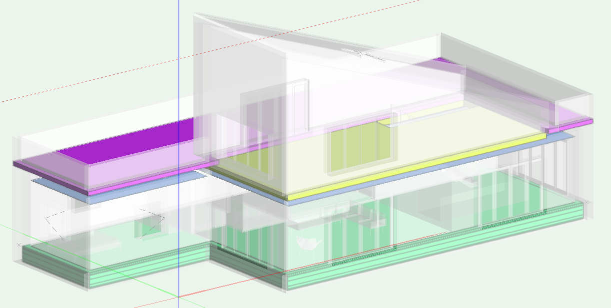
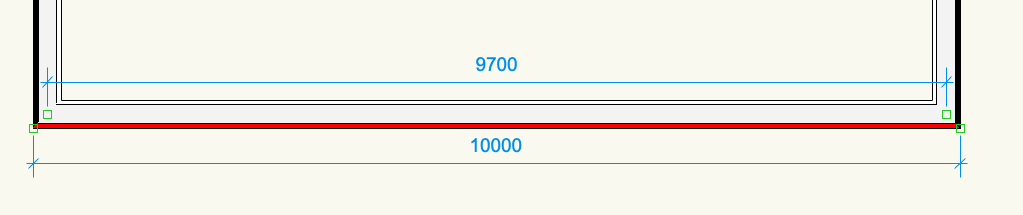
WALLAREA_GROSS and COMPONENTAREA(n) will give different results because the first one will give the area of the wall based on the wall centerline and wall height, and the other will display the surface area for Component n. In an example of a 300mm thick, 10m long, 3m tall wall with two corner joins with other 300mm walls WALLAREA_GROSS will be 29.1m2 but the COMPONENTAREA for outer component (red in image below) is 30m2
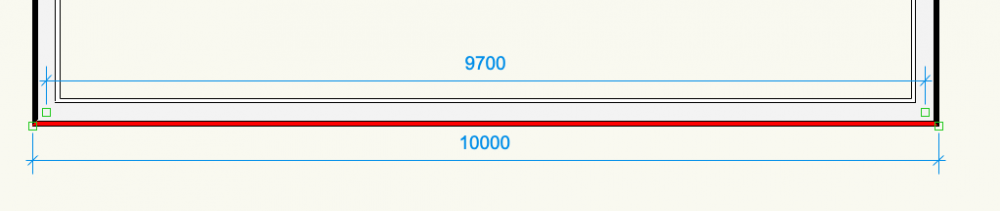
WALLAREA_NET will instead return WALLAREA_GROSS minus any recesses or openings.
I will be looking more into wall surface areas and how they are calculated in Vectorworks and in Energos, including corner windows, curtain walls and There are a number of functions which you can use to extract different quantities using Worksheets, it's a matter of choosing a right one to get to the corrrect numbers! Hope this helps and clarifies the issue.
-
2
-
-
On 4/19/2020 at 3:52 AM, A McDonell said:
I want some space by space energy demand control- for instance the boiler to not be heating some circulation and storage spaces... how would i achieve this?
You can exclude individual Spaces by unticking Use in Edit Spaces List. This will update the Total Relevant Floor Area
-
2
-
-
On 4/19/2020 at 7:31 AM, A McDonell said:
why doesnt curtain wall have any energos settings? this seems like a major problem
Edit curtain wall style insertion options tab has Include in Energos Calculations greyed out. This is because Energos settings are located under Frame and Panel settings and type of frame and glazing can be set from a customisable list with parameters.
Thing to bear in mind is that for frames this needs to be set for vertical, horizontal and all boundary frames individually.
-
3
-
-
- Popular Post
- Popular Post
Hi everyone,
Bit late to the party, but I'll try to chime in and add to the conversation. I'll also reply to some of the queries raised previously in separate posts, but it might take me a while to go through the thread.
My general view is that Energos is a fantastic tool for Architects to understand the energy performance of their design and to do so throughout the design process. I feel sometimes users expect it to be something that it’s not - energy modelling software. Vectorworks is, as you know, a Design Software (in this case we're talking about Architectural Design) and Energos has been developed as a supplement to an Architects' workflow, not as a replacement for the likes of IES. It's based on mathematical calculations using PassivHaus methods - this is what enables it to update the results and recalculate in a matter of seconds instead of much longer times that would have been required if it were modelling the solar path and geometry to calculate shading for example. Instead, it relies on Designers' manual input to determine shading percentages for each opening, which requires either a manual detailed calculation in order to input an accurate percentage value or leads to some minor inaccuracy.
To summarise, I think if accepted for what it is, a very useful and in-depth energy performance evaluation tool to accompany your architectural design process from the very beginning, then it has a real value to Architects and gives them power to make informed design decisions at every step in that process do they can create truly sustainable and energy efficient architecture.
-
5
-
@Kazemester I've just tested the workflow as I described above and it works for me... Can you send me the file with 2D polygons that have Record Formats attached to them?
-
@Kazemester When you map the data from a Record Format to a custom Ifc pSet, you should be seeing actual values from the individual object, not the defaults from the Record Format
-
Next step would be to use the Data Manager to map the data from the Record Format to Ifc psets - the key here would be to have all of these Extrudes on the same class. Then you can use the Class-based objects in the left pane of the Data Manager - add the class that the Extrudes are on, then in the middle pane add the Ifc Data Set you wish. Final step is to define Data Mapping for the Data Fields in the Ifc Data Set and link those with Simple Formula using Initial Field value as Record Format and then select the field you want to map to.
I hope this makes sense, but let me know if it works or not and I can try to explain better if needed.
Good luck!
-
3
-
-
@Kazemester I'm trying to understand how are you extruding the 2D Polygons? If you are using the Model > Extrude command it will essentially create a new Extrude object. If you edit the Extrude you will see the 2D Polygon with the Record still attached to it, that's the reason that the Extrude does not inherit the Record Format.
If you follow what Tamsin has suggested, and use Modify by Record command, the Record format will be preserved and it will be attached to the Extrude object. I suggest creating a dummy field in the Record Format which you would populate by the extrusion height and use that field for Modify by Record.-
1
-
-
Hi @KIvanov
Thanks for the update and for the fix. Hope this solves the issues and enables the users to tag smoothly while using project sharing.
-
1
-
-
I'm not sure when the fix will be available, I will check with the engineers.
I will add your comments to the bug report for the engineers to see.
Can you please confirm which version and build are you on?
Thanks
-
22 minutes ago, Amorphous - Julian said:
Also, after save and commit, we lose all data in all tags.
This is an issue we are aware of and are working to find a fix. There is a workaround however, if you check out the Data Tag AND the objects they are tagging, then the association will remain. The associations are lost after Save and Commit if only one of the two is checked out.
-
13 minutes ago, Amorphous - Julian said:
What does 'definition of a symbol' refer to?
Symbols save objects for reuse, essentially as smart copy/paste. The objects are incorporated into a symbol definition, which is a resource that can be selected from the Resource Manager. When a symbol definition is placed into the drawing, a symbol instance is created. If you attach something to an instance only that instance will have that, as opposed to attaching it to the definition when every instance will have it.
-
4 hours ago, Amorphous - Julian said:
it turned out the issue was leaving the referenced 'Survey' layer (DWG linework) hovering over our 'Proposed GA' layer in the viewport, which contains the wall objects
The Data Tag will only work with objects that have the data set that it's picking up the values from - that is why you had the dialog saying 'Current Data Tag requires the following data to be attached to the symbol' - apparently you were trying to tag a symbol, not a wall. It also gives you a choice to tag an instance or a definition of a symbol.
For example if a Data Tag is picking up Width value from a Door style, it will only be able to tag Door objects, you would need to set up another one for Windows, or if it's a Record Format, there needs to be one attached to the object you're trying to tag.
-
Hi @Amorphous - Julian ,
I've been away for a couple of days so haven't been able to respond. Glad to see issues being sorted though.
12 hours ago, Amorphous - Julian said:INT([Component.Thickness])
👍This is the way to do it. I think you can also add a dimension suffix to the formula too - just mm or " at the end after brackets should do the trick.
-
@_James It will work on a Mac as Chorus is as you say cloud based and in a browser. Previously we were not able to integrate with them because they had only Windows based plug ins, but now they had gone browser based you will basically be able to open the browser from within Vectorworks and log into your Chorus account to link the Spec to the model
-
1
-
ENERGOS 2020
in Energos
Posted
Thanks @Mark Stephens for pitching in on the thread and sharing your thoughts on Energos.
It's a very good seminar, I would definitely recommend taking some time out to watch it, there is much to learn on Passivhaus design and Energos.
Luka