


Chris Burton
-
Posts
39 -
Joined
-
Last visited
Content Type
Profiles
Forums
Events
Articles
Marionette
Store
Posts posted by Chris Burton
-
-
Has something changed where only certain palettes are able to be docked? The Basic, Tool Sets, Navigation, and Object Info palettes dock normally, but for the life of me I cannot get the Attributes palette to dock anywhere.
-
Alternatively, aside from the BW webinar that starts with the demonstration of how to link truss pieces, are there any other Braceworks-specific training videos?
-
4 hours ago, Nicolas Goutte said:
Yes, you can do that. Activation will work too. You can just not run both Vectorworks exactly at the same time, but just alternatively.
(To be sure check that the 3rd letter of your serial number is X. However as far as I know, platform-depedant serial numbers have not been issued for years. see this article from Jim Wilson:
)
Thanks very much Nicolas!
-
I've watched the 'inserting truss' tutorial, but am wondering if there is something similar for attaching lighting instruments to trusses.
I'm currently trying to figure out the best way to take a lighting plot, that is sent to me with straight truss, and replace that truss with a particular type of truss (insert truss) while having all of the lighting instruments attached to the new truss. Adding the truss and hoists is easy, but I don't know where to go from there so far as getting everything attached so that I can calc the rig.
thanks,
Chris
-
I know that one license allows you to install the software on two different machines, but can those machines run different operating systems?
I ask because I currently have a Macbook and am thinking about buying a MS Surface Book 2. At least for a little while, I'd like the ability to run the software on both machines.
if it matters, I am in the U.S.
thanks,
Chris
-
22 hours ago, Pat Stanford said:
Pulleys come in stock sizes, Belts come in standard lengths. In a 3 pulley setup as shown, at least one of the pulleys has to be adjustable so that you can loosen it to remove an old belt and put on a new belt.
2D version of Shrink Wrap would be the Lasso mode of the polygon tool. It will have to be redone when you change the pulley locations.
Set the Tangent snap on and draw lines between your three pulleys.
Select the Lasso mode of the Polygon tool and draw a "fence" completely around the three pulleys. You will get a new polygon created that is the interior portion of the pulleys and the lines. You can extract the perimeter from the OIP.
I tried to use the Tangent constraints, put they don't seem to work properly when I move the pulleys.
You could write a script that would do this. My rough estimate is that it would take me about 4 hours to write and debug this. 1. I don't have 4 extra hours in my life right now. 2. It would take someone without lots of scripting experience 2-10 times longer to write the script. 3. How many times are you really going to have to move the pulleys and how much time are you really going to save by having a "faster" way to do this?
Thanks Pat. I'm only ever going to do this once. It was more of an exercise for me to expand my Vectorworks 'skills', which are pretty rudimentary at this point.
-
In the search through the web, I came across a German company that has a free piece of software that will calculate belt length for multiple pulleys.
I ran the pulleys & dimensions through it that I have in my vwx file and it was close to the same result. The linked software uses metric dimensions and the bely length it calc'd was about 1cm longer than what the vwx files comes up with. Vectorworks shows 869mm whereas the Mulco software came up with 879mm.
fwiw,
Chris
-
3 hours ago, Gadzooks said:
Nice sheet @Chris Burton
I see the problem - I don't think this can be down to (say) rounding - there must be something obvious (surely?)
You've checked the originator's derivation? Although nobody on that forum seemed to have found fault.
I've a had a cursory look but I can't see anything glaringly obvious. I'll have more time later. Meanwhile someone far better than me will surely step in.
This would be like a 1 minute brain teaser for @Pat Stanford (if you have time Pat)
I'll spend some time with it today, but first I'll have to learn some math in order to check the derivation. After I thought I had it completed & functioning, I went back through it a few times, finding a mistake here and a mistake there, so I wouldn't be surprised if the error still sits on my end. It'll be a cool sheet if it eventually functions correctly.
-
3 hours ago, Gadzooks said:
Often the 'simplest' way is to Google the question and see what the (sometimes quite varied) answers thrown up are. There aren't many questions these days where you're asking it for the very first time (unless you're Stephen Hawking - RIP Stevie)
So, the first answer I get is this.
http://electromotiveforces.blogspot.com/2012/04/equation-for-determining-belt-size-of.html
Looks ok? Also looks like you could quite easily transfer the calculation to a VW worksheet with the primary distances and pulley diameters (the 'given' figures) fed in automatically from the drawing. There are others on the web, but I didn't look further. Once you get into whether the belt is 'Vee' etc, I got 😐
You may even find someone will provide you with that worksheet! - there's some mighty benevolent guys on this forum.
Hope this turns out useful for you.
Thanks for the link. I'm working through it with Excel, but can't seem to get it to mesh with what Vectorworks returns.
-
 1
1
-
-
5 hours ago, Gadzooks said:
I'm not sure you can in this scenario B.
Yes, that would enable you to 'grab' and move the three point contact area with the pulley - which is a very useful option on this tool when the geometry is consistent and just needs relocating. I don't think its as easy as that in this instance, as the geometry changes when the pulley(s) are moved in relation to each other and reshape tool doesn't have the finesse required to incorporate the reshape of a small section all in one action.
My take on this....
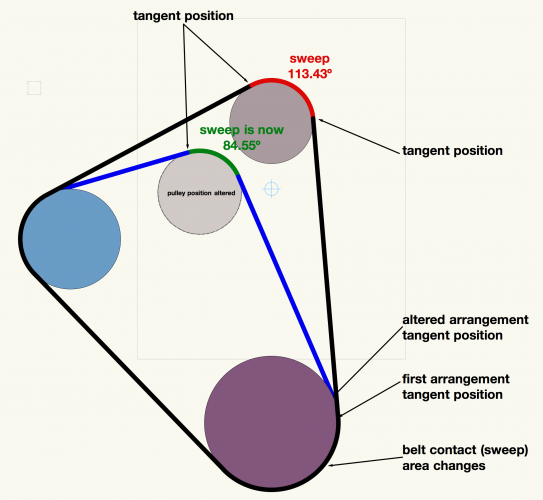
So, the repositioned pulley has obvious and immediate changes to belt contact, and the changes also affect the 'fixed' pulleys.(I've only pointed out the lower larger one)
Or have I missed something and I need more coffee this morning!!
(prob need more coffee anyway 😴)
5 hours ago, Gadzooks said:Gadzooks,
That's correct. That's what I'm trying to figure out how to do (in the 'simplest' manner possible).
thanks,
Chris
-
59 minutes ago, Gadzooks said:
Yes I remember (hate to admit it)
There were some teaser files with moving gears and cranks (the files - not me). In those days the simulation was achieved by scripting - something available today and still works (as not much has changed in scripting). The scripts have ©1997, Diehl Graphsoft, Inc. Developed by Tom Urie on them.
These days you'd probably be directed towards Marionette for the way to achieve this, but here's an old thread on that sort of track...
Shows most stuff is possible!!
Also shows theres clever guys on this forum
Thanks very much.
Chris
-
-
Hi,
I'm brand new here and am not sure where to ask this, but...
I have a few questions related to this file. It's supposed to represent three pulleys and a belt on the front of a car's engine.I'd like to:
1) make the lines that represent the 'belt' one single line. Is there a way to combine the six pieces that I have, or is it better somehow to draw it as one line from scratch? I couldn't figure out how to do that accurately.
2) and then is there a way to dimension the length of the 'belt'?
3) bonus question: is there a way to 'attach' the belt to the pulleys so that the belt is resized as the pulleys are moved closer/farther apart?
FWIW, I use vwx as a rigger, so I'm familiar with truss, motors, lighting fixtures, and such. Drafting, not so much.
thanks,
Chris

Vwx 2021 docking the Attributes palette
in General Discussion
Posted · Edited by Chris Burton
Thanks for your reply. I just undocked all of the palettes and tried again. They all dock normally, except for the Attributes, which will not dock anywhere.