Alex Weston
-
Posts
3 -
Joined
-
Last visited
Content Type
Profiles
Forums
Events
Articles
Marionette
Store
Everything posted by Alex Weston
-
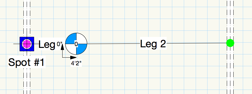
I've been grappling with this for some time and have had no success thus far. Whenever I change the Hoist Label Measurement Position in either the OIP or the Hoist Tool preferences, Vectorworks performs some math I don't understand and returns consistent, and unwanted results. The original positions are 1'4" for both X and Y. If I enter 0"0" for X, -3'10" is the consistent result. If I add 3'10" to that figure to put it back at 0, it stays at -3'10", if I add 10'0" it goes to 2'4". Similar with the Y position, except the value is -11'10". That's some cool math, but I don't understand it. The same figures show up when I try to set the values in Hoist Tool Preferences. Moving the labels with the handles works, but is tedious. Also, on a similar note, is there any way in 2022 to set a preference for where the Hoist ID is positioned? Centered on the Hoist would be my preference, but the default seems to be outside the symbol, to the lower right side. Most of the rigs I work on have points close enough together that having the various labels so spread out interferes with legibility. Hang on a moment... I just tried, and was able to successfully set my labels where I wanted them in a brand new, -blank- document. Perhaps there is some corrupt bit of preferences lurking somewhere in the template I am using? If so where, and how to delete -that- and start over without having to recreate the entire template? Alex Weston
-
Sure, I started to do that too. They ended up evaporating when I clicked on update in the Manage Bridle Parts dialog...
-
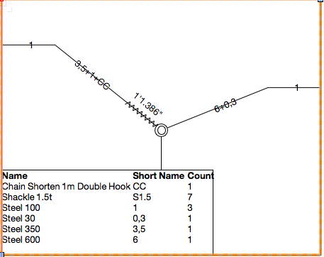
I find the direction Vectorworks is heading with incorporating rigging tools to be very promising. Perhaps not perfect, but heading in the right direction and getting better each year. For me personally, I would like to be able to have the bridle legs made with steel labeled with industry standards...ie 5' 3/8" Steel, 20 ' 1/2' steel...etc. Steel 200 isn't particularly useful...when I've changed it in the Manage Bridle Parts it has reverted back to defaults rather than keeping the changes I made. Am I missing something? Another thing I would like to be able to customize is how the bridles are built in the Create Bridle Diagrams tool. In a couple of the tests plots I've made the some of the bridles were built with three STAC chains...including one on the down leg! Nobody wants to make or pull that bridle up! Some industry standard language like a 15/20 bridle with 4 working links on the 20 leg, 5' baskets and the Deck chain between the basket and the leg would be appreciated...I have yet to see how to customize the rigging options to provide that kind of information. The only tutorials I've seen are the brief videos in the "whats new in 2019" area, does anyone know of more detailed tutorials? Thanks, Alex