


Sebastian Giese
-
Posts
18 -
Joined
-
Last visited
Content Type
Profiles
Forums
Events
Articles
Marionette
Store
Posts posted by Sebastian Giese
-
-
Hi all,
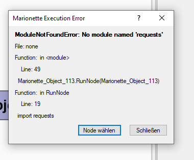
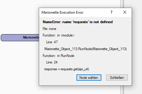
i created a network to assign objects to classes, fairly simple. I used the Node "Get Record Field" to get information about the objects. As a Marionette network it works like a charm, but when i save it as a script and execute the script, i get the following errors:
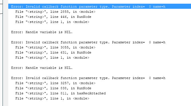
and a lot more in the same style.
I inspected the given lines in the script and found around the indicated lines following code lines in the node "get Record Field":
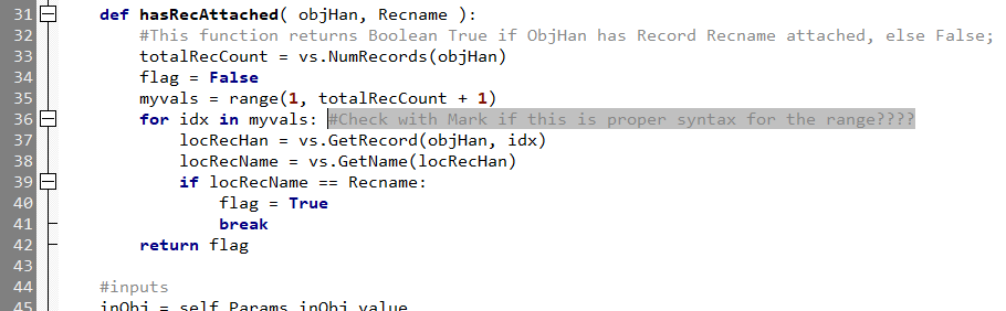
This looks like this node is not correctly working and the developer should talk to Mark?? 🙂
The node is #Modified by MFarrell May 2017
Attached the script and the network.
Cad anyone help with the node or the script? Or anyone have a newer version of the Get Record Field Node? Ooooor anyone have a different idea?
-
Can i please get the document too?
-
Hi,
i would like to see the available amount of equipment in a table column, like this:
Symbol Name | plannend symbols | avaliable symbols in equipment list
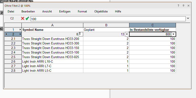
I can't find the correct syntax for the table. can anyone help?
-
Hi everyone,
inventory lists looks nice, but I have to click through EACH symbol definition INDIVIDUALLY, there is no multi-selection. Thus, the inventory list is useless, as no one clicks through hundreds of symbols individually.
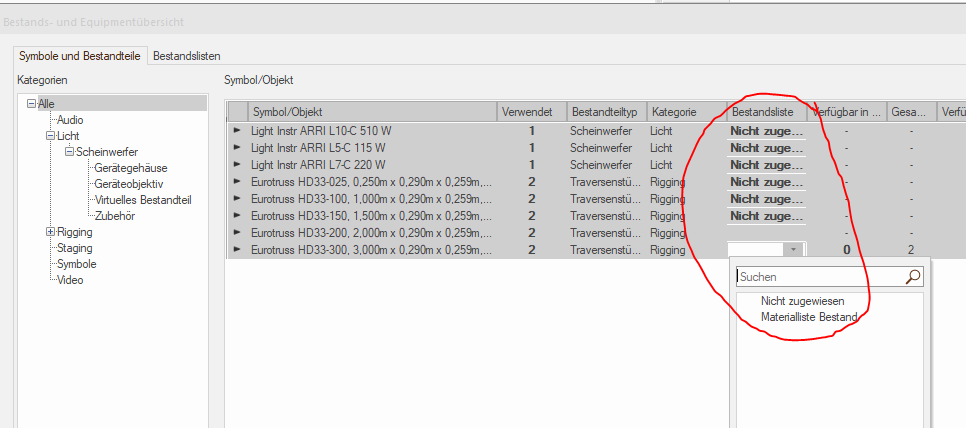
Also, in this dialog, it is not possible to assign multiple symbols at the same time.
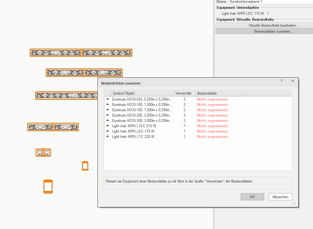
Am I overlooking something? Can someone reproduce this?
-
The Hoists A1 and A2 (Hoist 1/2 Ton CM ProStar) seems to be corrupt. When calculating i get this failure message:
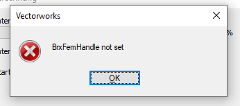
Change the two hoists and the system is correct:
-
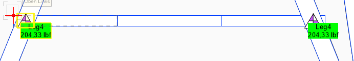
Hoist 2B-9 is not connected (or other failure), so the system is not symmetrical.
-
@Antonio Landsberger Can you help me? Do you have any suggestions?
-
Hi,
rightklick on the Trusssymbol in ressource manager, edit 3D, then rotate 3D geometry 45°.
The attached screenshot show the symbol in Top Plan view and in 3D view.

That's the Top Plan View after regenerating the 2D view of the symbol out of the "new" 3D object orientation.
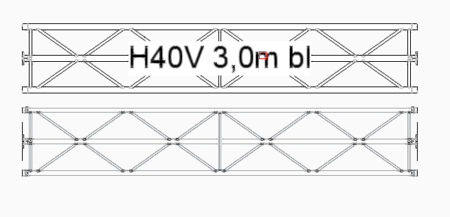
By the way: could you send me the load charts for this diamond configuration?
-
@Antonio Landsberger
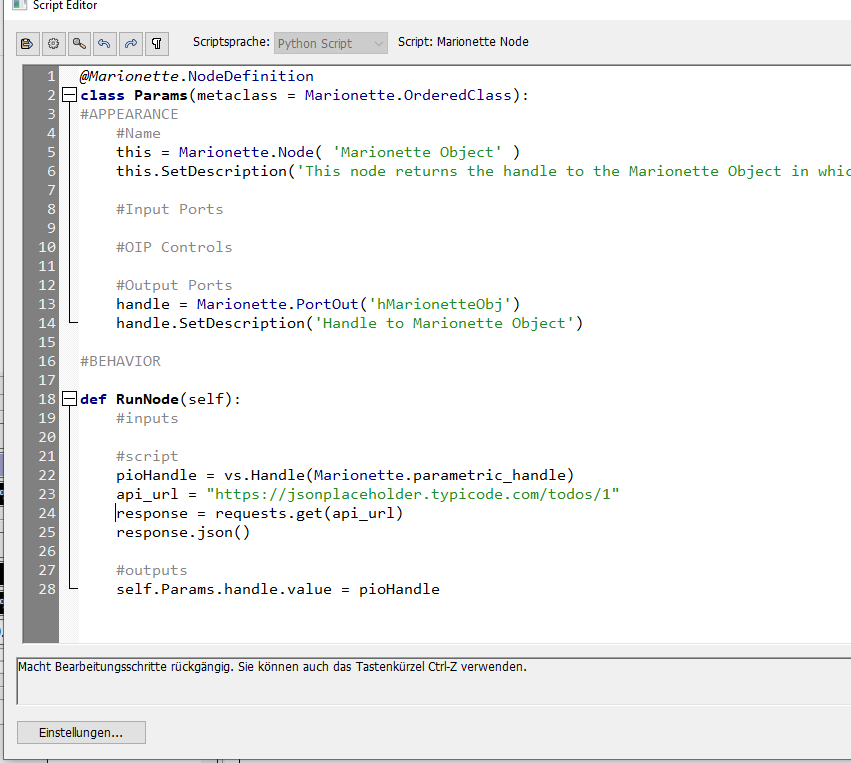
I tried every possible position for the string "import requests", none of them works:
Part 2:
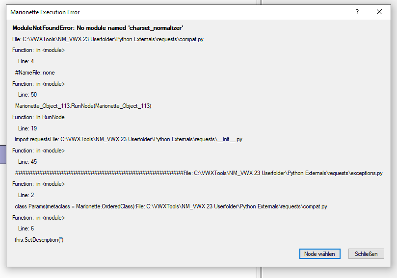
When installing the package with PIP and copy the installed package into the Python Externals Folder, the import works, but the module don't find somehting like "charset normalizer"
-
Hi, thank you, i know this python package but can't implement it into marionette.
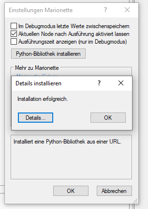
Installation in VWX works, but i can't import it in a node.
-
Hi @DomC,
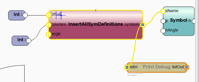
ich habe diesen Code eingefügt, leider ergibt der Node keine Symbole... Ich komme leider nicht drauf wieso das nicht funktioniert?
@Marionette.NodeDefinition
class Params(metaclass = Marionette.OrderedClass):
	this = Marionette.Node( "InsertAllSymDefinitions" )
	this.SetDescription( 'Shows all Symbol definition' )
	offset = Marionette.PortIn( (1), "offset" )
	offset.SetDescription( "offset of columns and rows" )
	columns = Marionette.PortIn( 4 )
	columns.SetDescription( "Number of columns" )
	angle = Marionette.PortIn( (0) )
	angle.SetDescription( "angle" )
	symbols = Marionette.PortOut()
	symbols.SetDescription( "the created symbol preview" )
	this.SetLinksObjects()

def RunNode(self):

	versatz = self.Params.offset.value
	spalten = self.Params.columns.value
	angle = self.Params.angle.value

	x=0;y=0;zeile=0;c=1

	symnames=[]
	res_list,num_items=vs.BuildResourceList( 16, 0, '')

	for i in range(num_items):
		res=vs.GetResourceFromList(res_list, i)
		if res !=vs.Handle(0):
			t=vs.GetType(res)
			if t ==16:
				symnames.append(vs.GetName(res))

	#vs.AlrtDialog(str(symnames))

	for n in symnames:
			vs.Symbol(n,x,y,angle)
			vs.Locus(x,y)
			x=x+versatz
			zeile=int(c/spalten)
			y=zeile*versatz
			if c % spalten ==0:
				x=0
			c=c+1

	self.Params.symbols.value = vs.LNewObj()
-
Hi all,
anybody succeded in creating a network for sending JSON to an REST API?
-
Hi all,
I have a referenced viewport to an external file, the viewport is cropped with a rectangle. When using the 2D top view, everything is nice. When using any isometric view or rotating the view, the boundary remains (because it is drawn on the "screen plane") and thus shows me some section of the reference, but never the one I had selected in the 2D top view.
Unfortunately, meaningful work with view limitations in 3D is not possible.
I tried the following:
- Draw boundary in "Construction Plane Orientation" from the start. But it doesn't work because the option is grayed out.
- Changing the orientation afterwards doesn't work either, I can select the orientation in the info palette, but it doesn't change.
What options are there for still working with 2D/3D plans as a referenced cropped view with without being completely lost when rotating in 3D space?
My workaround would be to insert the view on two layers, one layer for 2D top view (with viewport crop) and one layer for 3D views (without viewport crop but with clipping box). When changing from 2D top view to 3D views, the respective layer must be selected each time. I actually wish for a section box which also "cuts" in the 2D top view or alternatively a boundary which also works in 3D.
Any thoughts?
-
Same here and no good workaround. The only way is to CTRL-X, move truss and CTRL-V… the tool „dettach loads“ is not really an option, because you have to klick on every single object attached to the truss, twice.
-
The VWX Plugin https://www.production-assist.com can show different settings of structures over a timeline, besides a lot of other cool (rigging) stuff (e.g. structural calculations of ground supports). The basic version is free.
best regards from berlin
-
 1
1
-
-
Did you hit the update/refresh button after you changed the settings?
Node "Get Record Field" produces error when saved as Python Script
in Marionette
Posted
push