Martin d
-
Posts
14 -
Joined
-
Last visited
1 Follower

-
I never found one, the project timescale was too tight so I had to move on which was frustrating. The issue may have been fixed in the new release but I'm not sure. Our issue was that we had cladding zones directly above low level glazing. On plan this was projecting as being overlayed whereas we wanted the cut plane to be within the window glazed zone. What we ended up doing was creating a set of high and low level layers for each storey - and then turning these on and off for the respective view port. Not a perfect fix but it did the job. If you manage to find a better method let me know. Thanks
-
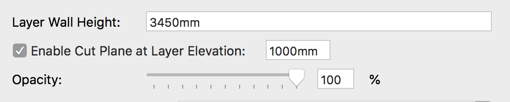
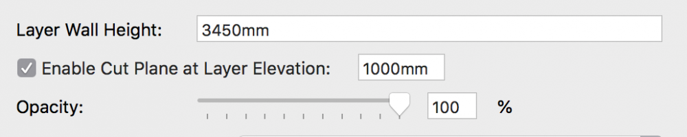
I have a plan with multiple design layers. I wish to set the section of the plan view 'cut' to a certain height - see attached screenshot of layer settings in organisation browser. I set the height I want that layer to cut at - nothing changes. How can I change the cut height of that layer? This is an architectural drawing, it can't be an open gl projection of a model in clip cube. Thanks
-
I deleted and replaced these items in an effort to 'refresh' them. After a 1 hour 45min ifc export that still hasn't fixed the problem. On top of that I've now discovered that other objects are now missing in the ifc where they weren't before in previous exports. This lack of reliability is entirely frustrating, and it makes it IMPOSSIBLE to meet any deadlines.
-
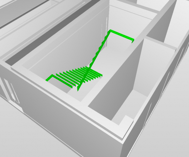
I’m carrying out a pre-issue check of the vwx to ifc file in Solibri and have come across the error shown below. Exported geometries on a number of objects (not restricted to stairs) are exporting incorrectly. This hasn't happened in any previous ifc exports of this file and I’m at a loss as to why it should start now. VWX's ridiculous ifc export times isn't helping matters. Has anyone experienced this? Thanks
-
My wish: VW2021 to have no new features. Please.
Martin d replied to line-weight's question in Wishlist - Feature and Content Requests
Folks It's 2018. Why is VW 2018 SP 3 just completely quitting when it encounters something it doesn't like. It doesn't even get an opportunity to save. This isn't a specific corrupted file issue. This instability is ridiculous, it makes it completely unreliable, especially if there is a looming deadline. Setting up a backup is not a sufficient solution, it breaks workflow and you spend the next 30mins trying to work out why it crashed in the first place. Most importantly destroys the user experience, please sort this out! macOS High Sierra iMac (Retina 5K, 27-inch, 2017) 3.4 GHz Interl Core i5 16GB 2400 MHz DDR4 Radeon Pro 570 4096 MB -
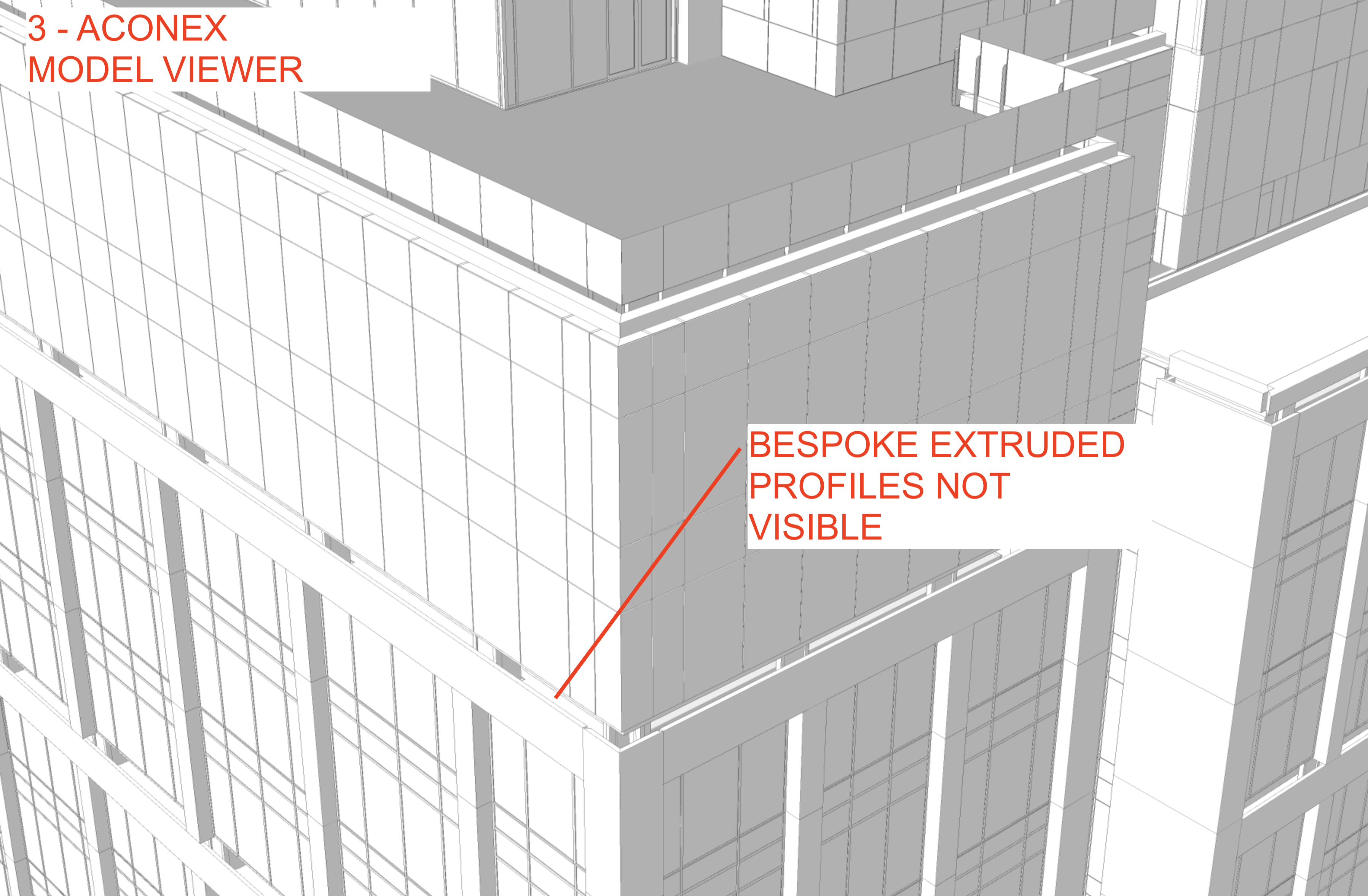
ACONEX - MODEL VIEWER - IFC EXTRUSIONS MISSING
Martin d replied to Martin d's question in Troubleshooting
***SOLVED*** Thought I had already done this, but apparently not - You have to make sure that both the path and profile have ifc data attached. Shows up fine now. -
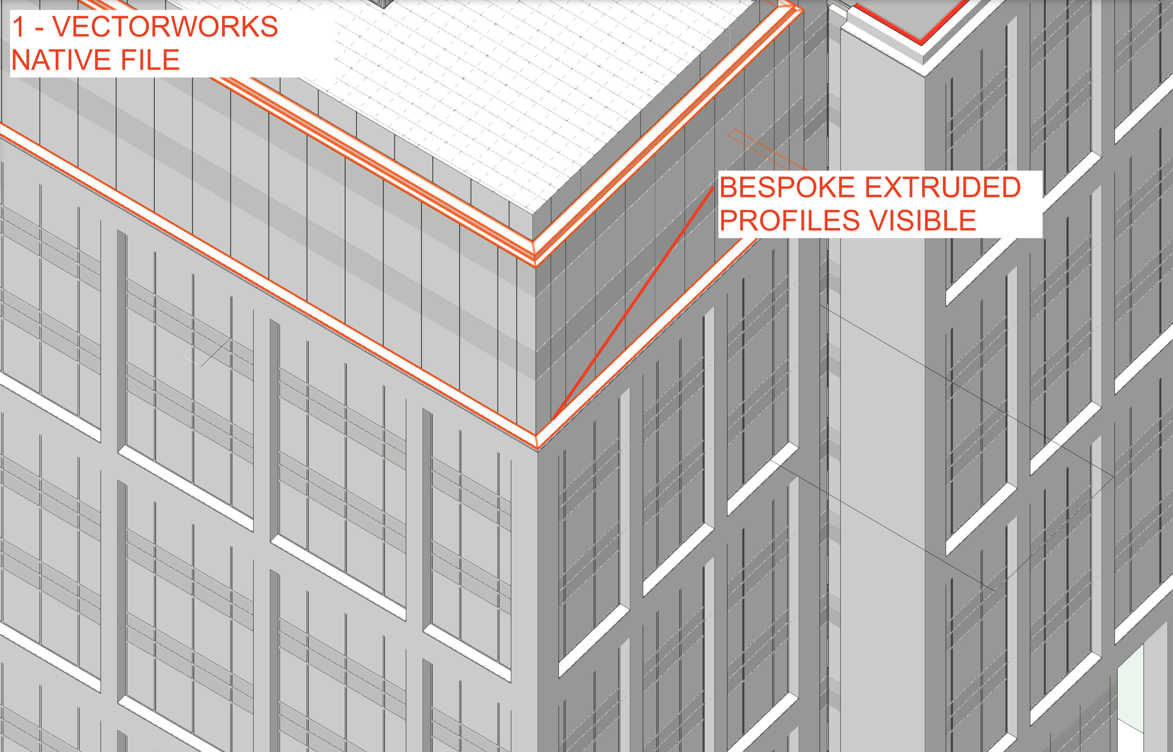
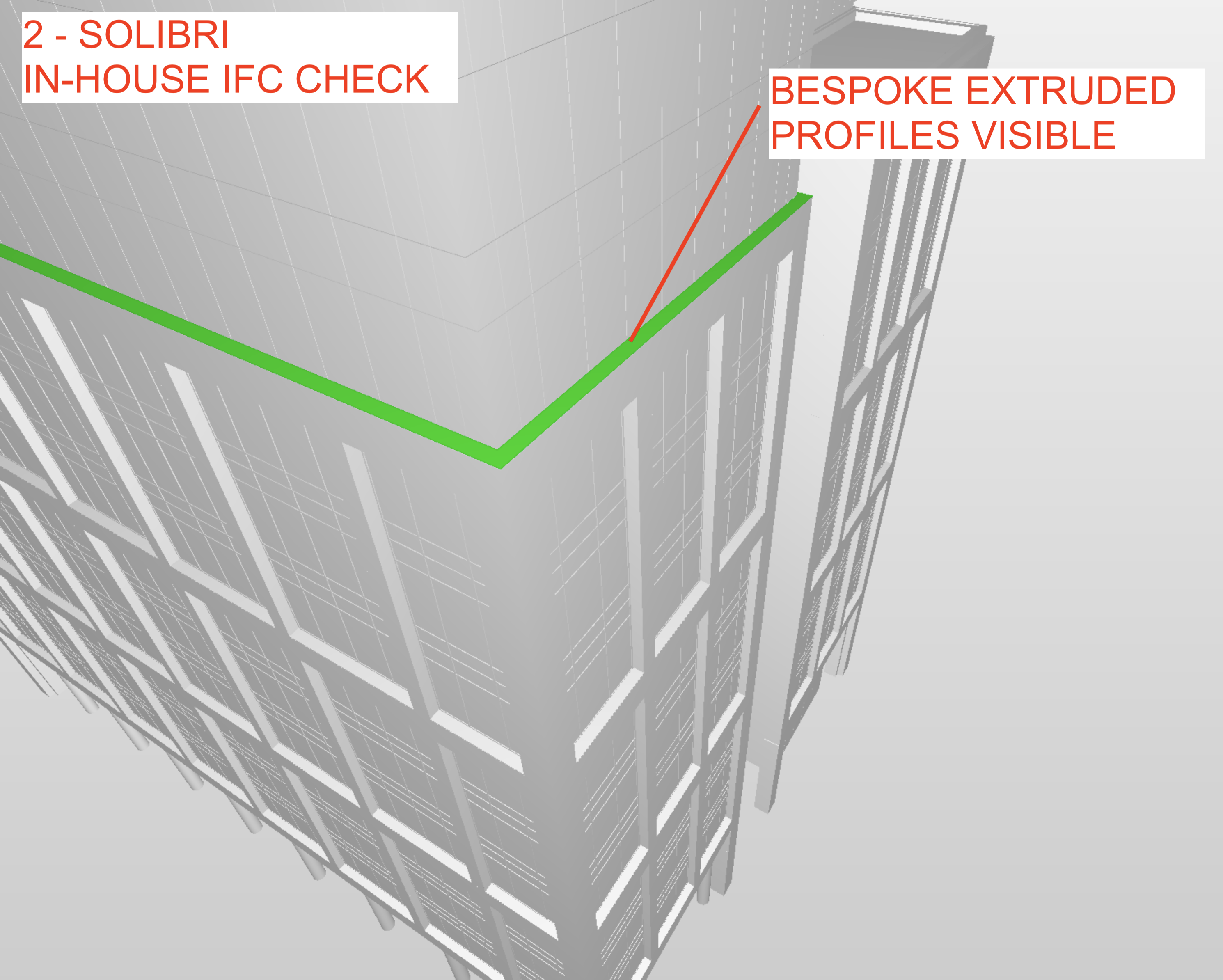
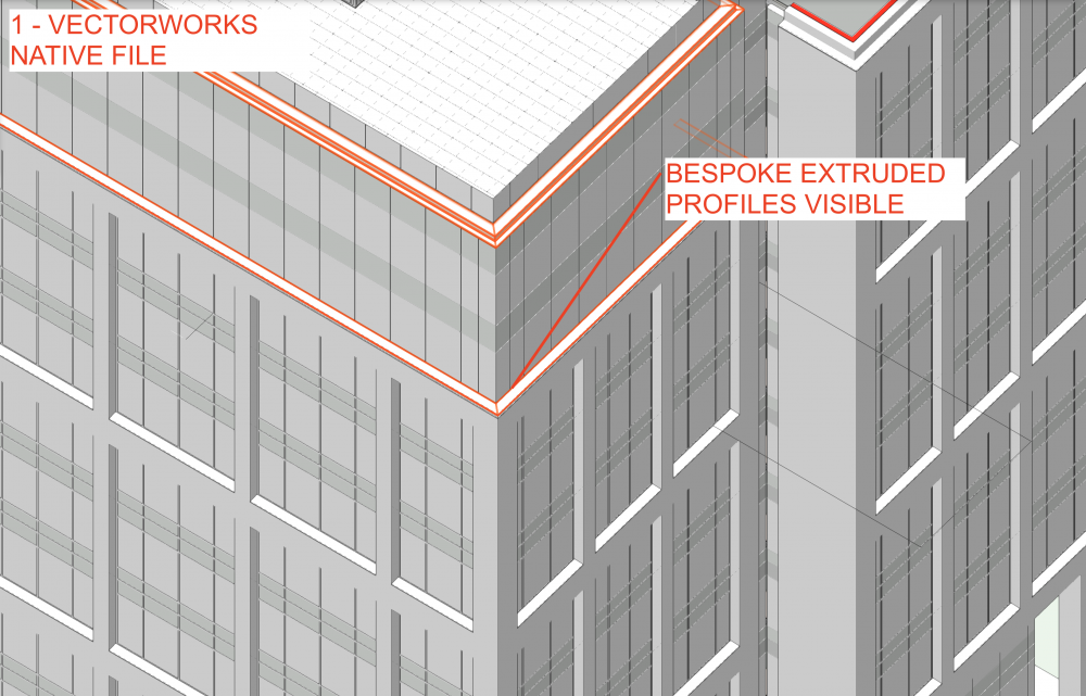
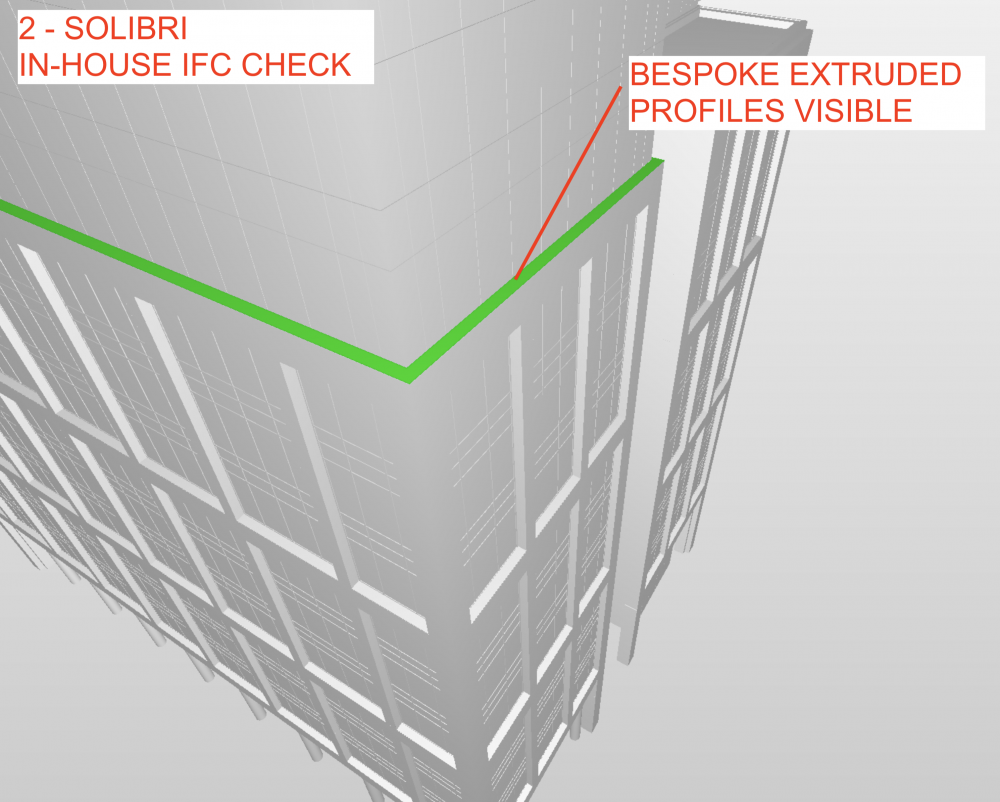
Hi all, We are using Aconex in a project and Im having a problem whereby the Aconex model viewer isn't showing any extrusions (flashing profiles etc) - see attached below. Ive made sure to attach ifc information to the extrusions, and checked the ifc in Solibri before uploading - which shows the extrusions, but when we upload to Aconex theyve disappeared. Im looking at the minute at converting the extrusion to a solid etc, but I can't see a quick solution. The ifc has been sent to Aconex help, but weve got nothing back - VSS believe its to do with the Aconex viewer. Anyone have any solutions??? thanks

-
Have you set your view to unified? Something similar happened to me and I think that was the issue.
-
This is a wish for an override for imported plane attributes to match the preferences of the main file: main file document preferences set up to 'screen plane only' - (or whichever) import the selected items from other file into main file vwx detects that 'objects being imported into current file have plane different to document preferences' question then is asked - 'would you like to change their plane to match current preferences?' - select yes or no, imported object planes are amended BOOM! - No more imported objects in different planes This would have to include groups, symbols, lines, poylines etc Don't see how this is any different from when you import textures or symbols that are the same - it always comes up with a warning symbol like the above. Thanks
-
cberg thanks for this, it worked perfectly. I'm wondering how to create a vworks wish/request - on a protocol that detects differences when importing from one file to another - goes something like this: main file document preferences set up to 'screen plane only' - (or whichever) import the selected items from other file into main file vwx detects that 'objects to being imported into current file have plane different to document preferences' question then is asked - 'would you like to change their plane to match current preferences?' - select yes or no, imported object planes are amended BOOM! - No more imported objects in different planes Don't see how this is any different from when you import textures or symbols that are the same - it always comes up with a warning symbol like the above. Thanks again guys
-
Hi there, I've seen a few topics around screen plane, layer plane and 2d drawings however I wanted to ask a different question. Is there a script anyone knows of that allows every line/polyline etc in the drawing to be selected and changed to screen plane? I know in the settings this can be set to screen plane only - the problem arises when something is pasted from a previous drawing this setting becomes overridden. If anyone knows how to quickly change this without having to go through each item and change to screen plane please let me know! Thanks.
-
***SOLVED*** Press 'G' at the point you wish to offset from, this will create a datum point. A smart coordinates tab appears beside the pointer, from there you can input the offset distances required. Works every time when using the 'add frame tool'
-
Hi there, I'm creating a curtain wall with a regular grid - 1500mm mullion spacing - which I've preset in the CW settings palette. At certain points however there are mullion spacings that aren't repeating - 750mm, 1000mm etc - so I'm using the add frame mode in a front facing ortho view. The problem I'm having is that I'd like to use a guideline (drawn in screen plane) to accurately place the new mullion but VW simply wont register the line of the new mullion when I click to start one, even when it's picked up the guideline's snaps. Is there an accurate way to do this? Or do I have to draw the mullion randomly, then move it to the place it has to be? If anyone has a scientific method of doing this I'd like to know it. Thanks.