


Michal Zarzecki
-
Posts
276 -
Joined
-
Last visited
Content Type
Profiles
Forums
Events
Articles
Marionette
Store
Posts posted by Michal Zarzecki
-
-
@Pat Stanford, I must be doing something wrong. Texture Mapping is still disabled and now every plane is smeared. How come in some files I don't have this problem at all?
Perhaps someone would help me with the workflow.
I have all components assigned to classes and textures set by class. Is that a good way to do it, to control the appearance from one location (class settings)?
-
@Pat Stanford, I am not aware where those settings live. Is that when I try to edit the texture? Sorry for being slow about this.
-
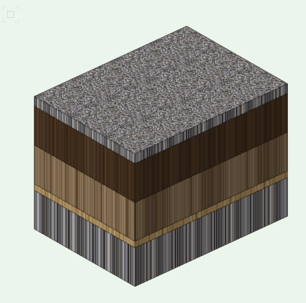
Hi all,
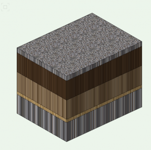
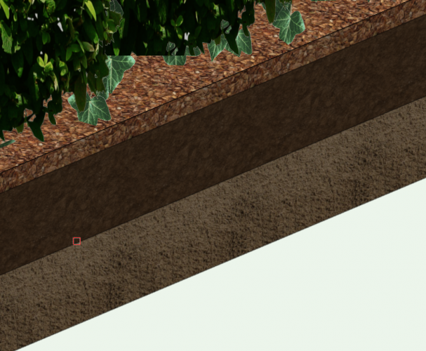
I recently, in a new project I created a number of Hardscape instances with textures. Unfortunately, I experience mixed results - with some textures being rendered/ displayed correctly whilst most looking smudged. See what I mean below. Can anyone point me to settings which control rendering of textures within Hardscapes?
-
Hello all,
I agree that the tool needs some more attention. I recall there have been a number of troubleshooting posts regarding various aspects of the tool, e.g. posts being rotatet at 45 degrees at corners, panels created in the middle without a possibility to set its alignment, no possibility to have straight and inclined sections in one object.
I have recently noticed another thing which is a bit limiting. I tried to create a weldmesh fence with rectangular aperture, where vertical frame bars are at different distance then the horizontal ones. The settings seem to allow for only one distance to be used which results in square aperture. Am I missing something?
I really struggle with designing railings on top of inclined walls. Even when drawing it traditionally (or more contemporary traditionally in CAD), one needs to consider offsets and elignment to achieve a pleasantly looking balustrade/ railings. Making straight sections and inclined separately and trying to get them work is either impossible, or very difficult, but certainly time consuming. Some level of improvement can be achieved with extruding along polyline. What disappointed me eventually, was the fact that the plane of end profile, if still on a pitch, was inclined which didn't work with the end post of my balustrade. All very time consuming and not offering value for [the commission] money.
I eventually tend to draw my railings in a section viewport.
-
 1
1
-
-
I agree with the above.
Some time ago, I posted a query about the location of settings which control which side the gate opens in a fence. The answer was that doors only work in walls :(. So basically the door/ gate I use within a fence/ railings object is a fake, just for illustrative purposes. I find it disappointing.
I also hope the developers will take our calls into account and rectify this omission.
@jeff prince, what you mention is absolutely right. At the moment, there is plenty of options in the door editor. Inserting custom design door/ gate leaf should not be an issue.
-
4
-
-
Thank you all for your input into this thread. I do understand the frustration, when tools (either software itself or commands within) rather than help, require more education to use it. At the end of the day we are in business (landscape or whatever) and we need computers to aid our work and make it efficient, not add to it.
I love the concept of 3D modelling and parametric design. Unfortunately, the learning curve is quite steep and, as @EricK mentioned, some tools require too much input and parametrisation before they can even be used. This is often the initial time investment and then the resource can be used elsewhere, but where projects vary significantly, repetition of the process is difficult to avoid. I think this may be fine for architects, who need to produce rich documentation, but in landscape industry, this seems often to be too much and not offer value for money. At least for the time being.
In the practice I work for, we decided to go VW so I tend to make the most of it and learn every day. It just get uncomfortable when my employer starts asking why simple things take me longer than before.
Now, regarding the stake tool and grades, I have been using these for the time being to report on the levels and coordinates. Designing levels with grades is quite ok, thanks to the fact that a network is being created. What I found missing for the time being is the ability to find a distance based on the start level and gradient. I need to calculate that first, which sort of kills the point of the tool. The second thing is the ability to update levels both ways, once the grade is inserted - in such cases, I need to redo the grade in the other direction.
I haven't seen stakes to return elevation of 3D objects. They seem to provide options for reading elevation either from exiting or proposed model. Hence I tend to use 3D loci first.
What we tend to do and need is annotation of elevation of objects such as walls, kerbs, fences etc. and a tool which can do that easily would be anticipated from a sophisticated software. I think stakes work ok in plan, but then the same information needs to be annotated in sections and elevations. For the latter I have been using the Benchmark Elevation Tool, but with mixed satisfaction. I particularly struggle with the layout of information within the tool when in left orientation. I need to find some tutorial on using this one.
What are your workflows guys? What would you recommend?
-
1
-
-
9 hours ago, Tamsin Slatter said:
you can put all your fields into one text box, then you won't have the problem of fields overwriting each other. You can also insert a text string among the fields without any problem. Here, my text strings are "No." and "Press Return Here", and the other data comes from fields.
Yes, I know all that and yet one still needs to create a particular data tag styles for different objects. My reflection was that this could be much more flexible, if the fields available in data tag could be inserted inside any text or callout object.
Another thing is that it seems that Data Tag object's width cannot be manipulated in the same way callout can. There are no vertices that allow the text box within the tag to be stretched.
I don't want to dwell too much on the pros and cons of data tags and their formatting, as that's not the thread's topic, but I am happy to discuss it in detail.
-
2
-
-
Thanks for your thoughts and suggestions about the data tags.
I am using these for annotation of symbols and plugin objects, but I have the fact that you need to create separate styles for each sort of annotation. What I like in AC is that one can insert fields within a text string - whether it's just a text box or multileader. I have been using that for keeping an eye on areas of playgrounds in my projects or counting plants. No styling required. Ok, apart from multileader style, but this is just annotation appearance, rather than the content.
Another thing about data tags is that the text inside is so inflexible. If you have your fields arranged in rows, then when your text is wrapped the lower fields won't adjust and be obscured by the text field above.
I really wish VW look into that seriously, because at this moment annotation is very clunky and inflexible.
-
1
-
-
Hi all,
I know it doesn't respond directly to the discussed solutions, but I have been using 3D loci to check the Z value. 3D loci can be then converted to stakes to show the levels in plan. In the OIP one can then change the display mode from elevation to Description/ Elevation and add ToW, for example.
Nevertheless, checking the wall levels could be made more simple.
-
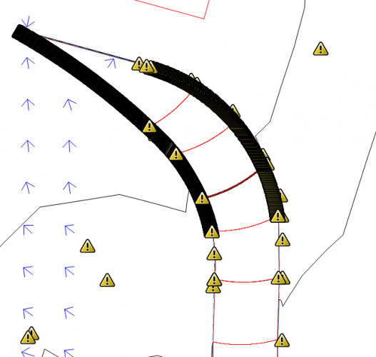
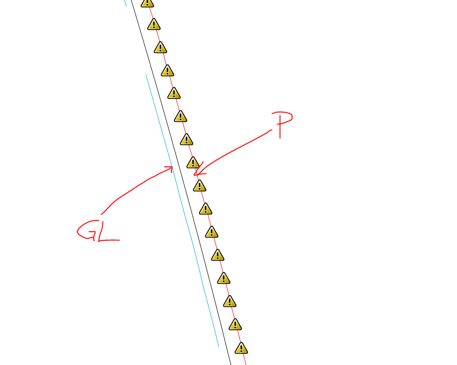
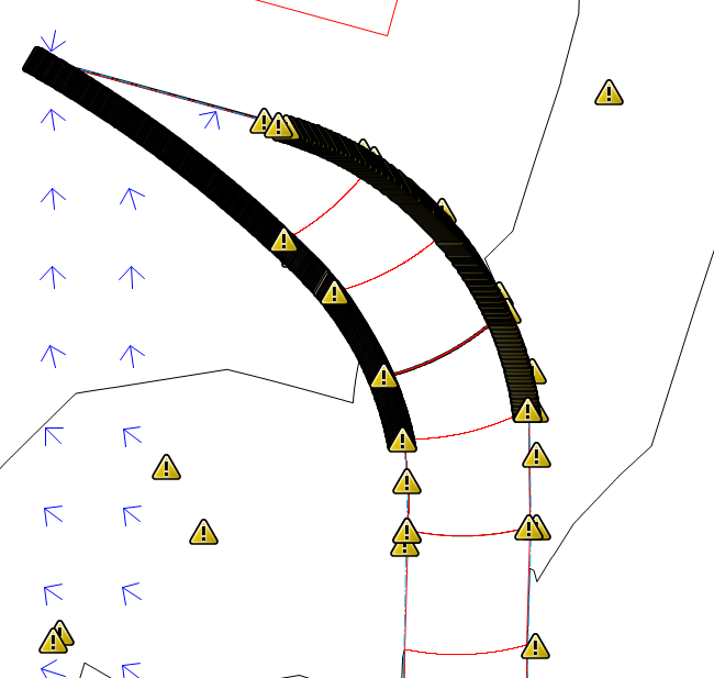
@J. Wallace, I share your pain.
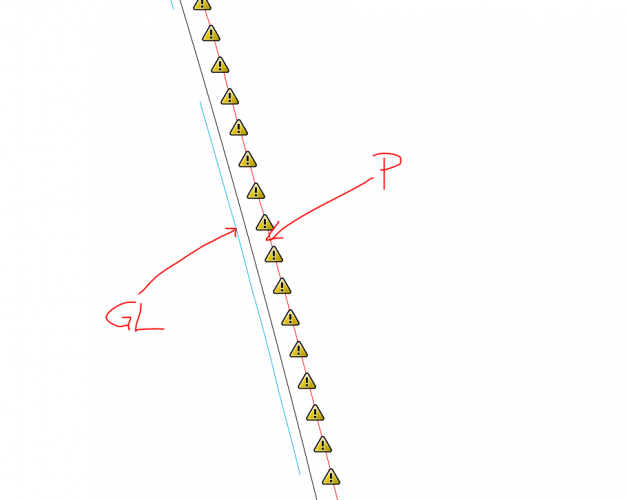
I have been experiencing issues with curvy Grade Limits and Pads. Even though they are centimeters away, I have over 1200 model conflicts saying that pad modifier intersects grade limit. See below. My Model basically even stopped calculating flow arrows because of these.
I am hoping there is a competent/ experienced user here who has an idea what causes the problem and how to resolve it.
-
Interesting, 12 years later I appear to have the same problem and can't find the answer.
-
Hardscapes in slab mode have slope options in VW 2019 and newer - not sure before. However, not as part of their style. I am yet to figure out how to use them, though.
-
@Hans-Olav, thanks for that. However, I was a bit unclear. I meant pad in slab mode. I am working with hardscape and wanted to make a simple slab with long and cross fall. I just don't understand how the slopes work.
-
Guys, could you refer me to any video, guide or post where using slopes for slabs is explained? I just don't get it. I would be grateful.
-
@bgoff, thanks for sharing your method. I was thinking about using Records as well. haven't explored that functionality yet though.
What do you then use as planting within those Landscape Areas - generic plant styles as placeholders?
-
Hi guys,
I was wondering how you create, specify, annotate and schedule grassed areas in Landmark?
I did this for the first time recently and I am not that happy with the workflow I came up with.
I created a species for each grass mix with category such as Lawn, Turf, Meadow etc.
I created a Data Tag that return the mix name and the area.
I needed to figure out how to pick it up by the schedule.
In defined the Criteria as Type = Landscape Area and various names (criterium Name). To schedule the total areas per each grassland type I set the column criteria to Record; Landscape Area; Area. I ticked the Sum Values box.
Is there an easier way to do it?
Do I need to actually create species for these areas? I thought that I could filter for Polygons or closed Polylines, but couldn't figure out how to categorise them or name them.
I would love to hear how you do it or how you think it would be easier to do it.
-
@Boh, thanks for your thoughts. I think it should work when we realise a mistake like that which would reflect an error in the Plant Style. However, in both these instances, the Plan Styles were either correct or rectified, but the schedule was not able to pick it up. My guess is that there is an issue with plants in Landscape Areas.
I once had a problem with plant style not being correctly expressed in specimen planting either. The Support Team was contacted but not able to explain the issue either. I needed to reassign the style to get it work. I suppose there must be some tiny bugs that randomly cause the styles to fail to work. It is then easy to fix it, but the malfunctioning specimens or LAs need to be identified first. This is the experience I have had with such issues so far.
-
2
-
-
@Pat Stanford, you may be right about what the LA is, but I don't think this is a problem. Most of the plants in my project are within a LA and they work fine.
As I said earlier in this thread, reassigning of the 'stubborn' plant definition within all LAs remove the incorrect behaviour. My first encounter with it was the reason I started this thread (apparently). Back then, the change that I made in the plant spec didn't go through to the schedule. Now, one plant wasn't picked up at all in the schedule, whilst another one had no Root Protection field value.
Regarding selecting Plug Ins in the criteria - the first time I did that I had double numbers of plants, because the schedule also picked up the ones in Data Tags.
-
I also struggle with 'symbolism' and 'stylism' in VW. I appreciate the use of styles, but in VW it has been quite inconsistently executed for different object. There is a number of posts where Members are unhappy about how styles are then applied to new features - or actually how counterintuitive it is to apply a style to already created object, such as Hardscape or Landscape Area.
A good example of styles that are easy to create and use is Illustrator.
A simple solution where Symbol colours can be modified by class or by symbol would be great.
On 3/26/2018 at 2:35 AM, BenV said:IMO, this might be the only functionality where ACAD wins out over Vectorworks.
I actually have found already quite a number of things that are much simpler and more flexible in AC, such as blocks (even making a dynamic block is very easy), multi leaders, panning within an active viewport etc.
-
Guys, I think I found out what had been happening.
I actually had a similar problem before, but in a different form. Something is wrong with Landscape Areas. Sometimes Plant Styles don't get expressed through them correctly. I don't know what precisely this is associated with.
I noticed that if something is going wrong with plants which are used within Landscape Areas, then they need to be reassigned in settings. That always rectified the misbehaviour. The problem is that this makes the planting plans and schedules quite unreliable. One needs to thoroughly check that everything works and being picked up in schedules. I am not sure if there is any kind of inspection tool. In one of the competitor packages I used to use, there was a tool like that. It checked if all planting areas had been labelled, and so on. You would be surprised how easy it is to miss some areas on large schemes.
-
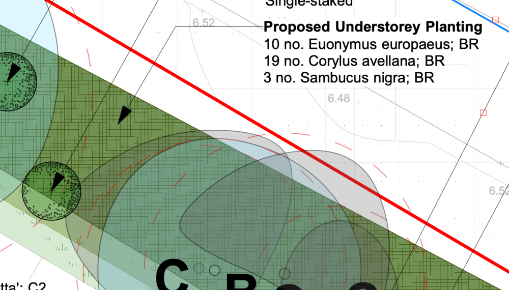
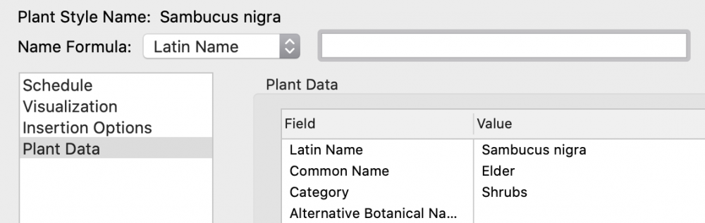
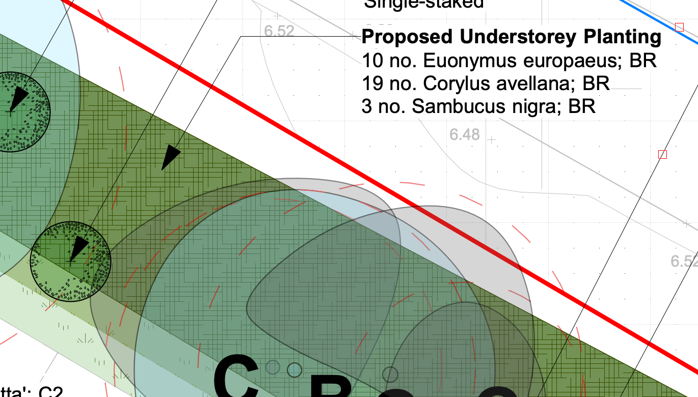
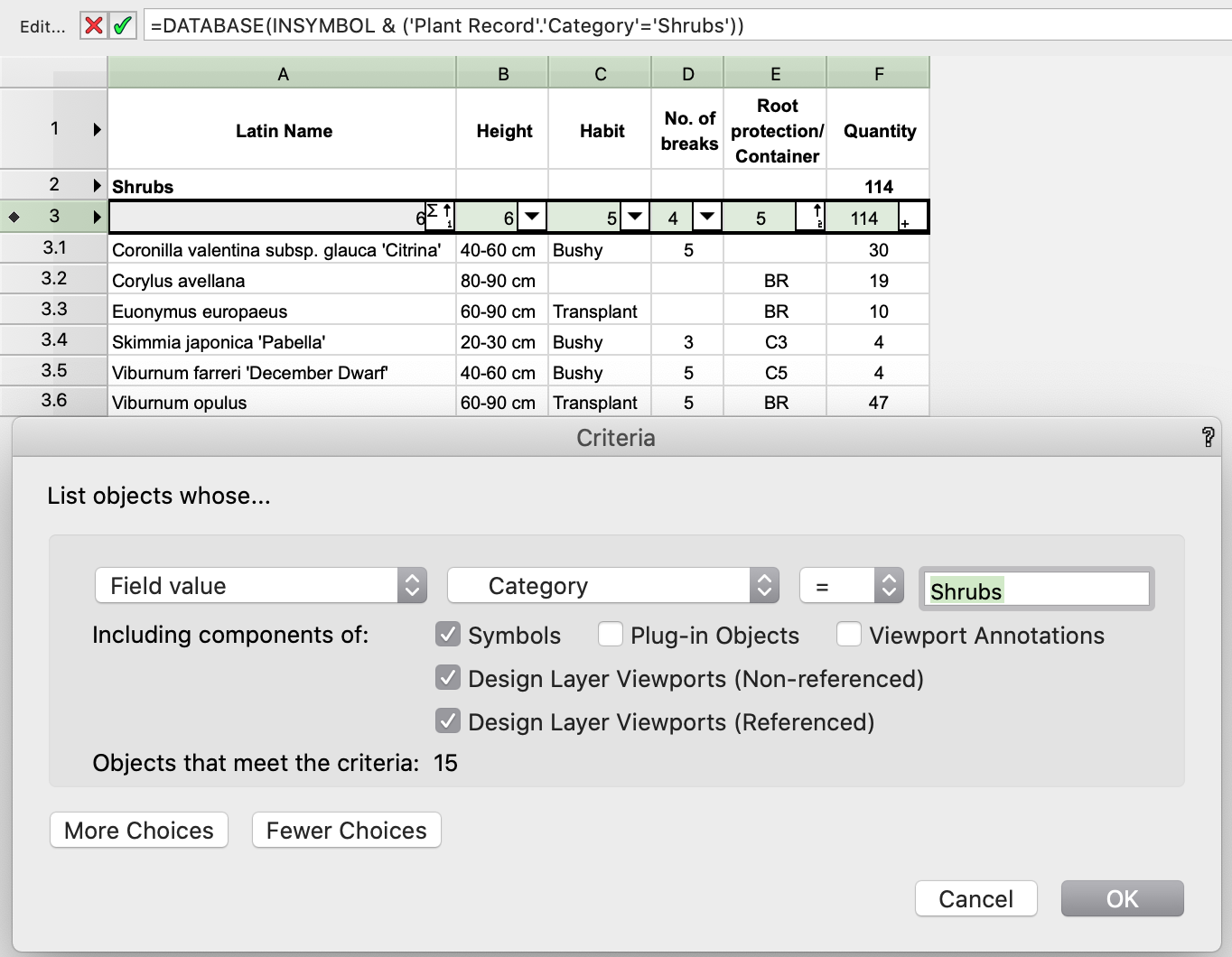
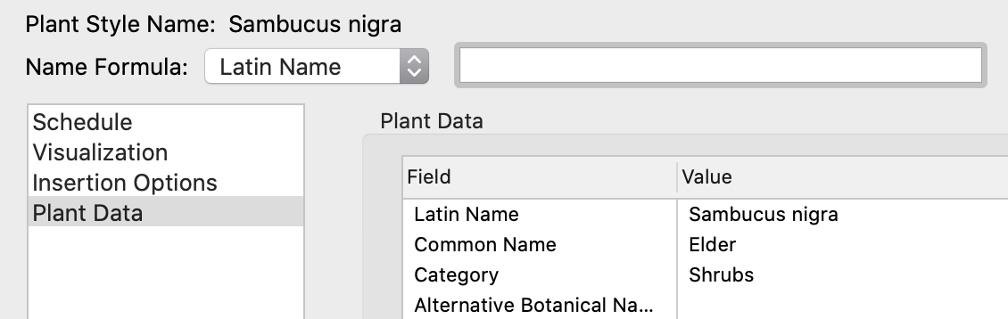
@Pat Stanford and @bgoff ,
Thanks for coming back to me on that.
See the attached images.
Sambucus is categorised as Shrubs. The criteria are set as to pick this up, but there is still something not working.
And yes, I do recalculate the worksheet.

-
@Pat Stanford, can I use your wisdom and experience with worksheets a bit more?
I made a Plant Schedule for another project but it seems it doesn't pick up some of the plants from the drawing. I checked the Criteria, Category fields in both the schedule and the plant style, but still nothing. The plant is present within the drawing/ plan so I would think everything is correct with it.
I also noticed that with other plant it doesn't pick up the Root Protection field value. Again it's not a global issue, but problem with individual parameters or plants.
Any idea what else to look at?
-
I actually found out what is happening so hopefully that will help others.
My reference is a dog drawing and it seems that the layer/ class greying out doesn't work with these. What I did then, I found out that I can control the properties (colours) of dwg layers from the Organization level. I went to Viewport and Visibilities and changed whatever needed to gray.
Don't hesitate to write to me if you find it helpful but need any help to execute.
Or, perhaps it's only been me not aware of that solution.
-
1
-
-
15 hours ago, Matt Panzer said:
What we do need, is a way to define and place a Gate into a Railing/Fence object. IMO, this should not have anything to do with Wall, Door, or Window objects.
For the time being, I just used the door symbol in thin air, i.e. not associated with any wall. I simply needed to insert a dynamic door symbol for which I could define the width.
Any more landscape designer-friendly approach than using Door tool would be much welcome.
I suppose a consultation exercise with landscape and garden designers would give some insight into the traditional design process and how VW can assist with that - rather than to hold back or require any walk arounds.
Kind regards.
-
1
-


Hardscape - Texture Problem
in Troubleshooting
Posted
@jeff prince, thank you too for trying to help.
I did read the advice in your post, which @rDesign referred to. @Pat Stanford recommended the same here
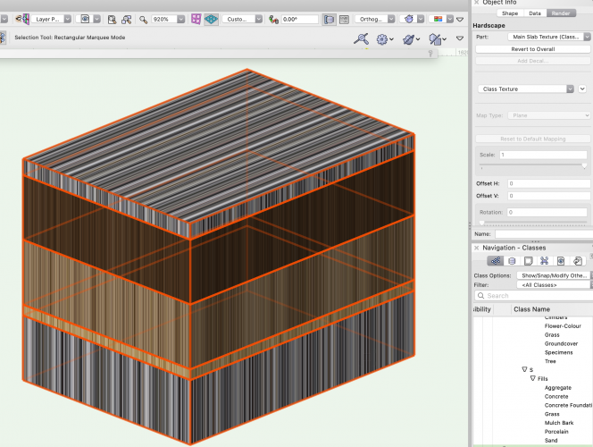
As shown in my screenshot here, I changed the Render settings to Main Slab Texture with Class Texture option and it didn't enable altering the Map Type option (you can see it is still greyed as Plane).
Do you mean you edit textures in the Slab Style that defines all components within a given Hardscape? To my experience and understanding of advice given elsewhere in the Forum, Hardscape do not have styles, like Plant Objects, so Changing the definition of a given Hardscape in the Resource Manager won't actually change anything in the instances already existing in the model. I wish the Hardscape settings could be retrieved from the RM whilst editing the instance. It says Active Settings - how is that helpful?
This is another level of complexity in VW, where Hardscape has its settings and when used in Slab mode, the slab has components which are controlled by yet another style. At least the Slab style can easily be replaced.
Equally to Hardscape, Planting Areas do not really have styles either and cannot be retrieved from the RM. I was advised to use eye dropper to copy settings between existing PA object in a model and a new one. I find this behaviour quite inconsistent in VW. Why Hardscapes and PA's cannot be defined by style and retrieved from the RM in a similar way Slabs are? When I discussed that before, I used Adobe Illustrator's Graphic Styles as an example. One can change the GS in Appearance tab and update the GS definition, which will make all objects that use this GS update its appearance. Nice, easy and intuitive.
Have you got similar reflections about this, or it's just so hard for me to get used to the VW logic?