


Mikedk64
-
Posts
105 -
Joined
-
Last visited
Content Type
Profiles
Forums
Events
Articles
Marionette
Store
Posts posted by Mikedk64
-
-
Hi,
Sometimes when I create a dimension in annotations on my viewport, I get these small grenn dots. So when the object is moved on my design layer, the dimension follow on the sheet layer.
But this is only sometimes. Why does this only happens sometimes, and what is the magic way to make this happen?
-
Thanks so much Markdd!
")
-
That worked, thanks
-
Hi, why do all of my lines in my viewport look blurred?
I have chosen openGL in background render, and it is just a box with a grey fill
-
Hi,
I have this single layer wall (100 mm). The wall has its color, fill etc. attributes from a class.
In this class, I have drawn my own tile, as I use as the fill. This works great when I do a section view in the wall and looking from the front.
So far so good.
But now I want to have a section view looking from the top, and in this section I dont want the same fill in the wall.
Is there a way to have 2 different fills for a wall, maybe controlled by two different classes or maybe something else.
-
Ok thanks guys.
I think i'm making details, and add them to the annotations.
@GadzooksThe file was just to get something to explain. My walls in my project is not builded like them in my test file, but thanks
-
Hi,
Maybe it is easier to explain it with a file
")
In the test file, have I created four walls, with a "normal" brick texture.
Then have I created a section view of the wall (See the sheet layer) On the left side is the real section view from the design layer.
On the right side is the view as i want to have. This view is created from the section view, but with a 2D annotation sketch in the viewport.
This will also work, but it would be cool to have it without to do the 2D sketch.
-
Thanks Markdd
But what if i want to see the bricks in my s4ection view of the wall?
It is in "Hidden line" render, so what I can see is, that i cant use yours suggestion?
-
Hi,
Is it possible to have a 3D brick texture on walls?
so the brick is sticking 2 cm out of the wall.
-
Ok, that was also my first thought.
-
Thank you Matt,
The option was hidded for me, but it is working now
-
That's seems to kind of work.
Thanks
-
That was also my first thought.
It do also work, but then when i create a slab of these walls, it is kind of not link to the three walls.When i move the blue or red wall, the slab follow, but when i move the green or all three, the slab converts to "manual" and break the link.
(See my file)
-
Hi,
Is it possible to give a wall different colors/textures on the same component?
I have a 10 meter long wall, that i like to give 3 different colors. the first 2 meter in red, 2 m eter in green and 6 m in blue.
Is this possible on the same wall?
-
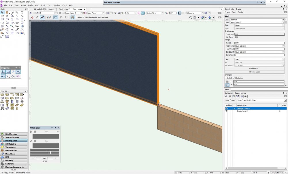
Hi,
I know about the components and classes, this is just a test file for you guys
I have tried with moving the design layers, but it doesn’t seems to work, if I understand it correct.
Here can you see that it is the same result, with the Layer 1 on top or underneath ( in the first pic, am I showing the "handle" I use to drag)

-
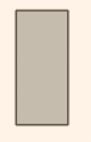
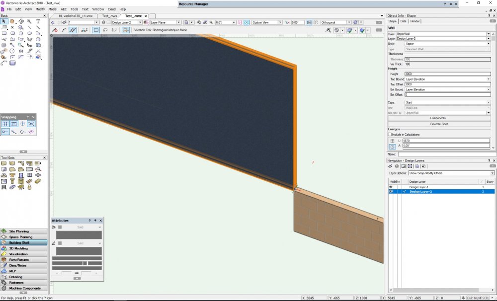
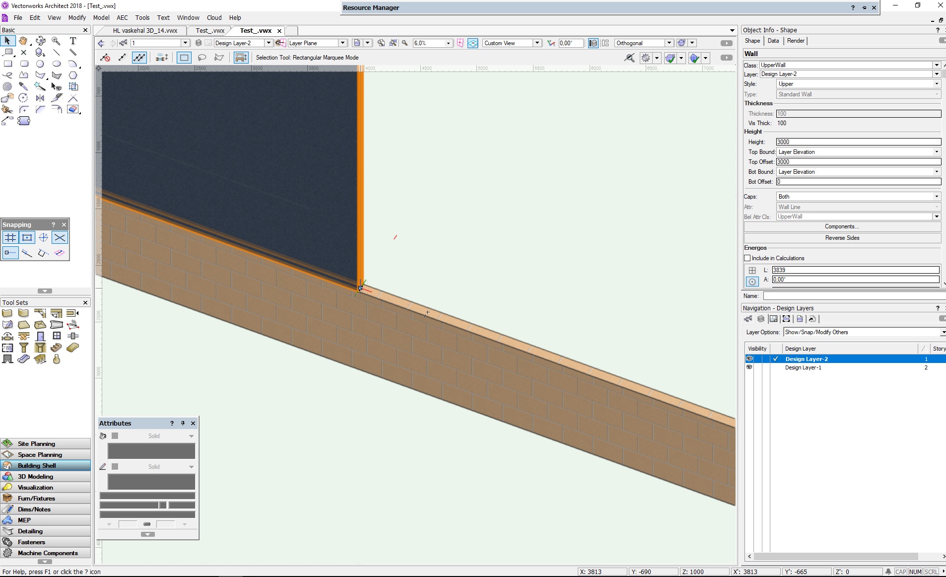
Hi,
I have a question regarding wall stacking. (I am new to vectorworks, so maybe is it stupid)
I have this two walls on top of eat other. The walls has two different wall styles and are on two different layers. The top layer has a elevation, that matches the height of the lower wall.
The question is, when i edit the value of the top wall length, it changes to the correct length. But if I drag in the wall to get it longer, it removes the lower wall?
So I can change the upper walls length by value, but not by dragging.
How can this be, and what can I do to avoid this?
See my attached test file
-
Hi, "This is a repost from ealier. I didnt get any answers, so i thought to try again"
I have this floor made of following layers, Sand, concrete and tiles.
The two first layers is just flat and wall to wall. But the tile layer has to have a virtical edge. In my test file, did I use the slab tool with the three layers, and afterwards did I make a 3D object, added
that to the slab and so on.
My problem is, that the top layer (tile layer) dosent follow the wall anymore. So is there a way to make the little edge, and still keep the auto-bound to the the wall?
I do also need to have a drain in the floor (like in the file)
I have attached a file, with my example.
-
Hi,
I have this floor made of following layers, Sand, concrete and tiles.
The two first layers is just flat and wall to wall. But the tile layer has to have a virtical edge. In my test file, did I use the slab tool with the three layers, and afterwards did I make a 3D object, added
that to the slab and so on.
My problem is, that the top layer (tile layer) dosent follow the wall anymore. So is there a way to make the little edge, and still keep the auto-bound to the the wall?
I do also need to have a drain in the floor (like in the file)
I have attached a file, with my example.
-
This is not exactly what i am seeking.
I would like to have a pop-up box (Or similar) when i starting a new dokument where I can type in Name, adresse, company ect. And these information, will be used to fill out all tittle blocks in this document. So if i change the name on the parameter, the name will change on all the sheet layers.
I can not put the tittle block on the design layer, because I use multiple layers in my sheets, and some are used in more than one sheet layer
-
Hi,
I am new to Vectorworks and before this i did work with inventor, Creo and so.
In these program, was it possible to create a default title block, that got its informations from the part, such as name, number, scale. It was also possible to do, so when the title block was updated it automatic updated the date.
I have tried to follow a lot of tutorials and guides, and I did succeed with creating a title block, but I have to type in everything, on every sheet.
So my question is:
1: Is it possible to create a title block that goes on a sheet layer, that gets its information from the viewport from the design layer? So when I do some work on a design layer and make a viewport for a sheet layer, the informations from the design layer follow to the title block on the sheet layer.
2: Is it possible to do that, when i create a new sheet layer, will my title block automatic inserted in the ned layer?
-
Hmm okay
So you did succeed with walls?
So if you only draw a wall in you design layer and making a viewport of this, you can constrain a line to this wall on you sheet layer?
-
Maybe it is me, that dosent explain well, sorry
If i draw 2 squares in my sheet layer can i easily constrain them.
The problem is when i draw a square on my sheet layer, and trying to constrain it to my viewport from my design layer
-
Hi,
i am new to VW, and i need some help

I have this 3D model, and I need to add some details to it on the drawing.
So i made a viewport from the top, and jumped in to annotations in the viewport. Then did I make a line, and tried to use a "constrain coincident" on the line to the "side" of the model.
Then i get a "This constraint is not valid" error.
can it really be true, that you cant add a Parametric constraint on my 2D drawing?
-
Hi,
I have two different walls on top of each other. Is it possible to do so, when i move one of them, the other follow.


Floor hatch align
in General Discussion
Posted
Hi,
I have this slab with tiles, and a drainage in the middle.
For my drawing i want to show the tiles in "hidden line" and there I attached a hatch for the texture on the slab.
Theres is only one problem. The hatch is not aligned all around the drainage. So every side is offset,a nd it look terrible.
Is there a way to get a clean hatch surface, so it looks better?