


jcogdell
-
Posts
954 -
Joined
-
Last visited
Content Type
Profiles
Forums
Events
Articles
Marionette
Store
Everything posted by jcogdell
-
@kdenham I just had a look at the JBL speaker symbols that you are using in the array and the problem looks to be that the data record dimensions do not match the geometry inside the symbol definition. Since I'm not really familiar with JBL speakers I'm not sure which is incorrect, the data record or the geometry. I'll put a bug report in for it
-
Distance between two symbols within the data manager?
jcogdell replied to AStein's topic in Entertainment
@AStein Fully understand that it can be hard to work with a last minute plan changes or a design prepared by a third party, especially if you are dealing with another contractor not willing to actually do their job properly. But does this leave you open to being legally liable if something goes wrong due to the information you have provided? To me taking the extra time is worth it from a safety point of view and just as importantly, minimising potential liabilty if something goes wrong on site. -
Truss system not Properly balanced error not in documentation
jcogdell replied to sbarnett's topic in Braceworks
Here's the link to the error message in the Vectorworks help https://app-help.vectorworks.net/2024/eng/VW2024_Guide/Braceworks/Displaying_and_correcting_errors.htm If you DM me the file I can check what is causing the issue. -
Distance between two symbols within the data manager?
jcogdell replied to AStein's topic in Entertainment
@AStein Is this the sort of thing you are looking for? If this is what you need it can be created by adding bridles tot he hoists and calculating them with Braceworks. Braceworks will automatically create hanging points that will document the force acting on the beam at the connection point. You can then use spotlight numbering to give the hanging points ID's based on the beam they are linked with to make reporting on them eaiser.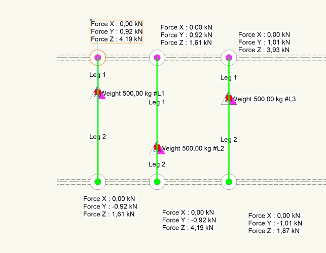
-
Yes this is standard behaviour across all of the Vectorworks objects like lighting devices trusses and hoists, that are not simple symbols.
-
The issue is that you are attaching the record to the hoist symbol, which is then buried inside the hoist object when the insertion tool inserts a hoist. This effetcively blocks access to the record attached to the symbol. The way to deal with this is to add the record to all your inserted hoists after creation, then it will be attached the the top level object and not tot he symbol inside the object.
-
My preferred way is to create a double clamp symbol, with the clamps offset to each side of the insertion point.
-
@Zach S Have you used a renderworks camera to create the viewport? A range of new cmaera effects and controlls have been added in 2024 and this may be causing the blurriness.
-
@aheininen Thanks for bringing this to my attention I'll get the bug report in to get it fixed
-
In the report criteria have you toggled on the subparts option?
-
Nivtec stage platform modules, leg configuration.
jcogdell replied to dtuck84's topic in Entertainment
The easiest way is to create symbols for each standard deck and attach a custom data record to them. You could use the generic stage deck symbols in the Spotlight library as a starting point For the legs you can either include them in the deck symbols or create a single leg symbol and then use it to create a set of group symbols with that are set up for specific leg configurations. The group can then be inserted from the resource manager and ungropuped to make it easier to report on how many legs you need -
Hofbolt 2 truss type not acting how i think it should...
jcogdell replied to Francois Catteau's topic in Entertainment
Hi Francois The straight runs will calculate, you will get unsupported errors for any sections connected to the mid span connection points. Rvrn if the truss doesn't have a Braceworks crosssection provided by the manaufacturer Braceworks will calculate it but the truss will be modeled as a default rigid object that won't react to the loads/forces acting on it. This means that it will transmit loads through to hoists and bridles etc but won't react to the forces itself, which means it won't calculate how that type of truss will deflect. -
There is a complete learning path on the Vectorworks University about the cable tools suite which explains how to use the tools and setting up objects for them. https://university.vectorworks.net/local/programview/index.php?id=25 To connect both power and data cables to a light you need to set up the electrical components for the power, DMX in and DMX out. If you only plan to do power cables then you can ignore the components. You can also set up your own cable part library and sets to control what cabels are available to the cable tool,. Lastly to force the cable tool to use the shorter cables look at the cable preferences and check what is set for the spare length and whether it is set to use the fewest parts or closest fit. The learning path has videos for each part of the workflow that go into detail how to work with the tools and features of the suite. Here's a trsample project from the university for cable planning https://university.vectorworks.net/mod/page/view.php?id=5711
-
@chaseurban From what you are describing It sounds like your resource manager cache has been corrupted, you don't need to reinstall to fix just delete the cache and then run the update library command The cache is in Users>******>AppData>Roaming>Nemetschek>RMCache
-
Hi Stefan Can you send me the file? so i can take a look
-
Truss defaulting to 3D symbol in plan view in Spotlight
jcogdell replied to symo's question in Troubleshooting
@symo as far as I can tell its working correctly in 2024 -
"Vectorworks 2023" is damaged and can't be opened.
jcogdell replied to Mauro Pujia's question in Troubleshooting
You can repair your install using the advanced options in the updater. Its located in the vectorworks **** updater folder in your application folder -
Truss defaulting to 3D symbol in plan view in Spotlight
jcogdell replied to symo's question in Troubleshooting
I've just been testing this and can verify there is definetly something wrong. It's only happening when you insert the second section of truss in a 3D view, so if you draw everything in 2D top/plan then it will work correctly. I'll get a bug report opened -
What version of Vectorworks are you using? What Mac os version are you running? and are the system specs in your forum signature up to date?
-
We have Applied in the library but you will need to access it through the premium libraries as you are using an older version of Spotlight. As long as you are on either service select or subscription you can either go to the customer portal and download the library or find it in the premium library section of the resource manager (make sire to have the premium libraries toggled on).
-
I don't think we have a C19 power connector currently in the default connector xml. We have the C13/14 (IEC6320) You can add it to the xml yourself and it will then be available once Spotlight has been restated. The easiest way woould be to duplicate the exisiting C13 entry, then update its universal and localised names. Here's a link to the cable connectors skill video on the university which goes through the process of editing the xml https://university.vectorworks.net/mod/overview/view.php?id=3065 Make sure to create a back up of your edited xml so that if it gets reset to default you don't need to edit it again
-
The P1 should be X: coordinate 356 (if you are using mm). In custom corner mode the diagram is not the eaiest to read and could definetly do with some love. The easiest way to check this sort of measurement is to look at how the default library content is set up for this corner type. The key rule to understand these measurement is that all straight truss symbols are drawn as though they are laid flat on the ground, running left to right from the intenal origin of the symbol. All truss connections have to align with the trusses center line, which defined by the above standard runs along the bottom centre of the truss geometry. This in turn defines how the P1 through P6 coordinates are calculated. P1 is the point where the center lines of the truss corners connection point meet
-
Once you have drawn the straight truss you will need to give a roll angle of -90° to correctly orientate it before adding hoists or lights. While looking at this I've noticed after roling the truss that in top/plan the 2D geometry doesn't display correctly and the autocconnect highlight is offset from the 2D geometry, despite being correct oin 3D views. I'll add a bug report. You may get better results by using the truss tool with a standard 2 chord truss, just use a model of truss that has similar dimensions to what is hung in your venue.
-
Spanner truss not acting how i think it should...
jcogdell replied to Jayme McColgan's topic in Braceworks
I had a look at your file If you calculate the truss line without the spanner truss or fake hoist supporting it, the 2 hoists have around 1000lbs motor load each (975lbs M18 and 1088lbs M19). With the spanner truss M18 has 819lb and M19 941lbs, so the spanner truss is taking part of the load but because this 'pick up' is not connected directly to the ceiling it spreads the load differently than if a single hoist hung directly from ceiling is used, since its going to multiple points, has to account for the spanner truss's own load and any other loads acting on it that would affect the calculation. -
Equipment Summary Tool bugged? Spotlight 2024
jcogdell replied to LiteDoctor's question in Troubleshooting
If this is happening on sheet layers then its a known bug that is currently being worked on. There is a work around, insert the sumaary key on a design layer and then use a viewport to add it to your sheet layer.

