jcogdell
-
Posts
955 -
Joined
-
Last visited
Content Type
Profiles
Forums
Events
Articles
Marionette
Store
Everything posted by jcogdell
-
Yes this is fixed, I just checked it to make sure (2021sp4) and as far as I can tell it is behaving correctly
-
In this generation of the cable tools Distributor objects are primarily designed to document/display how the system is connected, so there is no way to document the individual MCB's (breaker) and RCD's (differential breaker). The work flow for creating a distributor object is create or select a symbol for the distributor object in the resource manager right click on the desired symbol and use the attach record command to attach the 'CableDistributorRecord' by ticking it in the attach column while still in the attach record dialogue select it (highlights in blue) and hit the edit values button to open the record and fill in the data. For the Input type and output type fields you will need to use the connector universal name from the Cable Connectors xml file (found in your application folder>Libraries>Defaults>Cable Tools) exit the dialogue and save the new distributor into your user or work-group folder.
- 1 reply
-
- 1
-

-
Hi Ben There are 2 related problems that you are dealing with here When using Daisy chain mode you have to make sure to set up the auto-numbering to use the same cable run ID for each cable in the chain, or only the first cable in the chain will be given a cable run ID as it is the only cable directly connected to the breakout. If the cable doesn't have a cable run ID there is no data to push to the lighting device At the moment the lighting device circuit name and circuit number fields only get data pushed into them if the cable object is connected directly to a breakout. I will put in an enhancement request to have this behavior improved, ideally the lighting device should document the connected cable no matter what it is connected to at the other end. At this point in time the only option in Spotlight is to create a custom report documenting the lights circuit name, number and wattage.
-
From looking at the ACT notes about the plugin it was fixed fin Vectorworks 2019.
-
Hi Gabriel It is no longer necessary to use the import option to access speakers in the default Spotlight libraries. Instead select the symbol option in the source drop-down menu and then use the select symbol dialogue below to search for the speaker type you want to use
-
Vision Display/Projektion Horizontal dupliziert
jcogdell replied to Nehemia Bertschi's question in Troubleshooting
Hi Nehemia Wie haben Sie die Projektionsfläche in Spotlight erstellt? Haben Sie das 'Video screen Tool' verwendet oder haben sie selbst erstelt? Freundliche Gruße Jesse P.S Bitte posten Sie in diesem Forum nur auf Englisch, da die Mehrheit der Vectorworks-Mitarbeiter kein Deutsch spricht. Wenn Sie Unterstützung in Deutsch benötigen, wenden Sie sich bitte direkt an Computerworks. -
The basic problem is that there isn't any Braceworks cross section data available for any Tyler trusses, as they are not willing to share the needed structural analysis data for their products with us. This in turn causes auto-connect to restrict how corners will connect with trusses in 3D (it will only allow the corner to connect in the horizontal plane). Currently this is a hard coded restriction when there isn't any cross section data available, we are changing this as part of the 'Refactoring of Truss Engine' task that's part of the development roadmap but that doesn't really help at this moment. I've contacted a college on the content team to see if he can find a solution for you. If you have access to the structural data for this type of Tyler truss you could create your own custom Cross section for it, which in theory would fix the problem.
-
What type of truss and hinge are you using? From your description of only being able to bend the hinge or connect the custom corner in the horizontal plane (X/Y axis) it sounds like the truss you are using has no Braceworks cross section profile and is using the default rigid setting. Which then restricts corners and hinges to connecting in the horizontal plane Another possible issue is that bookend style hinges are restricted to only being usable in the horizontal plane (outside of a couple of exceptions this is per manufacturers recommended use guidelines, from my understanding). Effectively this mean that for this configuration you would need to use a center point type hinge.
-
Hoist Tool 2021 & Up Proper Weight Field & Format
jcogdell replied to MattG's topic in Entertainment
@MattG The default definition of the hoist fields are Hook Weight equivalent displays the total load acting on whatever the hoist is hung from, including the hoists own body weight and the total weight of its attached chain (max chain length x weight per meter or foot). Hoist Weight equivalent displays the the load acting on the Hoist Hook Force and Hoist Force display the same data but as a force (Kilonewton, pound-force, etc...) rather than a unit of weight. Since you are not using Braceworks you don't have to use these fields the same way. The only limitation is that the fields are formatted in the hoist properties according to the type of data they are designed to display, so fields documenting a force will use kN or lbf and weight fields kilograms or lbs (or whatever your document units are) This will not cause any problems, you could for example do a test hang of your rigging system, using load cells to get the exact loads for every hoist in the system and then add this to the hoist properties. The only thing to be aware of is that if your file is then run through Braceworks the values in the fields will be replaced by the results of the Braceworks calculation. The new hoist object record has 2 versions of each weight related field in its object record, plain and formatted. The plain version displays the weight in the internal format that Vectorworks uses (Grams) and the formatted version will display the weight using your document unit settings. The fields use the same naming as the Hoist properties. @stevenmorgan94 The enhancement request is in for this As long as you are not going to be using Braceworks you can do this, see my above answer -
You can set the measurement label (and the ID) classing in the hoist tool preferences before insertion using the classes button or after insertion in the hoist object properties the same way
-
How to change page size of Braceworks Calc report?
jcogdell replied to LenLindhout's topic in Braceworks
Not sure if this helps but you should be able to change the exported report's page size when printing from adobe reader in the print dialogue. I'm not sure how well it will scale when adjusting the page size if it is a big change (A4 to A3 for example) but from the preview it looks like it will work OK for going from letter size to A4 -
@Julia79 In the 2019 version of Spotlight this is a premium library, if you are not a service select member it will not be available. If you have service select then it will be in the Premium libraries section of the resource manager.
-
Hi Vitalio The content team should be reaching out to you about the truss library and time frames. You don't need Braceworks to create truss symbols, but it does make the workflow a bit easier as you then have access to the convert to truss command in the Braceworks menu and you can check the Braceworks behavior of the truss after creation. The workflow/best practice for creating truss symbols without Braceworks is create the 3D geometry for the truss geometry should be as simple as possible, as the more complex the geometry the bigger the performanence impact. The main point is to consider the level of detail that is needed, so things like rivet heads and dial and writing engraved into the truss should be removed, and truss chords and diagonals should not be hollow for example All geometry should be converted into a single generic solid, Meshes and NURBS can have a huge performance impact. put 3D loci at the each end of the truss as insertion guides, need to be positioned at the bottom center of each end (the left hand one will line up with the symbols internal origin once converted) and assign them to the Rigging-Truss-Insert Points class The main 3D geometry should be assigned to the Rigging-Truss-Truss class A second 3D bounding box geometry section should also be created for the simplified view, this should be assigned to the class Rigging-Truss-Simplified Create the 2D part of the truss symbol, correctly lined up with the 3D geometry, with he same classing (Rigging-Truss-Truss) this should include a text label with the short name of the truss and its length and assigned to the class Rigging-Truss-Label a 2D loci should be added at the middle point of each end of the 2D geometry and assigned to the Rigging-Truss-Insert Points class select the 2D and 3D geometry and run the Create Symbol command from the modify menu. In the create symbol dialogue make sure to correctly define the insertion point, using the 'Next Mouse Click' option in the insertion point section. The truss should be orientated as if it is lying flat on the ground with the center of the left hand end (at ground level) being the insertion point Once the the symbol has been created in the resource manager right click on it and use the attach record command to attach the truss record and the edit values button to fill it in. Activate the insert truss tool and insert the truss symbol, the first time you try to use the symbol the Truss Properties Dialogue will open and you can then configure the truss. Object Data The type field is important as it combined with the Connectable with field define what truss symbols can connect with each other. So every truss of a particular type (HD-44, H30V, etc...) must have the same type identifier Name is the full name of the truss Length is the length of the truss from left to right when lying flat on the ground and defines how our auto connect function works with the symbol total weight and distributed weight the Cross Section data defines how the truss behaves for Braceworks calculations. You can assign the structural behavior data to the symbol using the change cross section button, either rigid if you have no data, select from the existing list or if you have the data you can create your own by choosing the custom cross section option and filling in the fields. Important note: If you create or enter your own cross section profile it is your responsibility to make sure the data is correct and put in the correct fields. height and width are based on the physical dimensions of a vertical cross section of the truss Connectable with controls what types of trusses the symbol can connect to with auto connect, for example Eurotruss FD34 and HD34 can be connected with each other but are different types the Connection section controls whether the truss symbol uses a male and female end or neutral. in most cases we leave this as neutral by default unless the truss has forked ends Once the properties have been filled in the Truss Properties dialogue they will be saved into the symbol for future use If you have any questions PM me
-
I'll get it added to the cable connector xml file Since it will will likely not happen until service pack 5, you can edit the cable connector xml yourself to add it. Go to your application folder> Libraries>Defaults>>Cabletools and open the CableConnectors.xml with a simple text editor or xml editor, if you are on Windows Notepad works pretty well. Below is the entry for the VEAM P-14, copy and paste it into the xml. <Entry UniversalName="VEAM P-14" LocalizedName="P-14"> The position you paste it into the xml controls where it appears in the cable connector dropdowns through out the cable tools suite, the universal name is used internally by the tools and the localized name is the name that will be displayed in the cable connector dropdowns.
-
Another method is to set a working plane at the orientation you want the base of the light to insert. It can be a bit fiddly to get the hang of adjusting the angle of the working plane, but it will enable you to insert multiple lights without needing to adjust the Y rotation after insertion personally my preferred workflow is to snap the plane to the top of one of the truss chords in an isometric view and then adjust the orientation (click on the plane itself for the rotation handles) using the appropriate red handle while holding the shift key to make it easier to the plane correctly orientated
-
Your best option is to save your customised truss symbols into a user or workgroup library folder. They will then be available for future projects through the resource manager This will prevent them from being overwritten when ever a new service pack update is released.
-
It should be possible to connect it in all 4 possible orientations, sometimes you need to change your point of view slightly (using the flyover tool or one of the view short cuts) to get the other possible directions. We are currently working to upgrade how auto connect works to address this issue, it is on our Development road map as 'Refactoring of Truss Engine'.
-
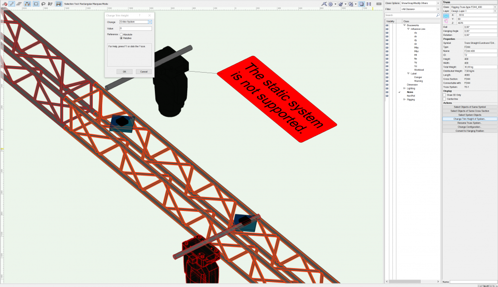
The most likely cause for this from your image is that the pipe has lost its connection to the truss and truss cross (blue diamond). If the problem is not visible in a 3D view, the easiest way to check if this has happened is to hit the 'Change trim height of system' button in the Truss properties and once in the Change Trim Height dialogue set the 'Change' drop-down menu to either stacked or entire system. This will highlight everything that is connected to the truss system, not just the objects directly associated with the truss line itself (which is displayed by the select system objects button). If this is not the case PM me the file and I will see if I can figure out what is going on
-
@Oliviaewing656 You will need to contact the UK Vectorworks office directly for this, Phone: 01635 580318
-
Use the distributed weight field in the Curved truss object properties,
-
I had a quick look on their website and couldn't find any CAD files that could be converted, so the only thing I can suggest is to use the Curved Truss Tool in the rigging toolset to create the truss.
-
Hi Jon The ColorSource Spot Jr is in the premium libraries. As long as you are a service select customer you should have access.
-
What our content team have done is create a template file with 4 circles to represent the truss chords, linked using the dimension tool to make it easier to adjust them for different truss dimensions/configurations and then they used several NURBS curve objects to make the path of the sling or steelflex, one for each chord that the sling has to wrap around and 1 for each straight section needed to link the wrapped sections and the final section going up to the shackle. once the NURBS are correctly lined up they get combined into a single NURBS curve which is then used for an extrude along path to create the sling geometry. The advantage of using NURBS curves is that they display their length in the OIP, allowing you to make sure the resulting sling or steelflex is of the correct length
-
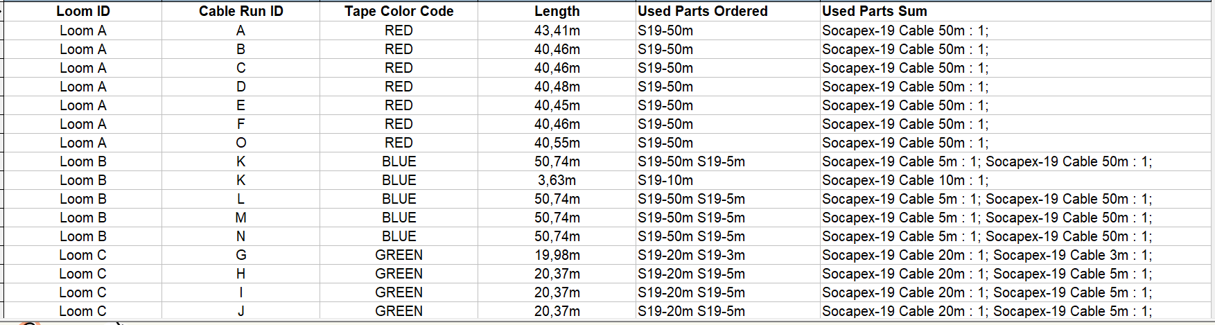
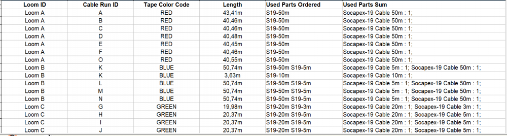
@Russ no problem, It helped me better understand the problem that needs to be addressed. A loom list is relatively easy to create, Loom List but as you pointed out in our discussion it is not possible to extract the info you need from it to create the cable stickers which include the length data (or other part specific data) on them. I will put an enhancement request in to have this addressed.
-
Instrument summary text disappearing Spotlight 2019 SP2
jcogdell replied to Oliver Hauser's topic in General Discussion
I'm on PC which may be why I can't replicate the issue. I'll open a bug report in for it.