
Tony Kostreski
-
Posts
194 -
Joined
-
Last visited
Content Type
Profiles
Forums
Events
Articles
Marionette
Store
Everything posted by Tony Kostreski
-
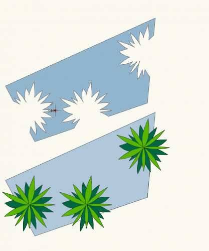
 Hi @jmccain8, That actually sounds like a great wish but not that I know of. If you really need just the negative space the only workaround I can think of is to select the Plant objects, duplicate them (so you don't lose the originals), and then run the command Modify>Convert>Convert to Group. You should be able to use Inner Boundary Mode with groups. Delete duplicate plant objects (groups) once finished. Here's my test. Let me know if that helps for now. I can put in a Vectorworks Enhancement to work with Plug-in Objects.
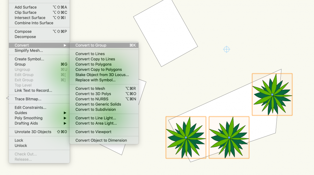
-
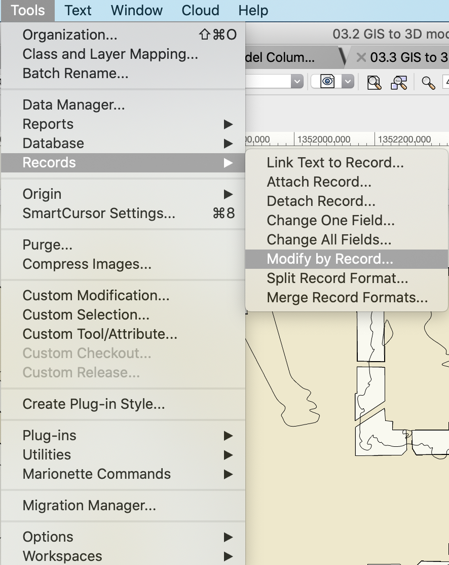
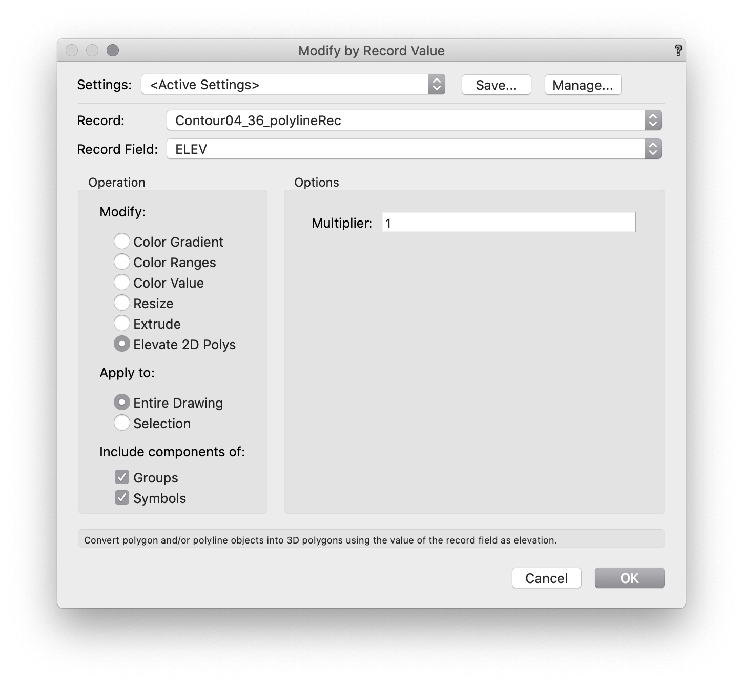
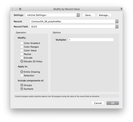
Hi @Benson Shaw Use the command Modify by Record found under Tools>Records>Modify by Record. Select the appropriate Record and Record Field and under Modify select Elevate 2D Polys. Modify by Record with shapefiles are a lot of fun! Another great example is extruding all buildings to their known height automatically 😉 or, EVEN BETTER, using this Marionette script, 2D to Massing Models, that converts them to Massing Models while maintaining their floor usage. Best wishes, Tony

-
@Laura Stone -- I agree and will bring this up internally again. For now, try using "pad" when you want a closed "contour". Don't forget to always use a "grade limit" as well! 😉
-
Hi @jpccrodrigues, I think this is a great wish. For the time being try ungrouping the landscape area -- this is a nice trick if you want the individual plant objects in 2D but NOTE you will lose the ability to adjust the overall shape of the landscape area as they will now be "x" number of plant objects instead. Afterward, you can select similar plants and change the plant grouping so they act as one object when placing labels. Hope this helps, for now! Tony
-
Correct import settings from an Archicad dwg file
Tony Kostreski replied to KarynT's topic in Site Design
Thank you, @KarynT! That means a lot. Yes, It would be a "save as..." and then "IFC file". This also retains all data associated to any object in the data tab of the object info palette. IFC (Industry Foundation Classes) is just a non-proprietary or open file format that allows for the exchange of 3d geometry and data. I just find it works best when exchanging between various software programs 😉 -
Correct import settings from an Archicad dwg file
Tony Kostreski replied to KarynT's topic in Site Design
@KarynT Have you tried importing an IFC file from Archicad? It works really well and might help with the issues you are having. -
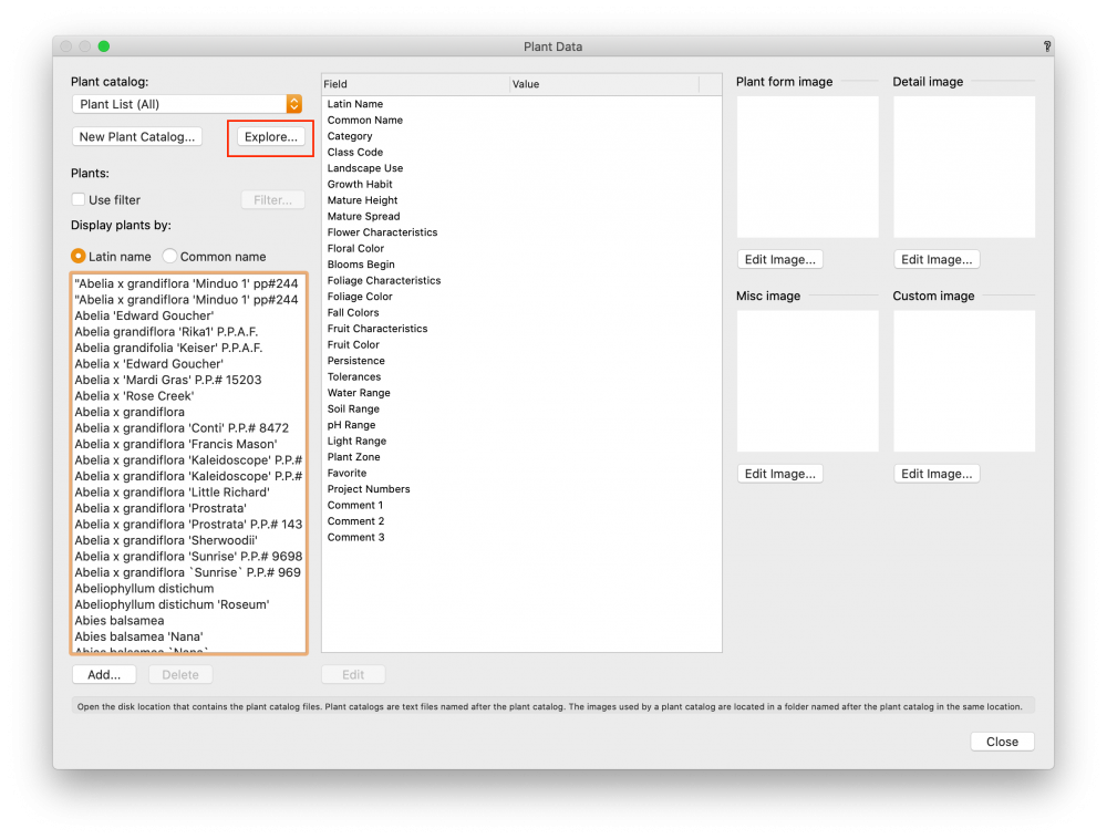
Hi @plantkind, Check out this webinar on The Power of 3D Modeling. In it, I used a small urban residential project I did when I was still practicing. I'm happy to discuss further with you if you'd like 😊. A good follow-up webinar is Save Time with Hardscapes & Data Tags. For minimizing toolsets check this The Basics: Tool Palettes and Workspaces. The Vectorworks University in general is a great resource. For plant libraries, you can import your own CSV file. Simply place this .csv or .txt file in the plant database folder. Easiest way to find this is open up the plant database in Vectorworks and select "Explore". Best wishes, Tony
-
I've done similar with multiview—one perspective view and one elevation (ortho mode) using nudge command 😉. Screen recording of just one screen.
-
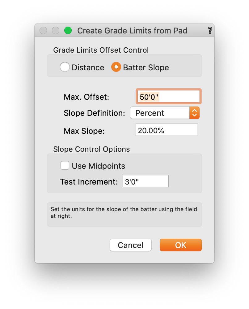
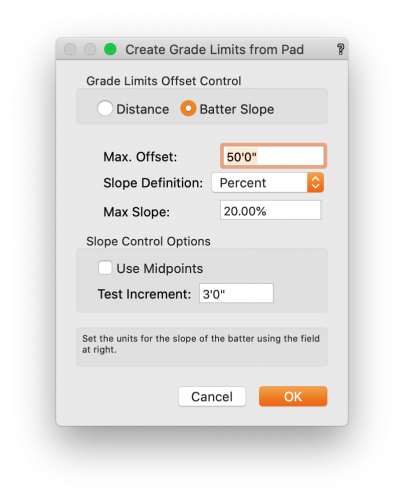
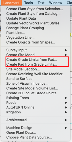
@Markvl Yes, using the grade limits mode for the site modifier is what you would want to use. You can also select the pad modifier and select the command "Create Grade Limits from Modifier" and specify a specific slope or distance 😉
-
A big benefit you gain from this workflow is you can take advantage of the Geoimage tool which let's you view satellite imagery/streetmaps directly in the software and the site model (in Vectorworks 2020) allows you to show Geoimage texture on the surface.
-
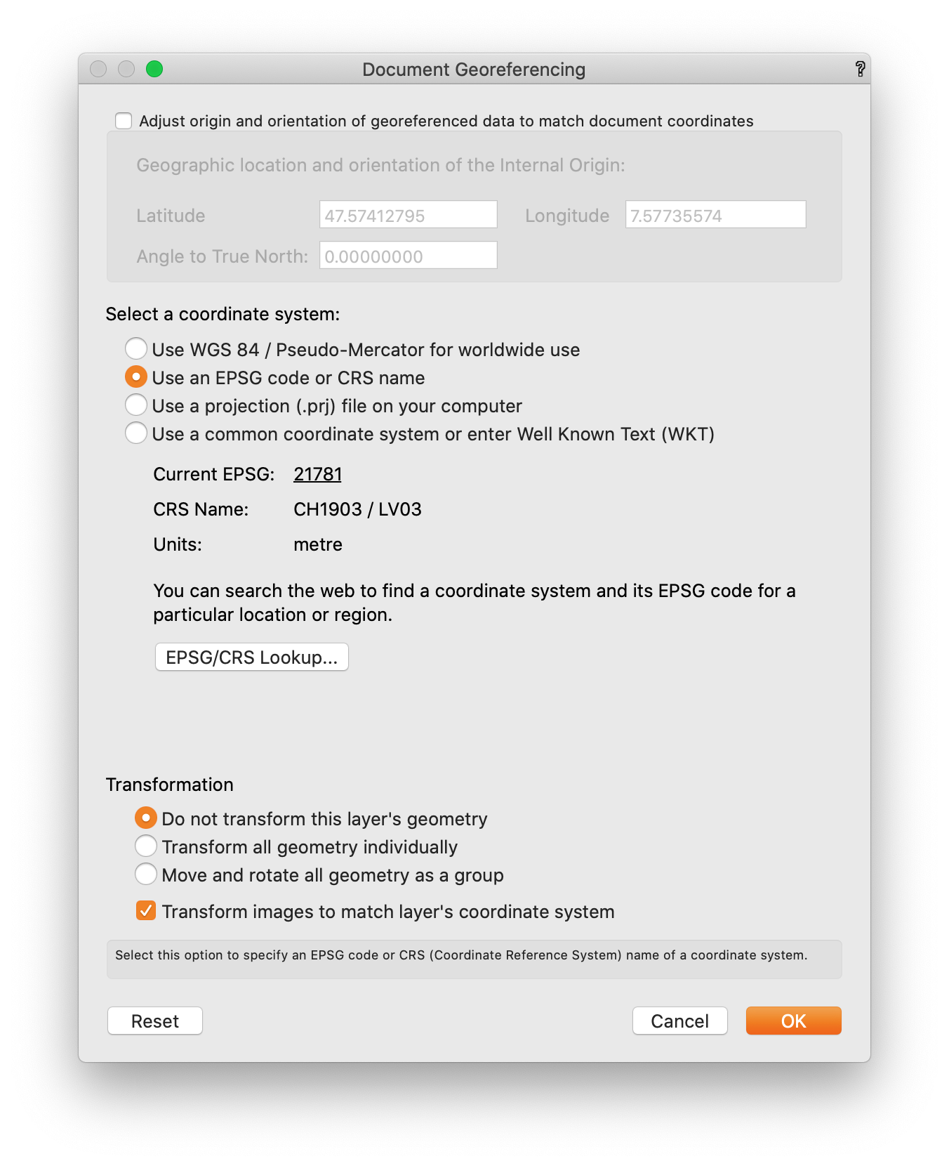
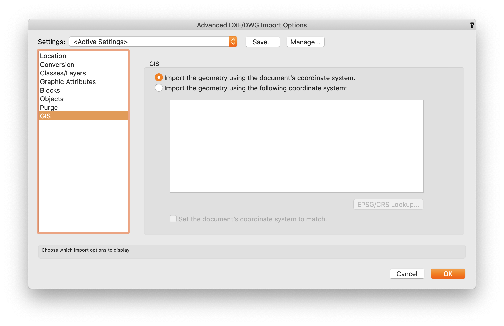
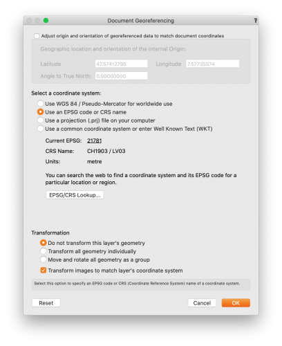
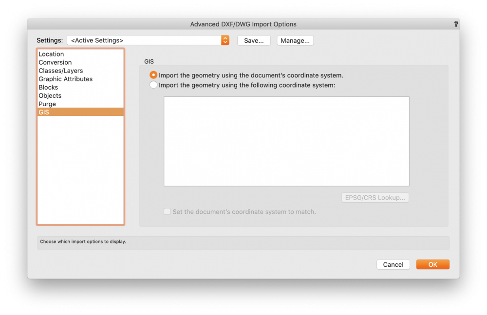
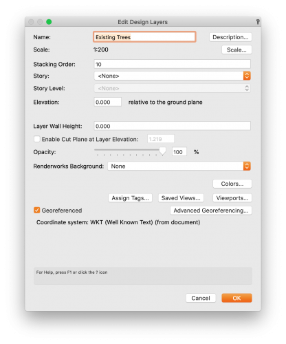
Yes, though to properly georeference you will FIRST want to set up Document Georeferencing—this can be found under File>Document Settings>Georeferencing. Select the appropriate coordinate reference system (CRS) used to generate the drawing you are importing—the civil engineer/surveyor should be able to provide this to you or you can search relative area under "EPSG/CRS Lookup..." though I do recommend getting the exact coordinate system used. Have "Adjust origin..." unchecked when setting this up. Afterwards, import the DWG importing with the method you described "This file contains georerefernced geometry". Make sure you use the following settings And lastly, make sure your design layers are Georeferenced.
-
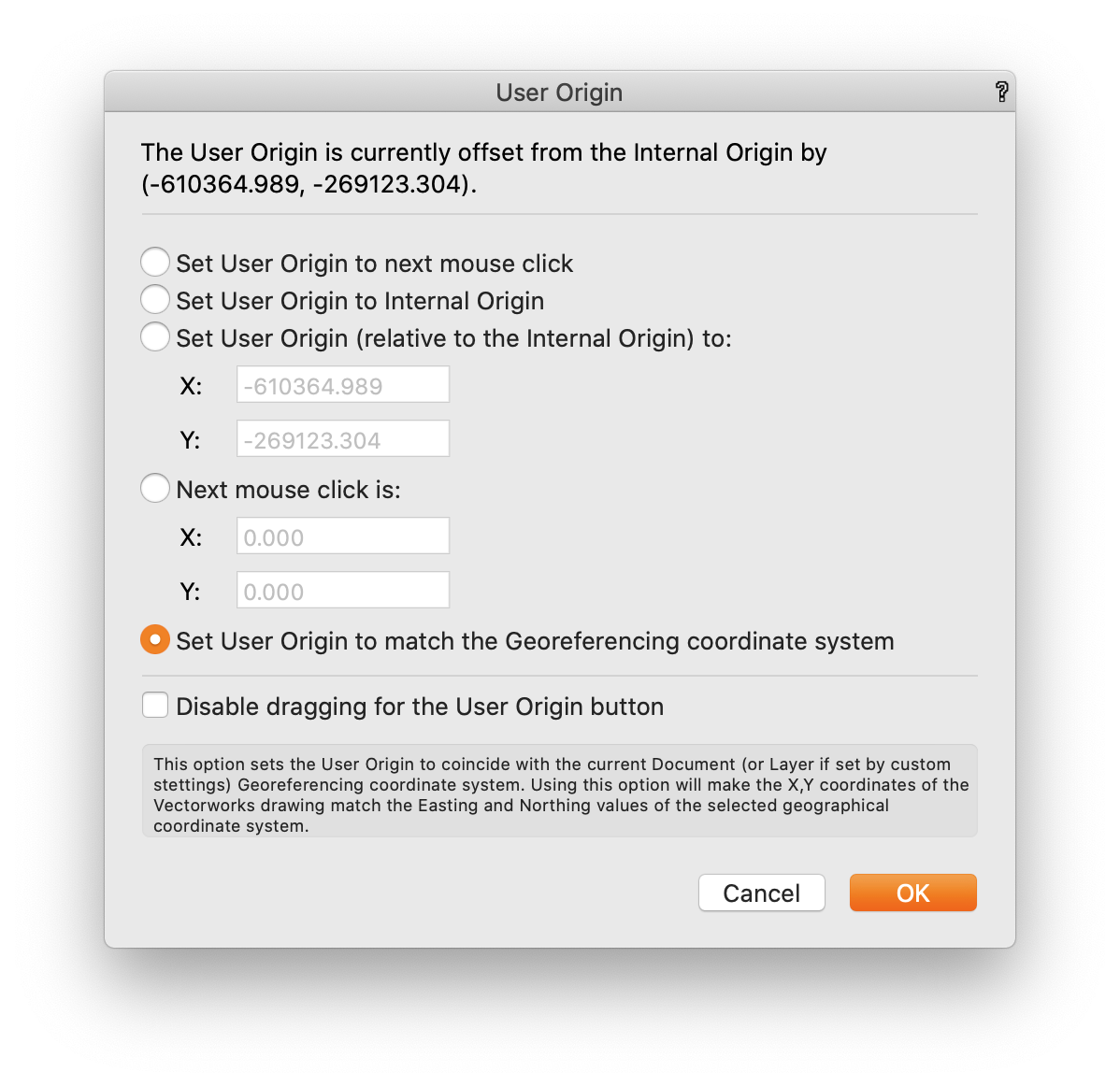
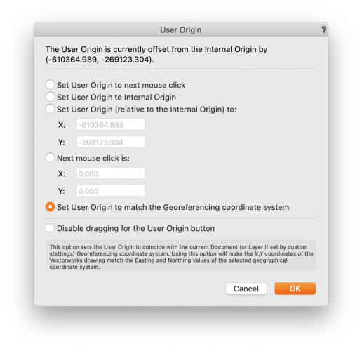
Hi @Anna Guzman-- Are you by any chance working far from the internal origin? I've seen this happen when working far from internal...you can check by going to Tools>Origin>Locate internal origin. If so, I would suggest working closer to the internal origin. In Vectorworks 2020 there is a new Geolocate tool that easily does this for. To maintain proper x,y coordinates you can then go to Tools>Origin>User Origin and select the last option "Set User Origin to match the Georeferencing coordinate system" I would also suggest creating the site model and massing models AFTER you perform the step above, otherwise they will remember their source data location. Hope this helps!
-
Hi @antonf26, It is a known bug, unfortunately. However, there is a patch for you to use that will fix your drawing. Please download the appropriate zip for your OS, and the file ‘Help Scripts.vwx’ from here: https://drive.google.com/drive/folders/1aC6XT2nePxrfNFYWLoIBjsvVvrT6w85B?usp=sharing Then unzip and replace the file from your Vectorworks 2020 installation with the file from the zip. The file ‘Help Scripts.vwx’ contains two help scripts that you must run inside your VWX files to fix them. The best way to do that, is to import the entire ‘Tools’ folder into your VWX file. Run the script ‘Adjust Plant Record’ which will fix the issue. And then you can run ‘Reset for Plant Record’ to reset all appropriate objects to pick up the change from the first script. Note, this operation might be slow, if you have another way to resetting, or you want to do it manually, you can skip the second script and just do it manually. Let me know if you have issues with this.
-
Dublicate Array command Presets
Tony Kostreski replied to markdd's question in Wishlist - Feature and Content Requests
Agreed! I think this is a great wish! -
Polygon Paint Bucket Doesn't Work in Section VPs
Tony Kostreski replied to willofmaine's question in Troubleshooting
Hi @willofmaine, What version of 2020 are you using? I noticed this in 2020 when it first came out but the issue has been resolved in SP1 I believe. Have you tried updating to the latest version? -
Site Modifiers (pad?) with varying heights along edge
Tony Kostreski replied to steve d.'s topic in Site Design
@steve d. just to confirm--your grade limit (limits of disturbance) is surrounding all site modifiers? It might help to see the file if you are willing to post it—even if it's simplified. If the roadway also has a grade limit try turning that one off as it might be conflicting with the other but hard to tell from an image. Good luck! -
@Kevin K I know this does not solve your issue exactly but figured I'd throw this out there anyways...If you use 3D Extruded Contours for the Site Model 3D Display Mode, the Clip Cube will treat it as a true solid (same with section viewports). When the Site Model 3D Display Style is set to Mesh, the Clip Cube reads the Site Model as a TIN element, and not a solid—I wish this were not the case. Thank you for your comment and I'll also raise your concern internally.
-
Yes, I would select "Recreate from source data", copy the source data, exit site model, and paste the source data in the right location (near the internal origin) outside of the site model. Then you can go ahead and "Create Site model" with the pasted source data and delete the old site model. (I hope this makes sense). How you created the site model from stake objects sounds correct. You can also create site models from 3D loci and 3d polygons. The x/y coordinates being high is typical when working with survey information and unless you don't have to send back out to say a civil engineer, I would keep the actual user origin. If you do not have to send the drawing back out for coordination purposes you can center the User Origin on the Internal Origin understanding the drawing will no longer be coordinated properly. One workflow would be to place a 2D locus point at the proper User Origin and only move the User Origin back to this 2D locus point when exporting DWG files.
-
Make sure the site model is created after the internal origin and user origin is set. If the site model was created beforehand it will retain the source data as being far away from the internal origin and thus have texture and geometry that is pixelated.
-
Hi @drelARCH, This tends to happen when you create a site model far away from the Internal Origin (not to be confused with the User Origin which dictates the x and y coordinates). Go to Tools>Origin>Locate Internal Origin to see if you are far. To fix the blurred/pixelated textures, you would need to work closer to the Internal Origin. To adjust a textures scale, mapping, or rotation on a surface you can use Attribute Mapping found in the Basic Tool palette. To understand origins a little better fast forward to 15:37 in this webinar recently posted Enhance Site File Collaboration with Georeferencing. Hope this helps! Tony
-
Hi @lisagravy, Try the modify dropdown menu. If it does not appear when right clicking (I believe you need to right click the upper most object), you can always add it by editing your workspace which can be found in the Landmark dropdown menu. Hope this helps!
-
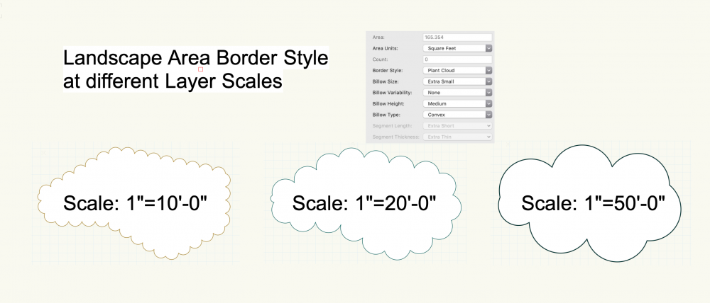
Hi @J. Wallace, Out of curiousity, I wanted to see if this was related to design layer scales—it seems like it is. The larger your Layer Scale is set (i.e. 1"=50'-0"), the less definition you get. See attached image for example of 3 different layer scales of the same landscape area with the same border style settings. I'm curious if this is new to 2019 and if so I can report a bug but in the meantime, I hope this helps! -Tony
-
Hi @NoemiM-- If you have the ability to get 3D surveys, the best thing to do (in my opinion) is to start by creating a site model. 3D loci (points) and 3D polygons can both be used as source data to Create Site Model. This command can be found under the Landmark dropdown menu>Create Site Model>Site Model From Source Data...Plants will automatically recognize the Site Model and land on the surface of the site model when drawing in top/plan view. For all other objects, you can use the Send to Surface command. You can either right-click the desired object>send to the surface or go to the Landmark dropdown menu>send to surface. NOTE: 2D objects (i.e. rectangles and polylines) when sent to the surface will convert to a 3D Polygon. This is useful when you start getting into site modifiers—another topic. I would refer back to the Getting Started Guides and watch the Site Model videos. Please keep the dialog going. I'm curious to hear about other workflows.
-
Getting Hard Landscape Levels Right
Tony Kostreski replied to Michal Zarzecki's question in Wishlist - Feature and Content Requests
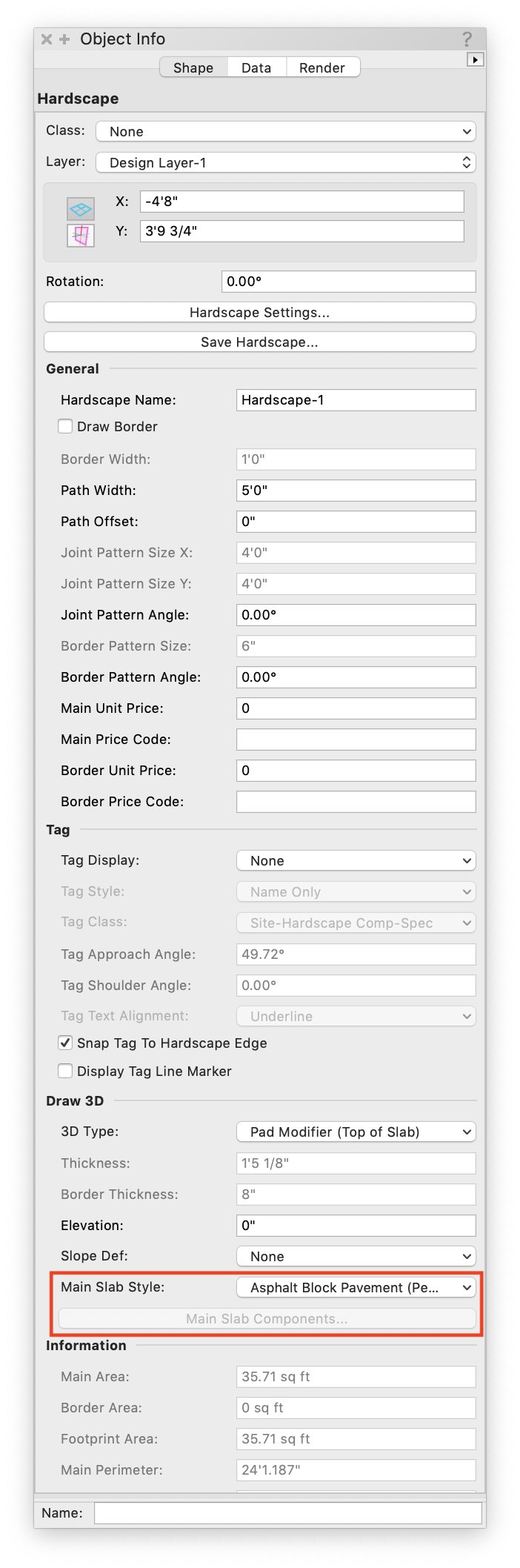
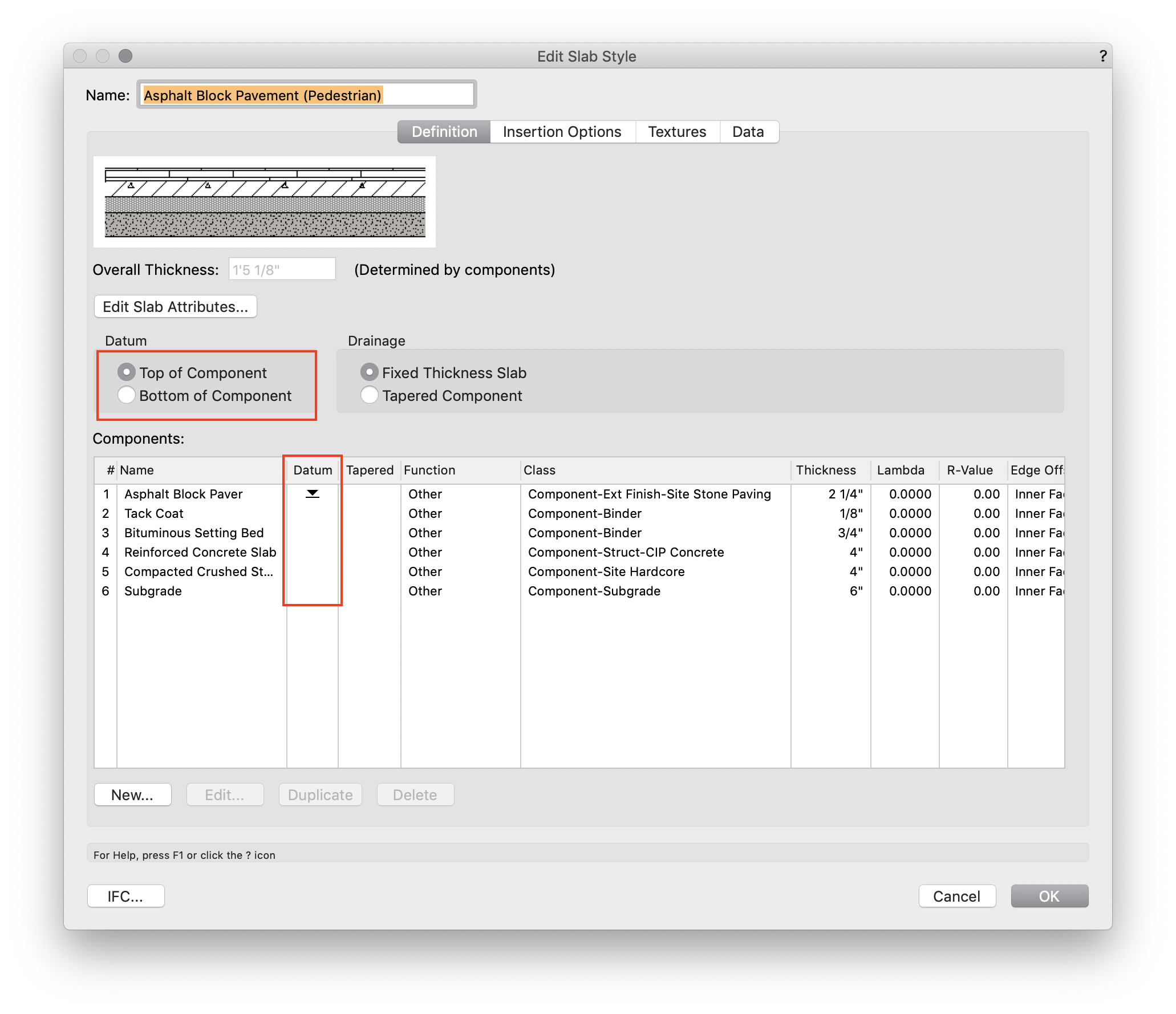
Hi @Pan.Gad, In regard to Hardscape Objects, check the "Main Slab Components" or the "Slab Style" in the Object Info Palette (OIP) and make sure you're settings are set to "Top of Component" (see images attached ). If Main Slab Components is greyed out in the OIP, select the Slab Style > "Edit Slab Style" and make the necessary changes the "Datum". I agree that the default should always be Top of Component since that's what we use for reference when designing. As far as the Stair Object goes, I agree that you should be able to input top of stairs (TS) and bottom of stairs (BS). Hope this helps! Best, Tony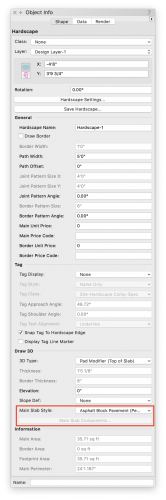

-
Hi @KarynT, I'm curious to know what it is you are trying to accomplish. Can you elaborate? The purpose of plant massing checkbox is to remove interior linework though you can keep tick marks if desired. If your goal is to have a thicker line that encompasses the plant grouping but interior linework remains I would suggest unchecking plant massing and setting the 2D attributes of the plant object to a thicker line. I recommend setting this by class...one set for trees and another for shrubs/perennials. Just make sure that under Visualization in the Object Info Palette that you have the appropriate Mass Outline selected (i.e. Tight Outline). Hope this helps! -Tony