
Tony Kostreski
-
Posts
194 -
Joined
-
Last visited
Content Type
Profiles
Forums
Events
Articles
Marionette
Store
Everything posted by Tony Kostreski
-

Problem with Orientation of North Arrow in a Viewport
Tony Kostreski replied to ashot's topic in General Discussion
Hmm...perhaps I am not seeing the problem or maybe it was a bug that has been addressed. This video is what I am seeing and it seems to be working fine for me. Selecting the checkbox for the heliodon simply orients the north arrow in the correct direction. Is this not the case for you? If so, what build are you using and I'll investigate further. Thanks! North Arrow Viewport.mp4 -
Problem with Orientation of North Arrow in a Viewport
Tony Kostreski replied to ashot's topic in General Discussion
Hey @ericjhberg! I have to agree that it would be nice to have the north point of a titleblock link to a viewports rotation. I'll submit a VE but in the meantime, I would suggest placing the north arrow directly in the annotations part of a viewport making sure to check "Use Heliodon". Like that you know the north arrow will point in the right direction automatically. What would you want to happen in cases where you have multiple viewports on a sheet? Have you ever had more than one north arrow (pointing different directions) on a single sheet?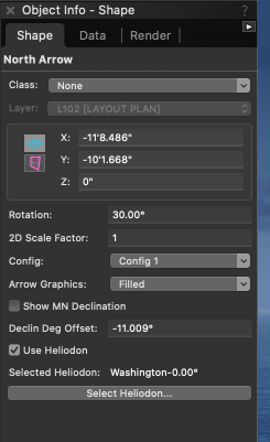
-
Site Model - Lock in Place
Tony Kostreski replied to ericjhberg's question in Wishlist - Feature and Content Requests
@ericjhberg —good wish. I've noticed how sensitive the site model is to accidental selection & movement. For internal reference, VE submitted (VE-101351) -
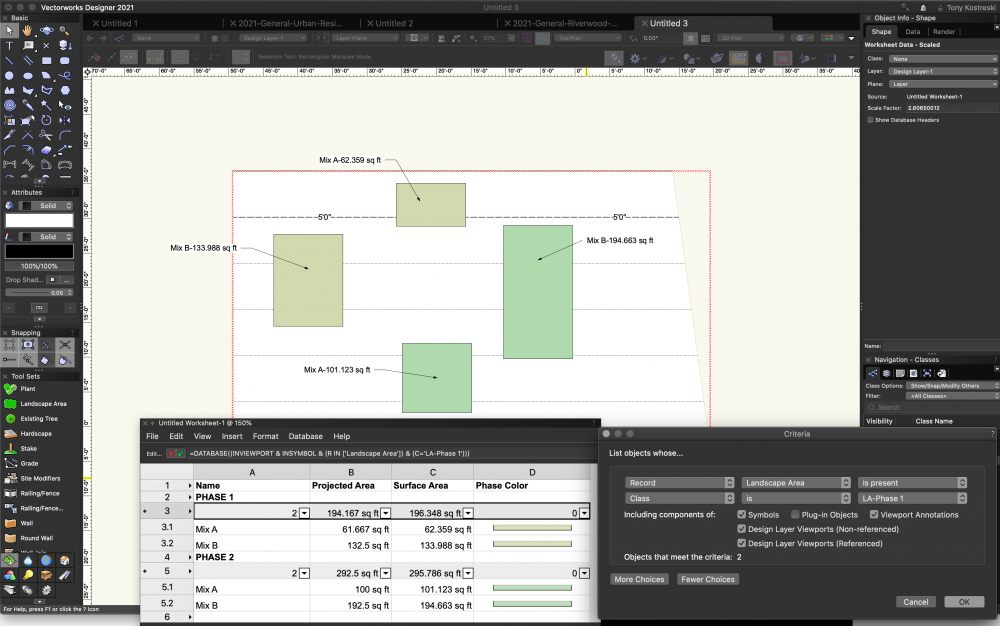
Hey @alfresco, Let me know if this image helps. You can edit the criteria of each database header to select a class. Landscape areas are special in which you can pull projected area and surface area if a site model exists.
-
@KristjanT--very strange... By any chance did you move the site model after creating it? If so, the source data would retain original location and might be the culprit when exporting to IFC (this is just a guess). You could try recreating the site model in the correct place, not move it, and export it again. Happy to look at the file if problem persists 🙂
-
Set up layers with different z values
Tony Kostreski replied to Loraine Hourdebaigt's topic in Site Design
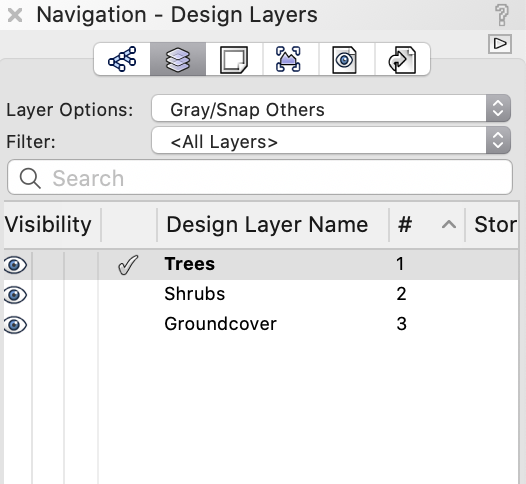
Hi @Loraine Hourdebaigt--you can edit the design layer's elevation. Simply right click on the design layer and select Edit. Change the value under Elevation. Hope this helps!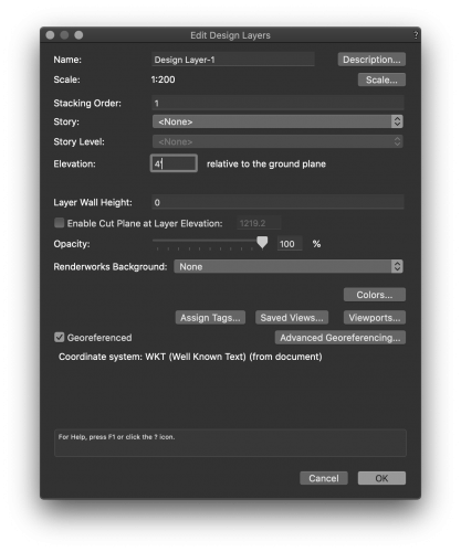
-
Kerb/Edging Tool
Tony Kostreski replied to Laura Stone's question in Wishlist - Feature and Content Requests
Completely agree. I have posted an enhancement request VE-101278 (internal link for Vectorworks staff) -
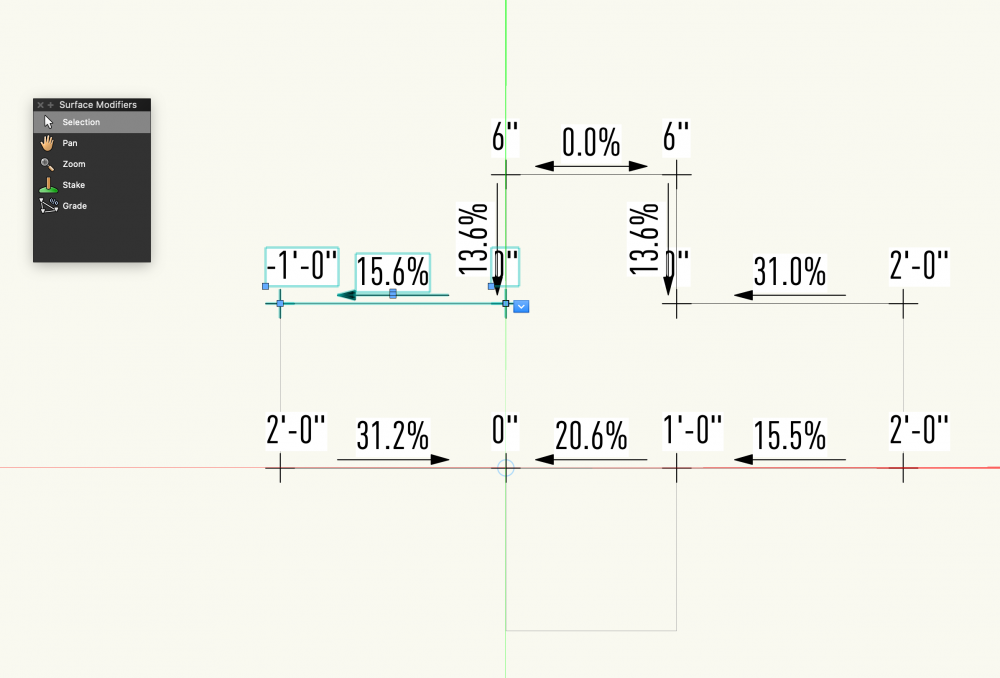
Hey @Siddharth, Have you tried using surface modifiers within an aligned hardscape? You can use grade objects and in 2021 these grade objects can be linked to create a network. After you set the grade objects up, I will suggest unchecking "Interpolate Surface" in the object info palette. Attached is a super rough example.
-
Hey @line-weight, I recommend using two separate design layers. In the Site Model Settings under General, select "Use Site Modifiers on:" and select the appropriate design layers. You can simply move what you've created to a new design layer so no time is really wasted 😉 Hope this helps!
-
Hey @DDD Try removing the setting for "Top: Quantity-ID" since the "Bubble" setting already does that for you.
-
Trouble switching off plant tags separately in viewport
Tony Kostreski replied to Heidi's topic in Site Design
Hi Heidi, If the plant tags are on class "plant-component-tag" simply turn the visibility of the class on/off in the Navigation palette. If it's on a sheet layer, this can be done through the viewport>class settings. Assuming your plant symbols are on a different class (i.e. plants-proposed), this should work. I recommend taking a look at Data Tags—very powerful! There are some preconfigured plant tags but they can certainly be customized 😉 Tony -
Hi @Heidi In addition to what Bryan mentioned, Viewports have visibility control over layers/classes so if your plants have a fill/gradient on them you can turn off its visibility as well. If you're using Vectorworks sample plants the class is Plants-Component-Fill. Hope this helps!
-
Hi @hollister design Studio, This is a great wish! I often just drew them manually as you show but it would be great if the polygon display had its own ability to be reshaped. Vectorworks Enhancement has been submitted. Internal VE-101224 Thanks, Tony
-
Is there any way to add in additional fields in a Plant symbol?
Tony Kostreski replied to Flora 9088's topic in Site Design
@ericjhberg I agree and I'll put in a formal enhancement request. Thank you -
Landscape Areas - Fill and Pen Opacity
Tony Kostreski replied to loretta.at.large's question in Wishlist - Feature and Content Requests
Hey @loretta.at.large – Thanks for sharing! I have to agree–I've submitted a formal enhancement request VE-101126.- 3 replies
-
- 5
-

-
- site design
- landmark
- (and 3 more)
-
Is there any way to add in additional fields in a Plant symbol?
Tony Kostreski replied to Flora 9088's topic in Site Design
@Flora 9088 - At present, I don't believe there is an option similar to Existing Trees' "Additional Fields". Instead, I would look into Creating record formats which can be attached to symbols & objects. You can then Create Reports that look for these records. -
Better gray backgrounds
Tony Kostreski replied to P Retondo's question in Wishlist - Feature and Content Requests
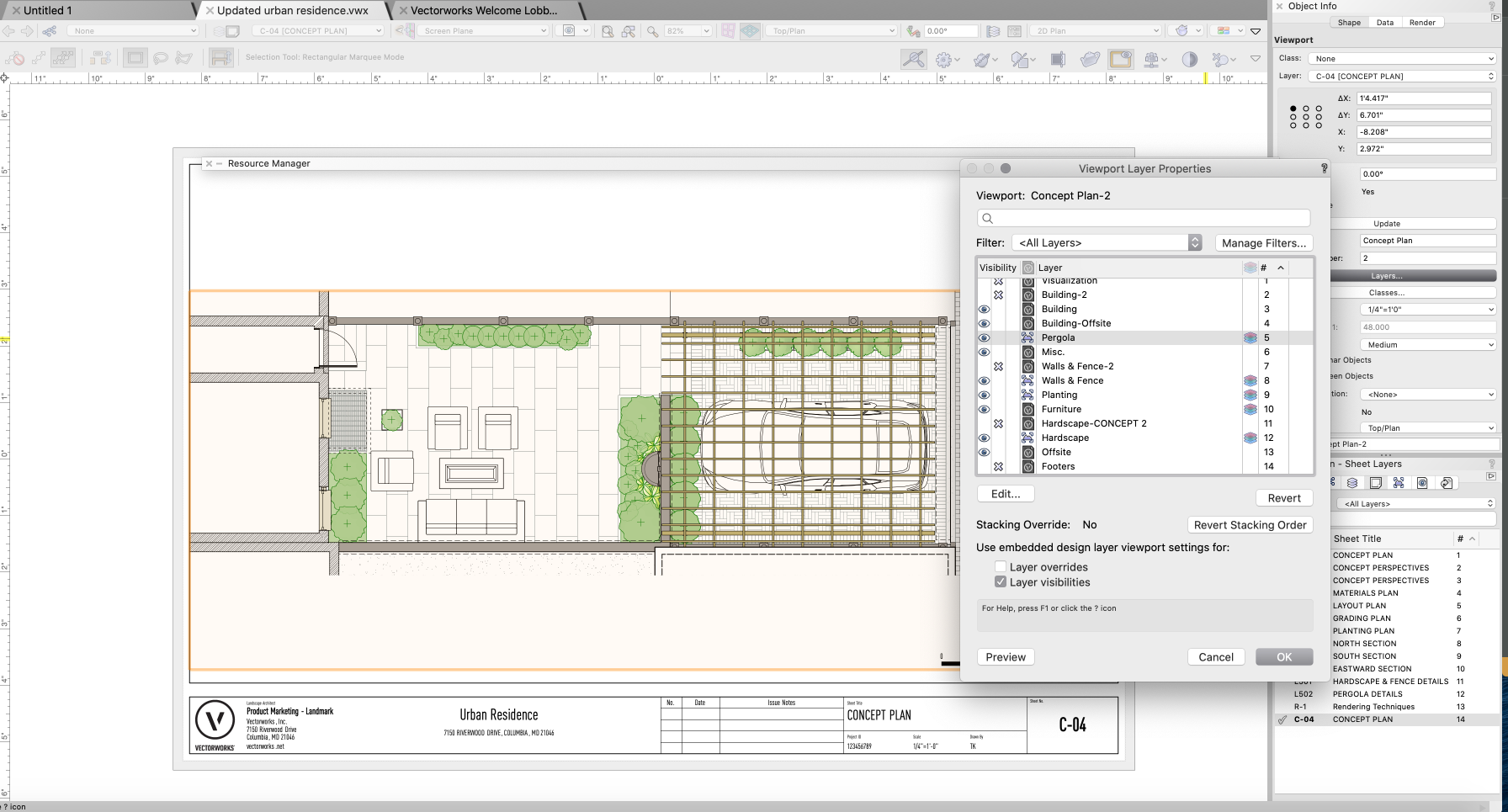
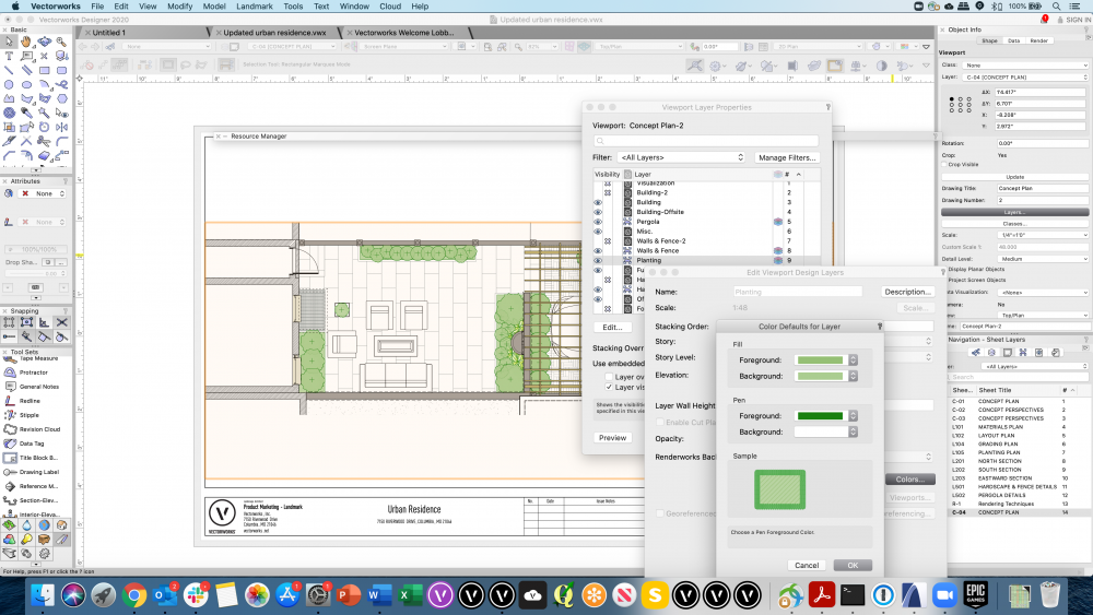
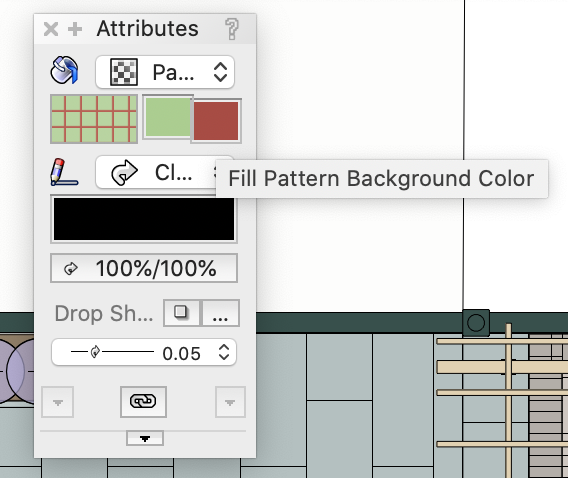
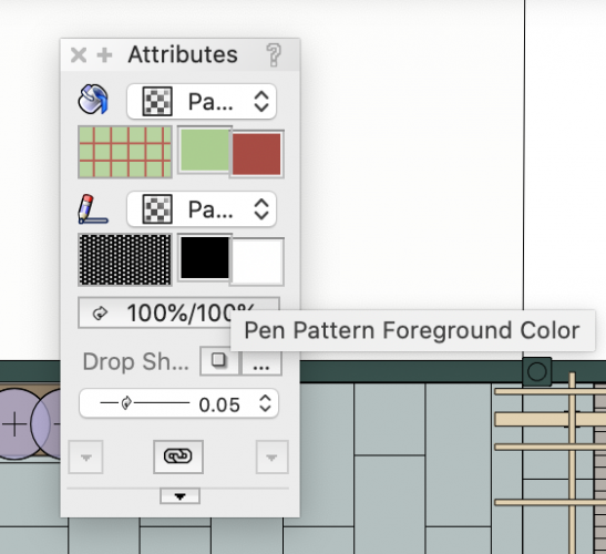
@P Retondo My apologies as I should have listed some additional info... Do not use Layer Colors in Design Layer workspace. Instead, use Viewport Layer Properties to enable Design Layer Colors and override them to your liking. Please see the attached examples When you select Viewport Layer you get the Viewport Layer Properties dialog box. You can turn them on or off by selecting the column next to the number (they look like stacked color layers). You can edit any of these design layers to set a specific color. See this example In this example, the fill was set to a green with a darker green pen—you can use whichever color you'd like. NOTE: I recommend using Background for Fill and Foreground for Pen. These both exist in case you use Patterns in your drawing for 2d attributes. Happy to hop on a call if you want to walkthrough this further. Please let me know if you have any other questions. Cheers! Tony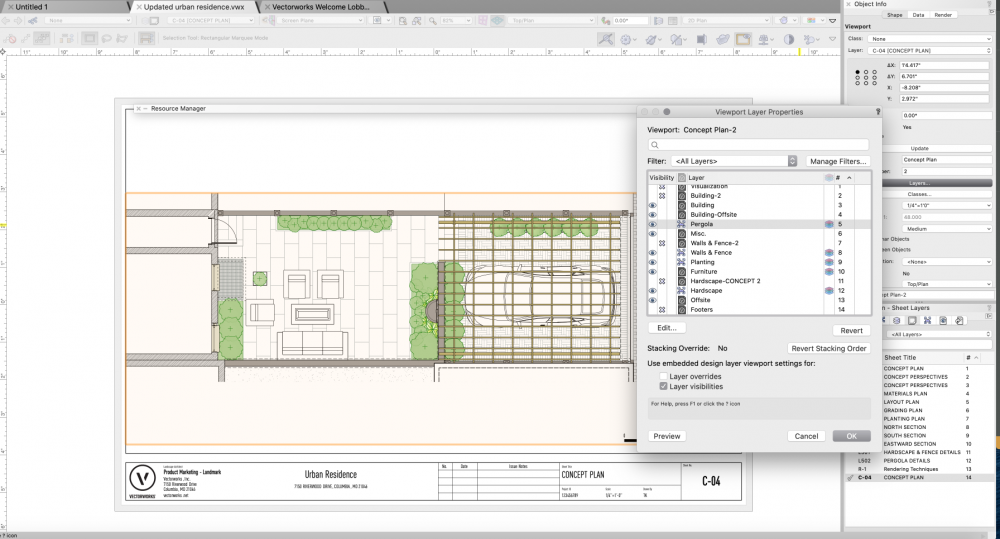
-
Better gray backgrounds
Tony Kostreski replied to P Retondo's question in Wishlist - Feature and Content Requests
Hi @P Retondo-- Have you ever tried Layer Colors out of curiosity? This is a very old video but still valid IMO You can essentially assign colors to specific layers (i.e. any kind of gray you want) to both fill and pen. This avoids the problem of creating "see-through" or "xray" elements. I hope this is an option that helps! 😊 -
Hi @Landartma, I would suggest creating custom record formats—they're great! Check out this webinar (Hardscape & Data Tags) and fastforward to 42:03. I talk about how to create custom records, attach them to ANY object, and later can be pulled into Data Tags and/or Worksheets (at the end). Please let me know if you have any questions still after seeing it. Best, Tony
-
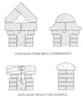
@DBrown @rDesign @jeff prince I too agree for the need of stacked walls. I'd love to hear what requirements you envision so I can bring them up internally, if you're willing to share. As a fellow landscape architect, here are some of my quick thoughts to start the conversation: Unlimited Layers (ability to offset each) Define Footers Define Wall Caps (by profile including complex shapes that involve multiple objects such as the case with brick caps) & Wall Cap Ends Define Batter Thank you, Tony

-
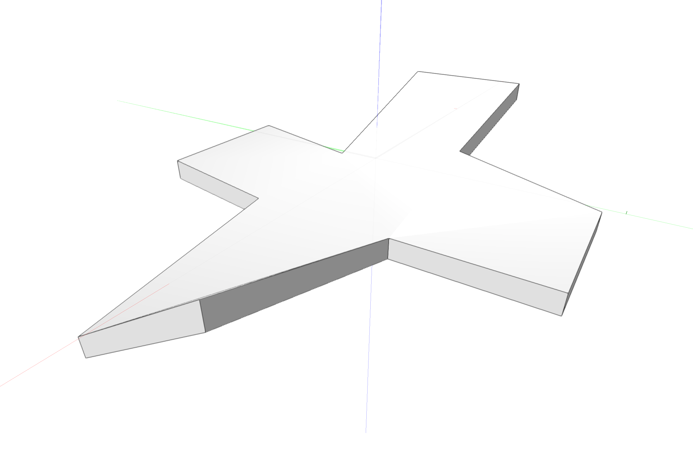
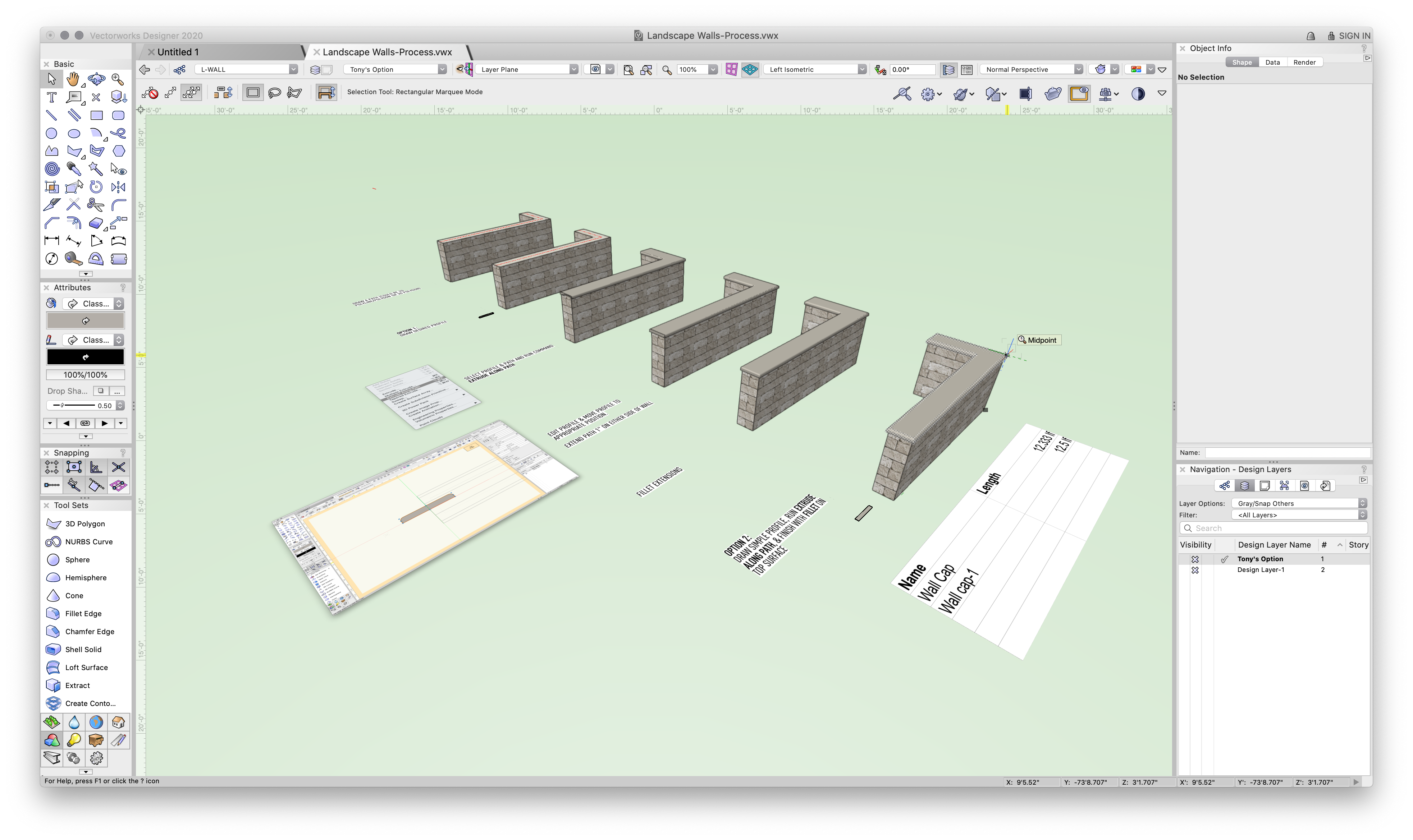
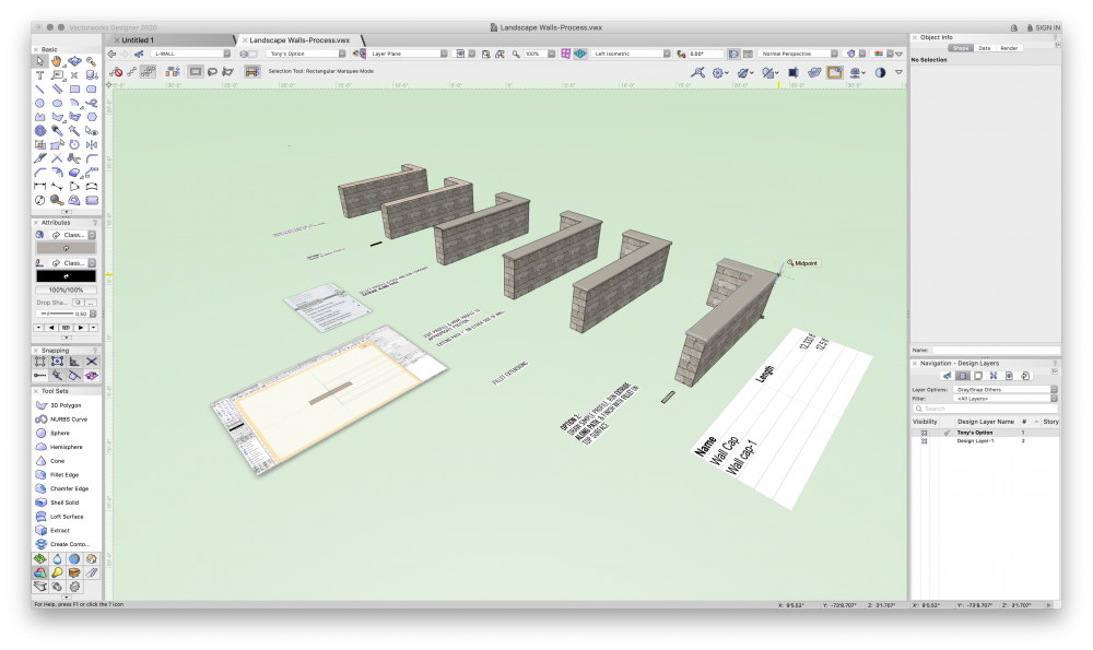
HEY @jeff prince, Have you tried using "Extrude Along Path"? I find it useful for creating specific profiles and paths, both of which can be edited at anytime. See attached file and let me know if you have questions. Start from the top and work your way down. I've included two options for getting the bullnose effect. And for Extrude Along Path objects you can pull LF into worksheets if that helps. Landscape Walls-Process.vwx
-
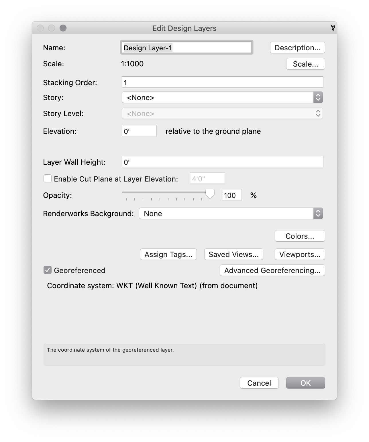
Need help with Georef imports, please
Tony Kostreski replied to Ned Daugherty's topic in General Discussion
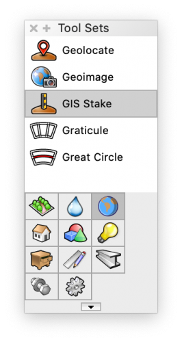
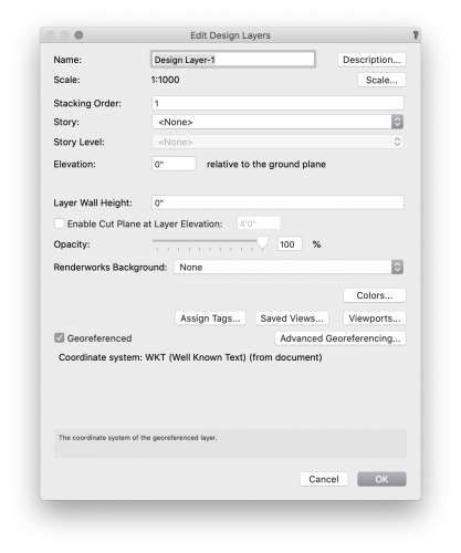
Hi @Ned Daugherty, Looking good! I recommend using the GIS Stake tool if that's not what you were using. At the very bottom of the Object Info Palette, there is a button for Set Geolocation. I would confirm layer scale is set to the same as the survey import and also make sure the Georeferenced is "checked" in the design layer settings. Vectorworks 2020 Help: Importing Survey Data. If you're willing, I'd be happy to take a look at the survey file and also discuss internally to see how we can come up with a solution.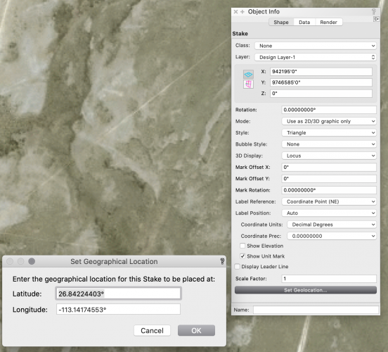
- 1 reply
-
- 1
-
-
Hi @BGD, This is where Design Layers come in handy—they are stackable and keep objects in place (in top/plan) so there is not need to "send to back/front". There are a number of techniques I've seen and it all depends on your preferred output. In the most simplistic form, try this:
-
drop down tree onto terrain levels
Tony Kostreski replied to Christian Fekete's topic in Site Design
If you're using the Plant tool it will automatically recognize the terrain surface. For all other objects (including VB Visual Plants) use the Send to Surface command. Depending on your workspace it's either AEC>Terrain>Send to surface or Landmark>Send to Surface. -
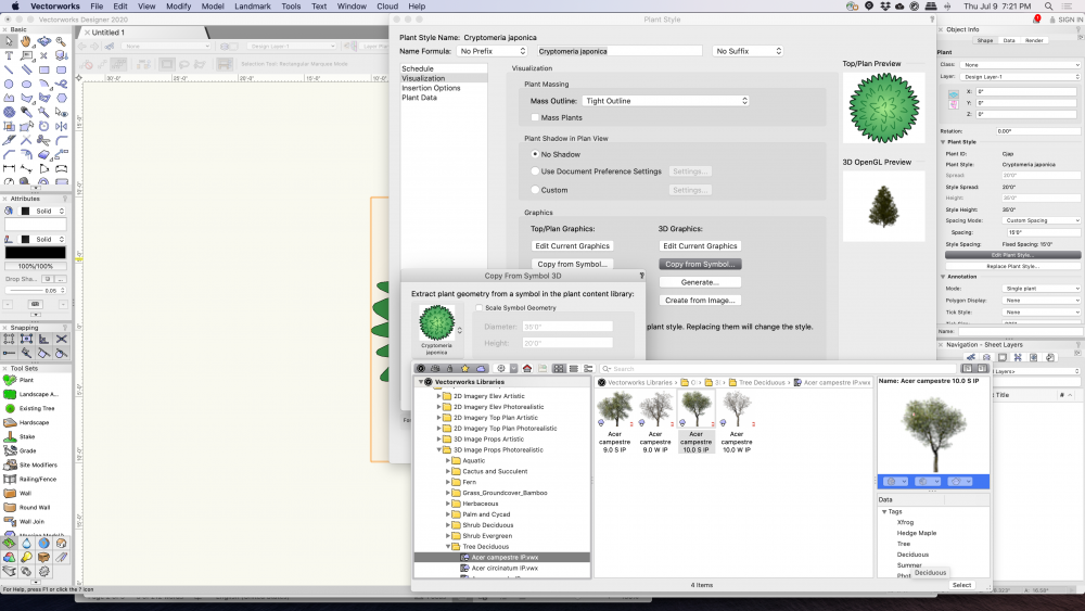
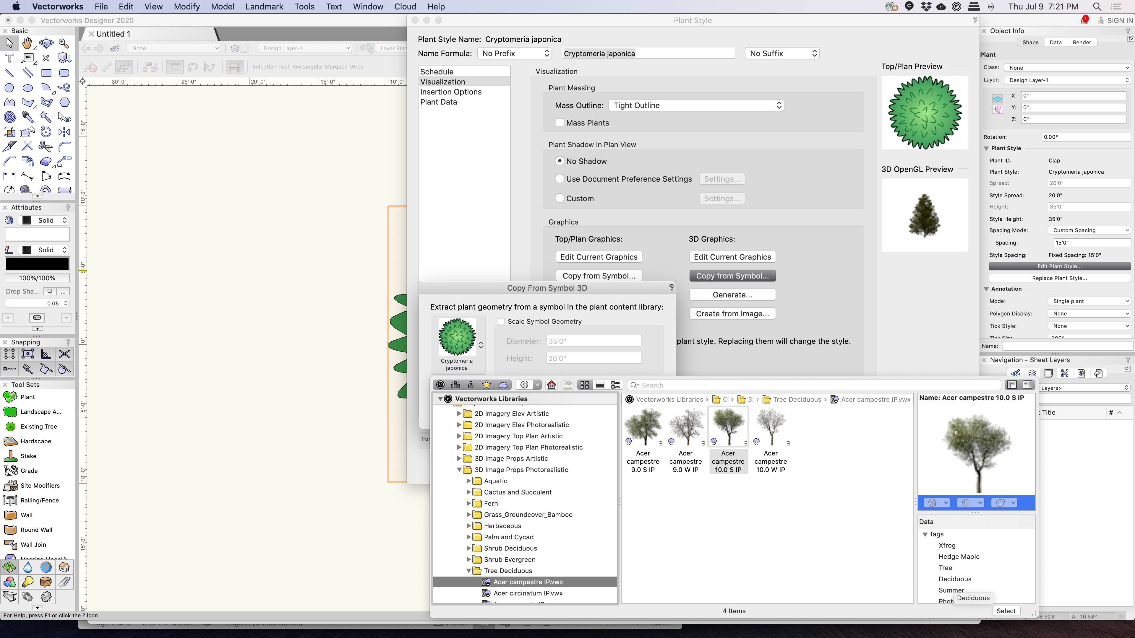
Hi @BGD-- Please let me know if this answers your question: Edit Plant Style>Visualization>3D Graphics>Copy from Symbol>Find desired 3D image prop photorealistic.