
Tony Kostreski
-
Posts
194 -
Joined
-
Last visited
Content Type
Profiles
Forums
Events
Articles
Marionette
Store
Everything posted by Tony Kostreski
-

Advanced Scale tool
Tony Kostreski replied to Marnix Kasper's question in Wishlist - Feature and Content Requests
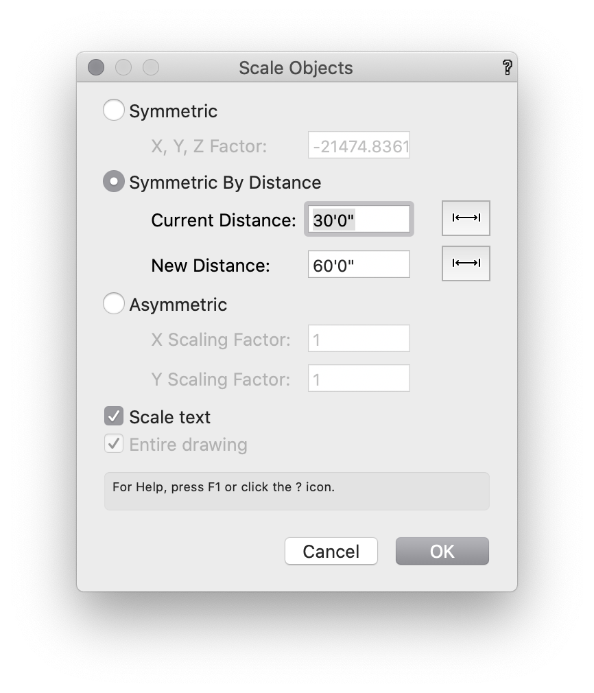
Modify>Scale Objects. 2nd mode "symmetric by distance"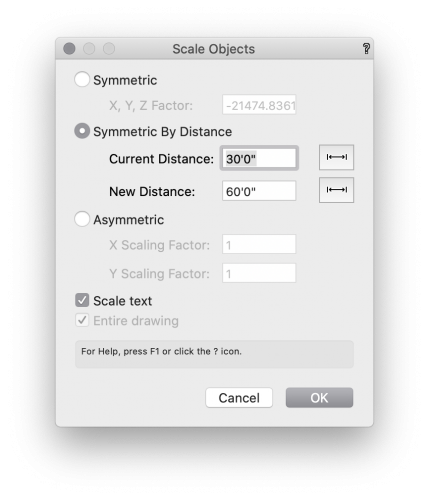
-
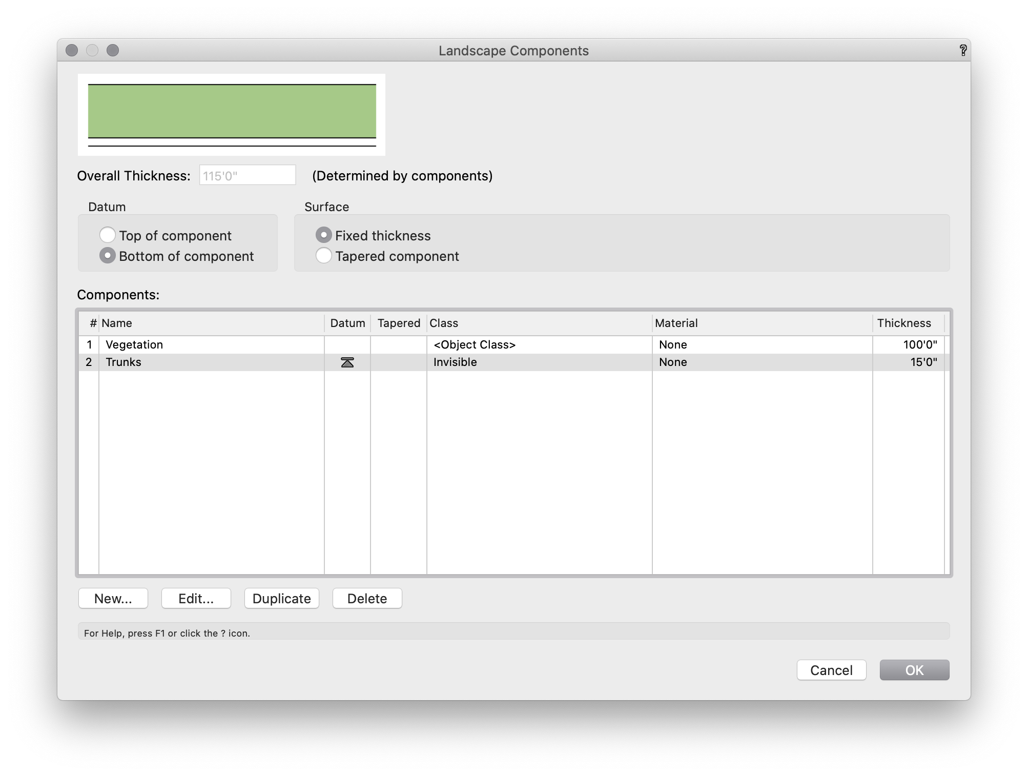
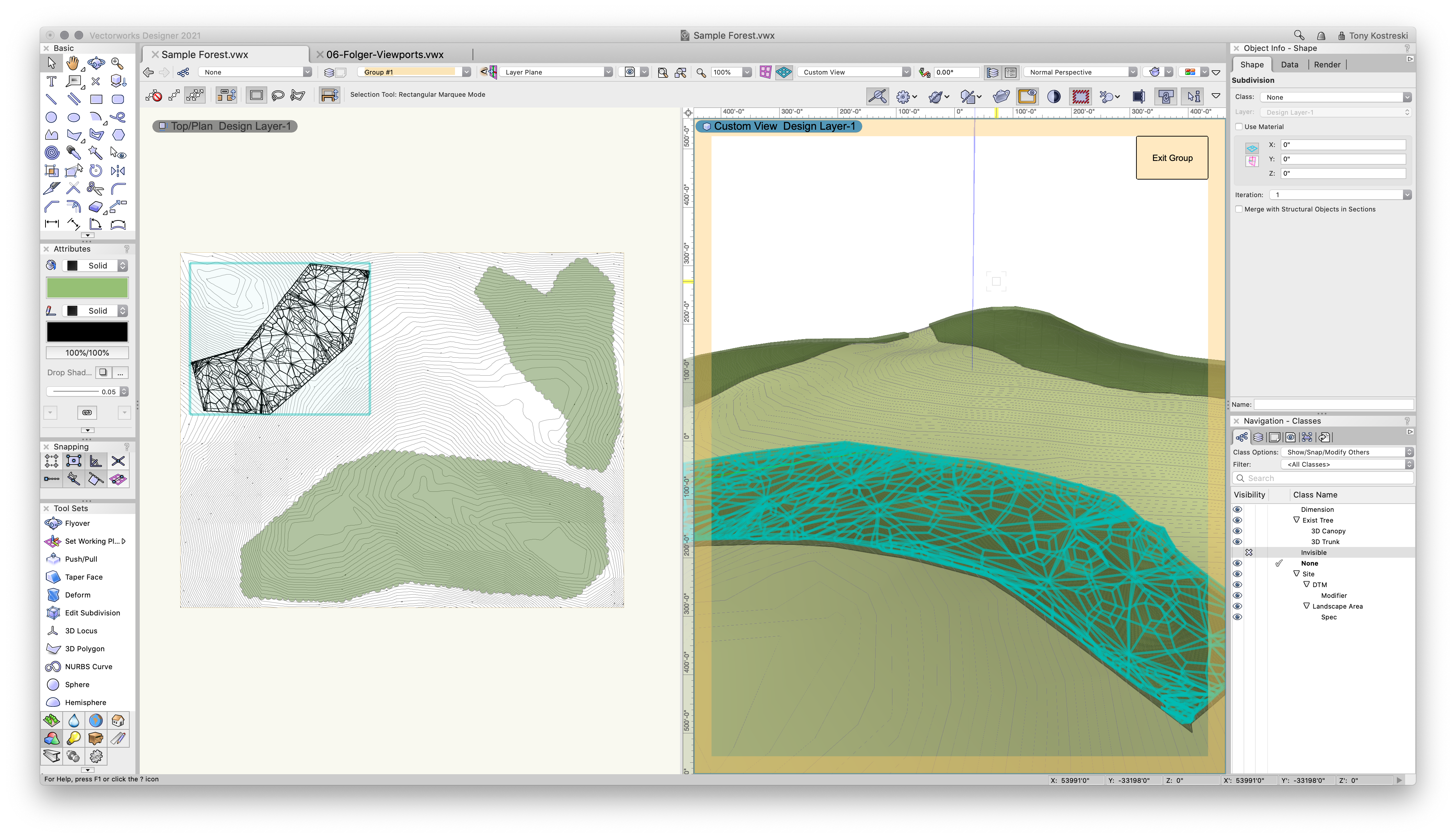
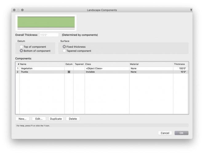
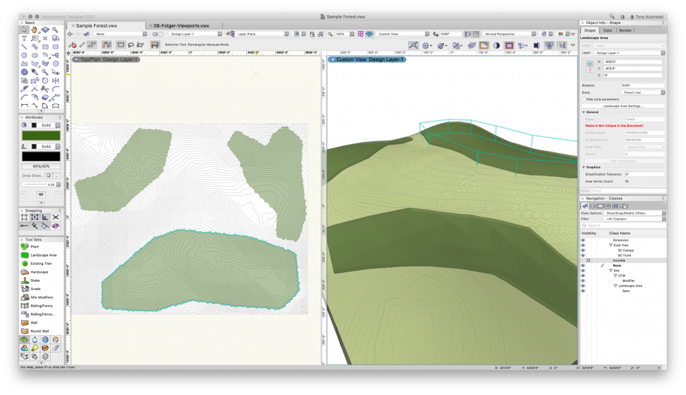
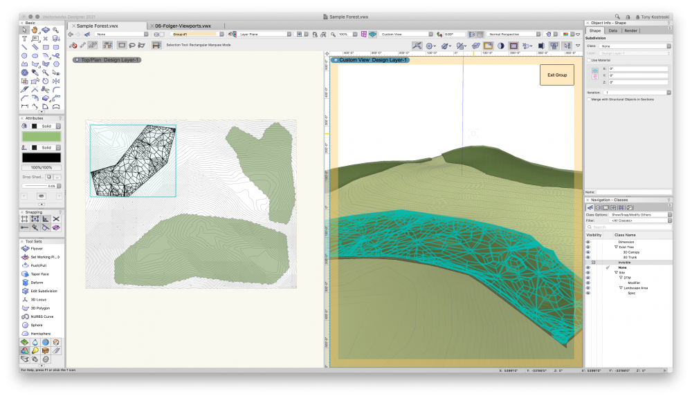
Hi @lisagravy, Now...I'm not entirely sure this is exactly what you are looking for but taking a stab since I thought this was an interesting question 🙂 I did opt to use landscape area to represent forest massing, not including plants but instead using 3D components. Very simple. 2 Components: Trunks and Vegetation (or Canopy). I applied the "ET Canopy Texture" since it has opacity but you can use any texture. The polygon representing forest is converted to a 'Landscape Area' using my 'Forest Line' LA style. It uses a cloud representation for 2D. This will very quickly get you 3D geometry to match to the surface of terrain (site model). This might be good enough but I explored some more. Landscape areas can be ungrouped which will give you a mesh. This mesh can be converted to a Subdivision allowing us to sculpt it to give it some varying height if this is for visual purposes. Note: you lose the landscape area if you need that for area calculations. Let me know your thoughts on this. Attached is the sample file.Sample Forest.vwx Best, Tony

-
Twinmotion or Sim. For Mac
Tony Kostreski replied to Greggoid's question in Wishlist - Feature and Content Requests
@Greggoid I forgot to mention we made our Roadmap public so follow along 😉 https://blog.vectorworks.net/roadmap-follow-along-with-the-development-of-vectorworks-design-software Take a look at what's in development 😉
-
Twinmotion or Sim. For Mac
Tony Kostreski replied to Greggoid's question in Wishlist - Feature and Content Requests
A direct link would be great but have you tried this workflow yet? https://university.vectorworks.net/course/view.php?id=789 Export to Unreal Datasmith was made available in Vectorworks 2021 SP3. -
Gradient Cut Fill Site Model Visualization
Tony Kostreski replied to ericjhberg's question in Wishlist - Feature and Content Requests
Interesting idea 🙂 Do you envision this working through the settings of the site model or through data visualization @ericjhberg? For internal reference, a VE has been submitted (VE-101778) -
I agree it should be easier to get to this point. Make sure to "Save Site Model Settings" so you're really only setting up how Site Models are created once. You can save this to your template so that it automatically creates those classes. You can even save multiple different Site Model settings depending on what's required for the project. I think adding a button to the OIP is a nice wish — I'll submit a Vectorworks Enhancement.
-
Hey @hollister design Studio, I just did the same test and it works on my end. Did you set the class to "use at creation" and in the site model settings all attributes are "set by class"? Here is a sample fileSite Model-contours off.vwx Turn the visibility of class "contour labels" off. Let me know if you get it working. Best, Tony
-
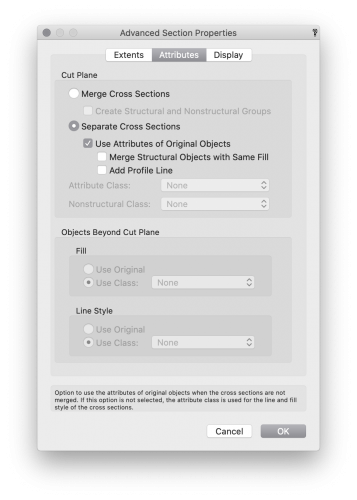
Hey @NickLeslie, What are your Advance Section Properties>Attributes set to? Make sure checkbox for Use Attributes of Original Objects is selected. If that does not work, feel free to drop a sample file and I can investigate further.
-
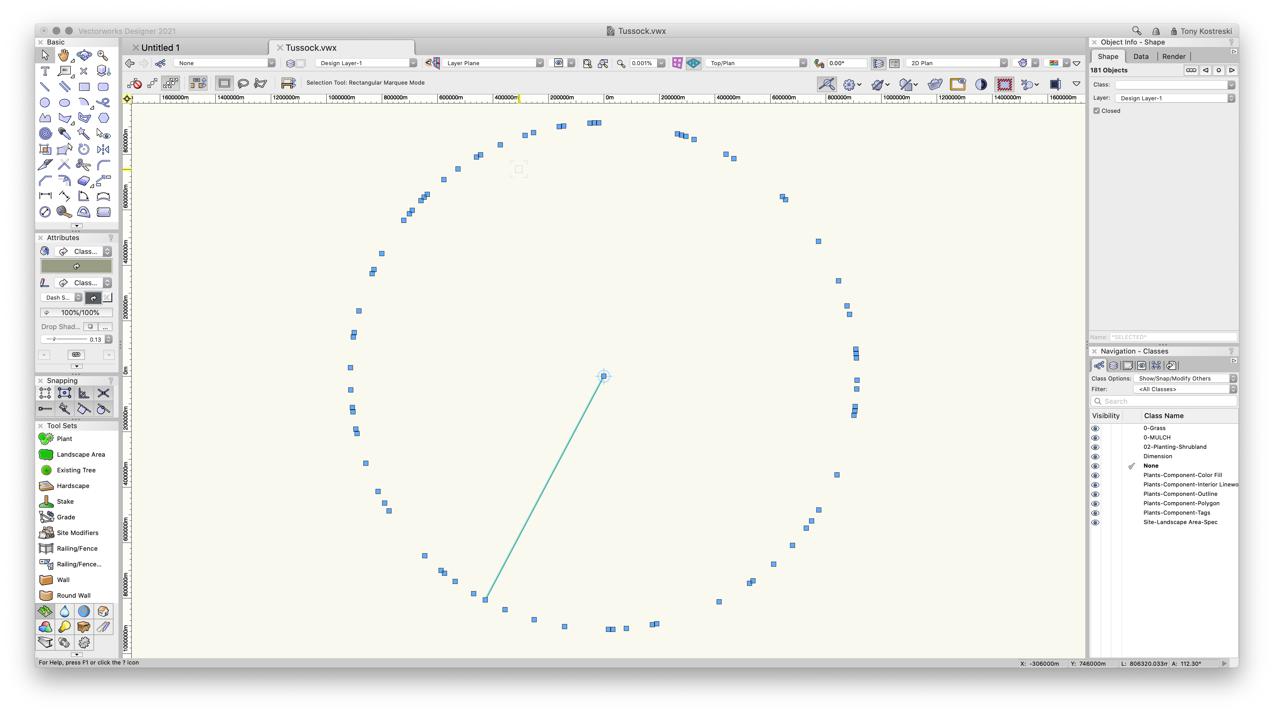
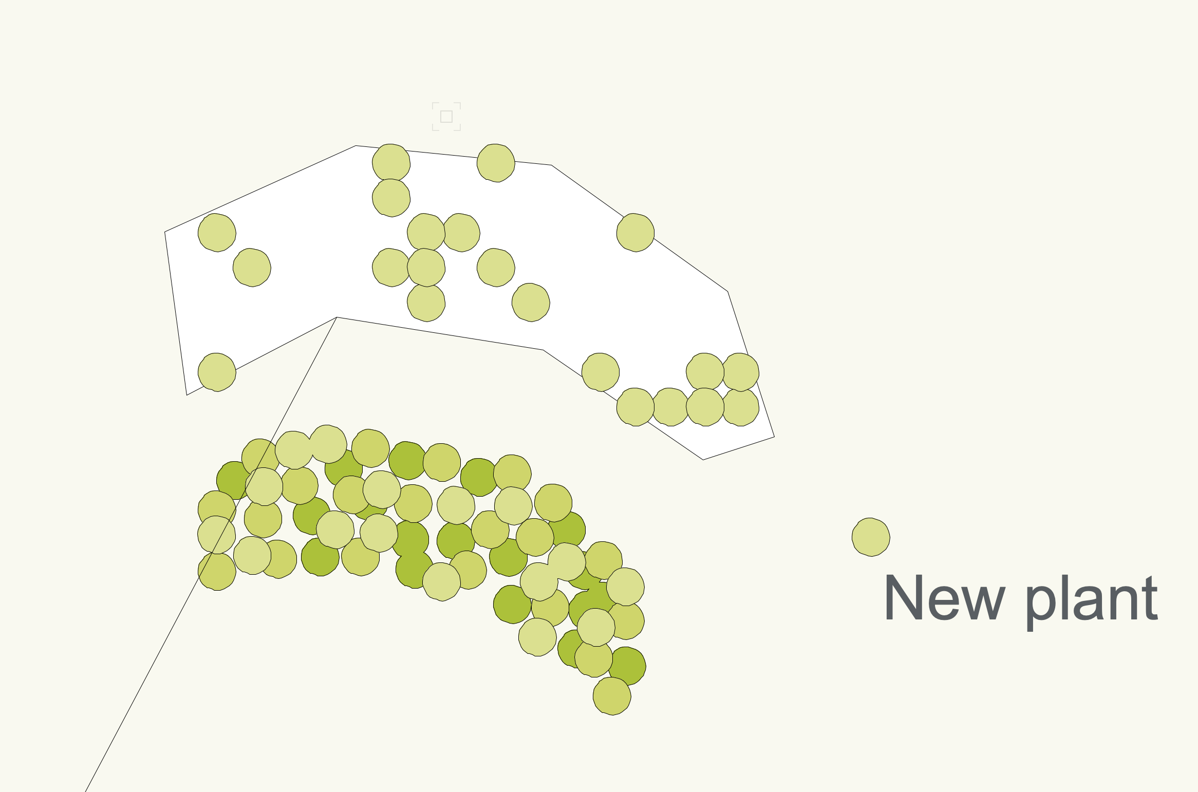
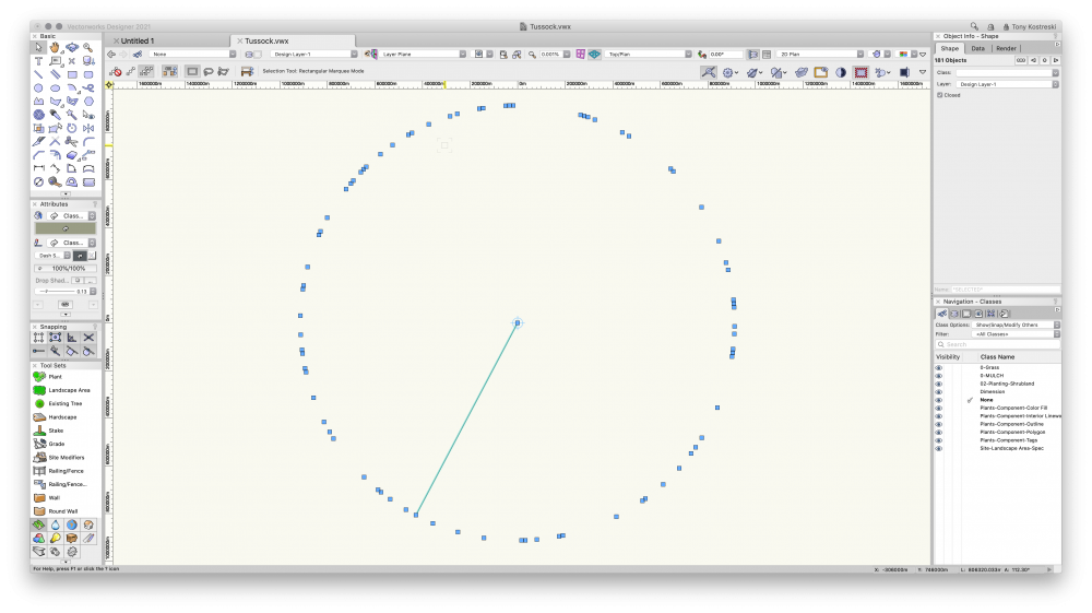
Hey @Steve Riddle , I played around with your file. Can you share how you created a plant style? That seems to be the culprit and if there is an issue, I'd like to submit a bug on this. Your plants are in fact showing up, just thousands and thousands of meters away. I created a new plant and added it to the existing landscape area with no problem. Tussock-tkostreski.vwx

-
@Poot here is your file back if you want to take a look at it. Landscape Area 3D Test.vwx

-
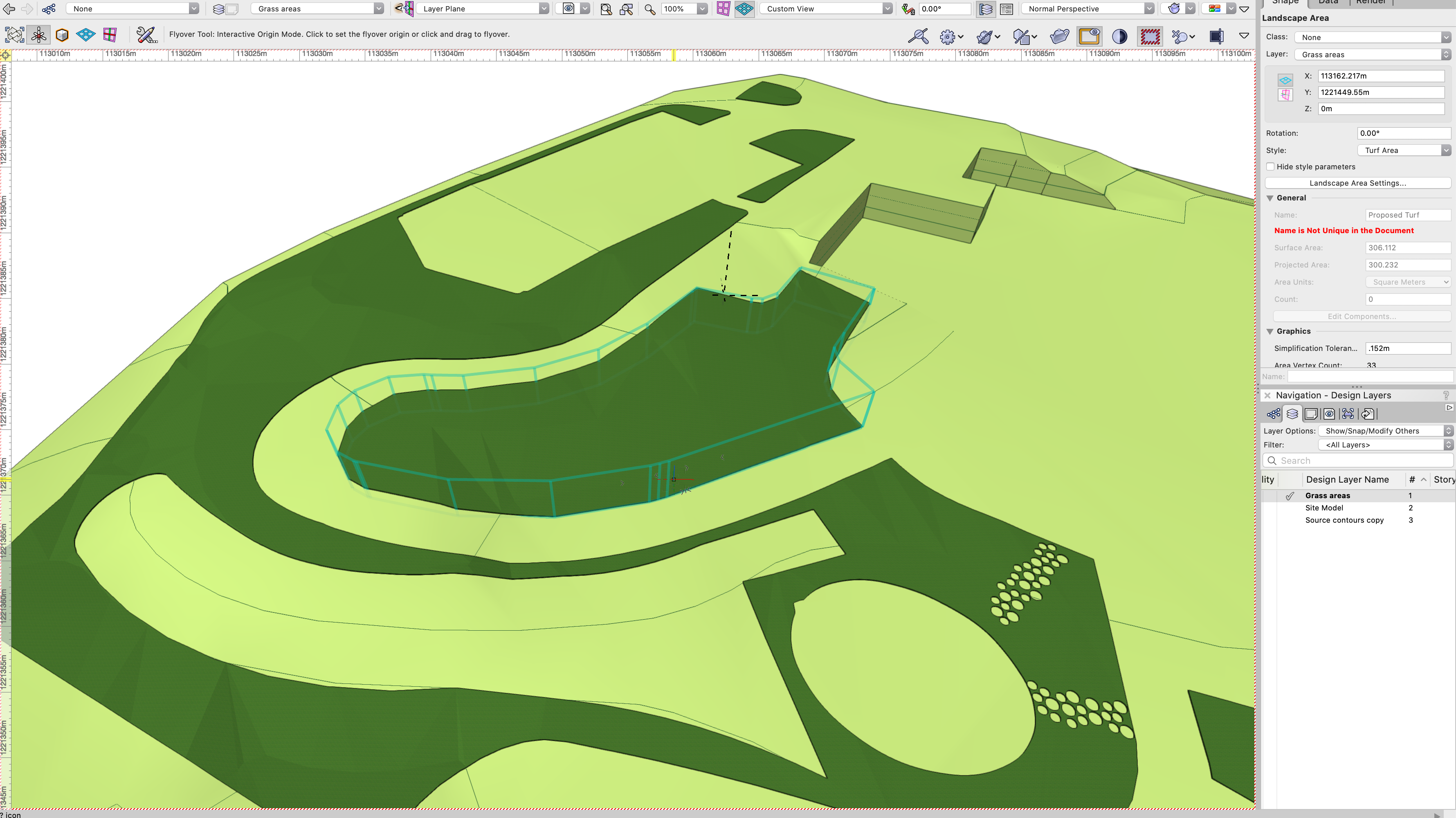
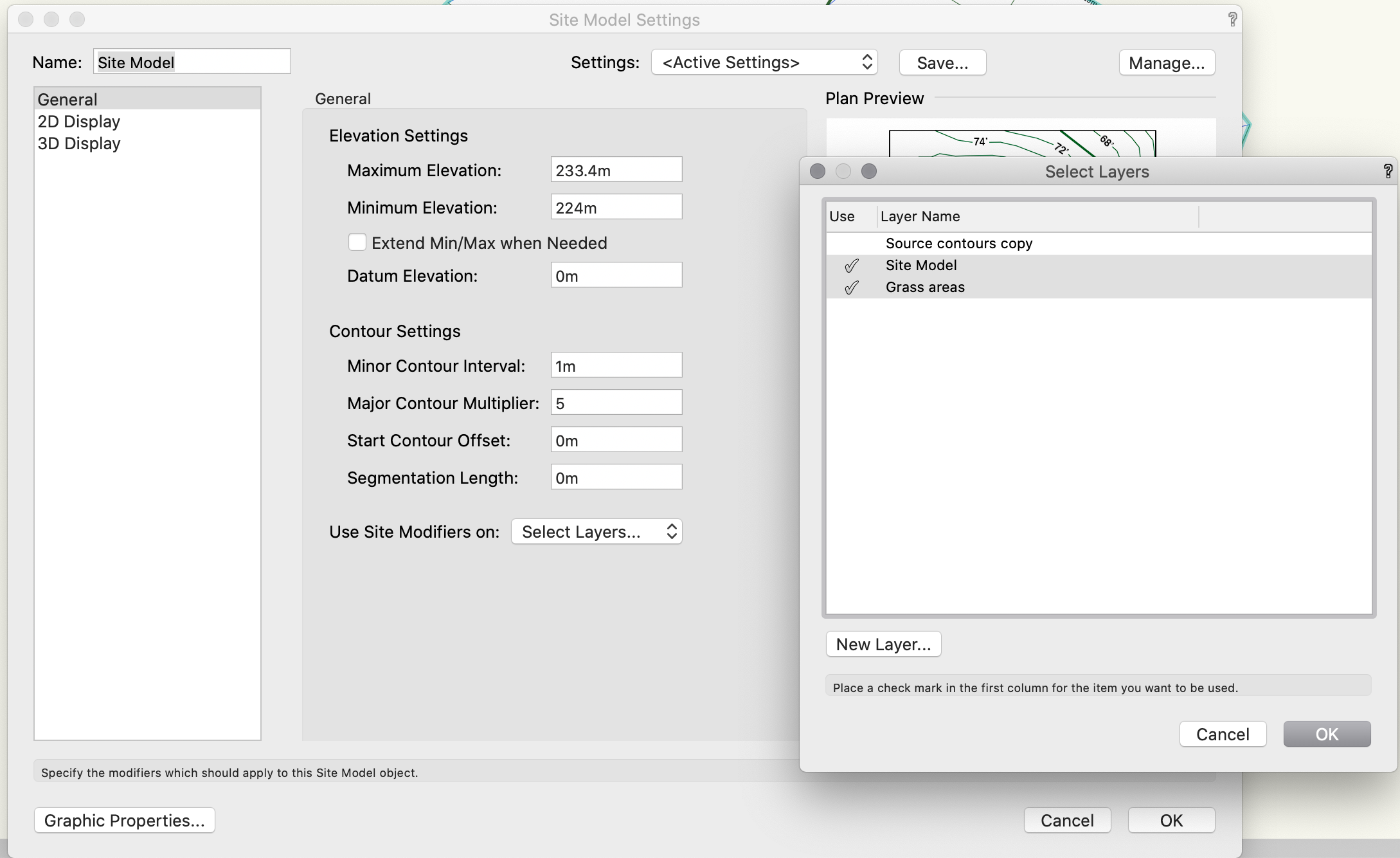
Thanks for sharing the file, @Poot as that helps with determining the issue. I see what the problem is. "Site-DTM-Modifier" class is a special class where geometry that's created on this class will turn it into a site modifier for the proposed site model. This is great when you want to use 3D Polygons, NURBS, and 3D Locus to modify the site model differently than what's possible with other tools (site modifiers, hardscapes, landscape areas). Since your source data on Design Layer "Source Contours copy" is on "DTM-Site-Modifier" class they are acting like a modifier for the proposed site model. In the site model settings you are telling the site model to listen to ALL DESIGN LAYERS. You can either deselect this design layer so the site model does not listen to it or put your source data on any other class than "DTM-Site-Modifier". Hope this helps!

-
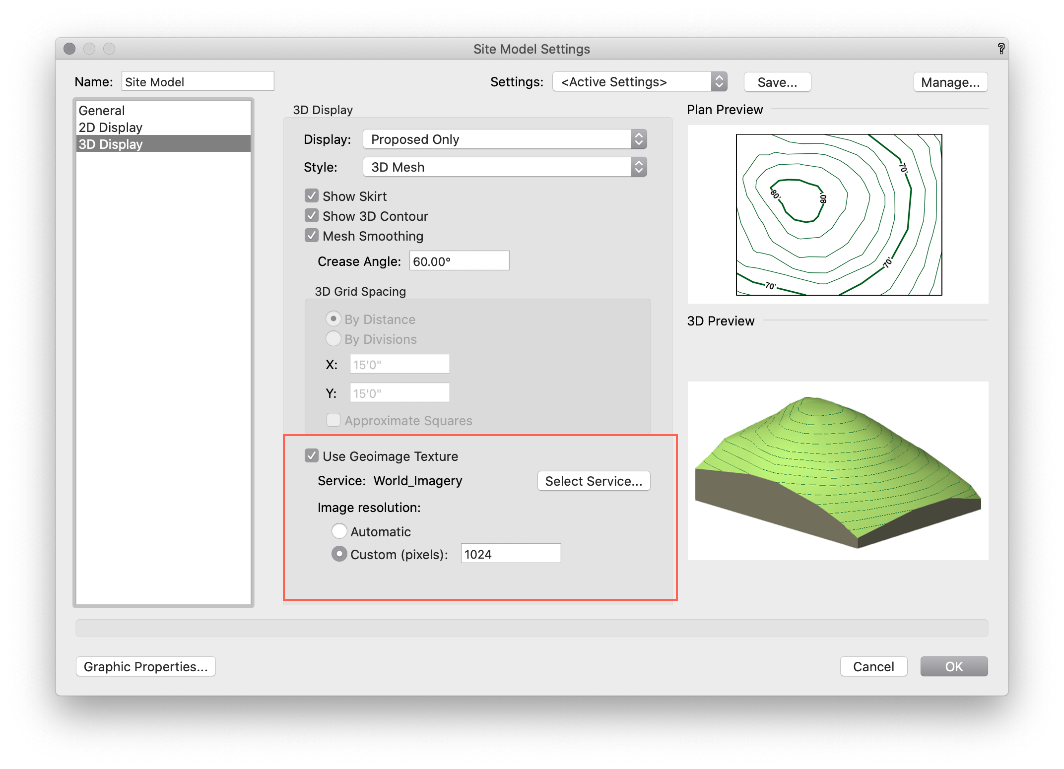
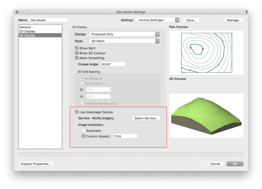
All of your design layers (that relate to each other at least) should be at the same layer scale, otherwise, they simply won't align. Assuming that your file is properly georeferenced & geolocated there is an option within the site model settings to adjust the resolution of the imagery. The number will really depend on the size of the image you're gathering and it's location. My suggestion...place a geoimage and see what resolution works. If it displays with a geoimage it should work with the site model geoimage texture. Hope this helps!
-
@Poot are the landscape areas set to align with the existing site model or proposed?
-
One more tip. These site model settings can be saved, so once you get your preferred representation, Save & Save Time
-
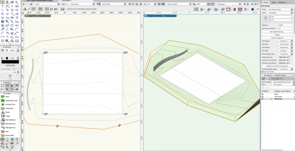
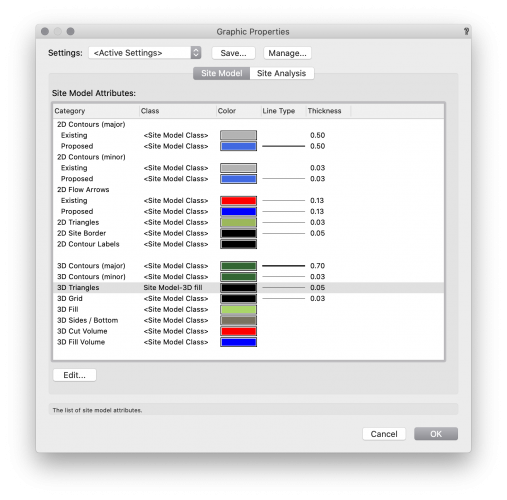
Hi @Rob Norris--welcome to Vectorworks! Attached you'll find a sample file you can investigate. You are right about the Design Layer stacking order...note the stacking order of the design layers in the screenshot below in the Navigation Palette... "Walls" above "Site Model" above "Hardscape". Like that, contours will appear above the hardscape but geometry on the "Walls" design layer will be above the contours on the "site model" layer. In the screenshot above, the site model is selected and the 2d attributes are set not have a fill. Warning though, this will cause the 3d fill to also disappear. Luckily, we have control over this setting in the Site Model Settings>Graphic Properties window—see below. We can specify a new class or simply override these settings. By default, they are set to <Site Model Class>. Apply a fill to "3D triangles", or better yet, set to a new predefined class with a fill. sample site model and hardscape.vwx I hope this helps!
-
Plant Symbols Plan Shadow Visibility Question
Tony Kostreski replied to Phillip Tripp's topic in Site Design
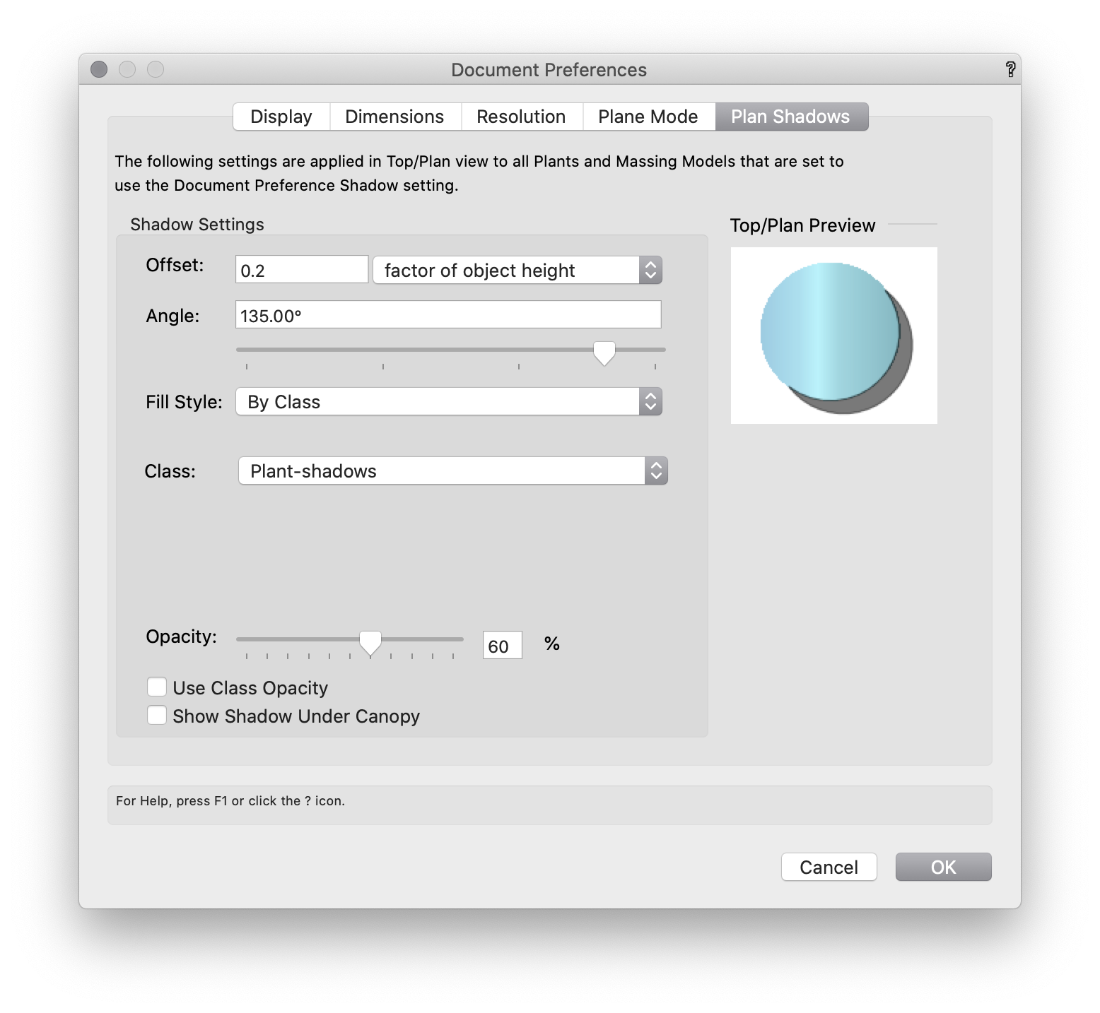
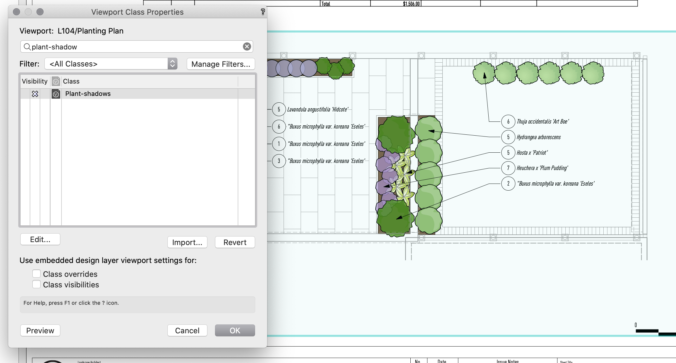
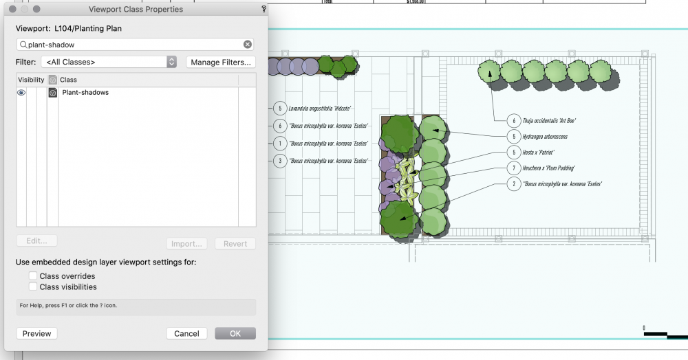
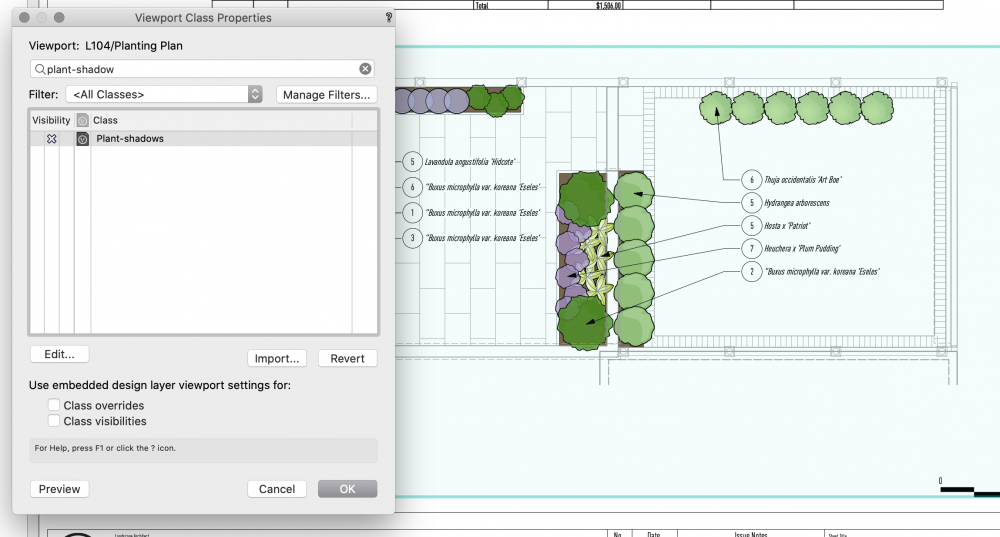
Hmm...Actually you are correct—there appears to be a bug with the class opacity. I'll file the bug but in the meantime, you can control the document settings opacity as you mentioned. The rest of the attributes work fine. For internal reference (VB-177053) -
Plant Symbols Plan Shadow Visibility Question
Tony Kostreski replied to Phillip Tripp's topic in Site Design
Hey Phillip, Yes, in the Document Preferences>Plan Shadow there is an option to set Fill-Style to class. Create a new class (i.e. plant-shadow) and set the attributes. On specific sheets you do not want to display shadows turn the "plant-shadow class" off. I hope this helps and hope you and the team are doing well 🙂 Tony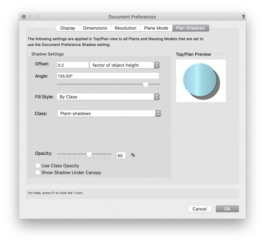
-
Hi @Laura Stone, yes this is a known bug that'll be addressed in 2021 SP3 but for the time being, placing the landscape area on a site model will resolve the issue. Quickest way to create a site model is draw a 2d shape (like a rectangle), and then select "Create Site Model">"Site Model from Boundary".
-
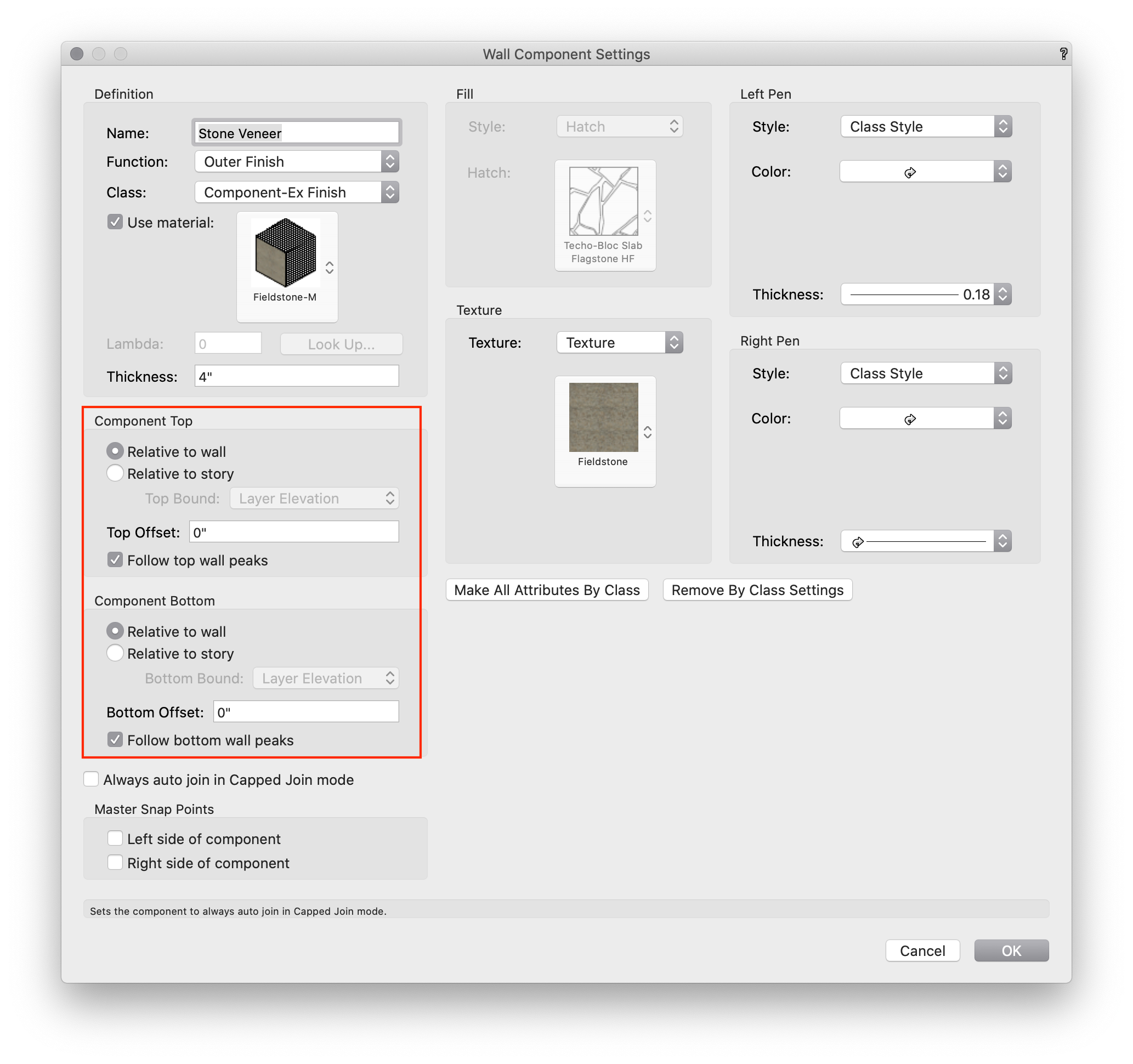
Hey @Landartma Check to see if your component settings have an offset set to it.

-
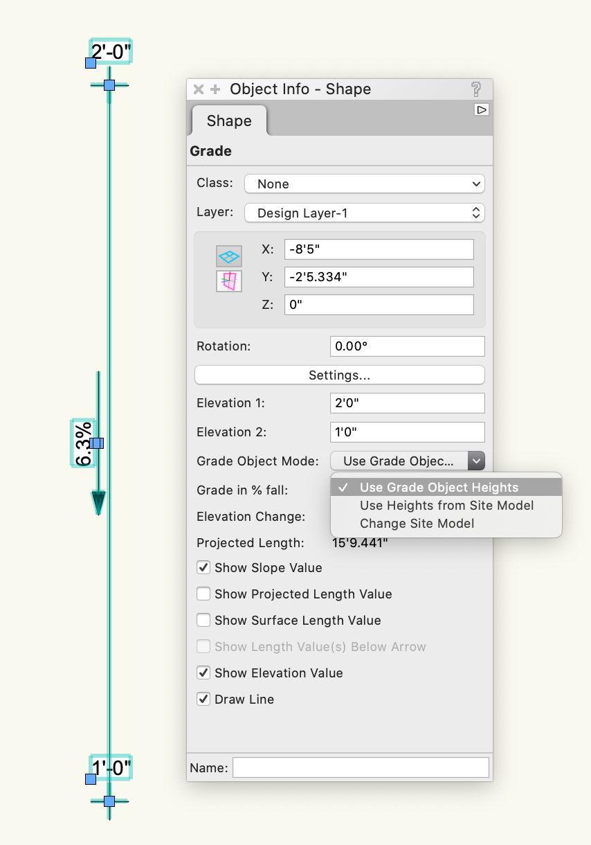
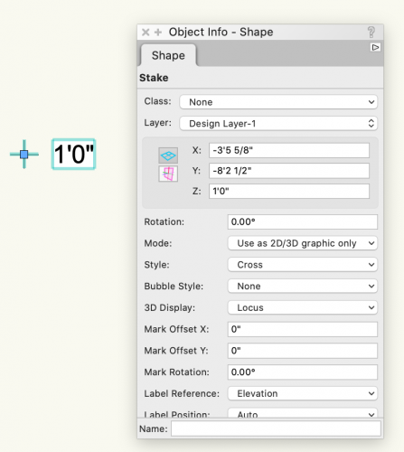
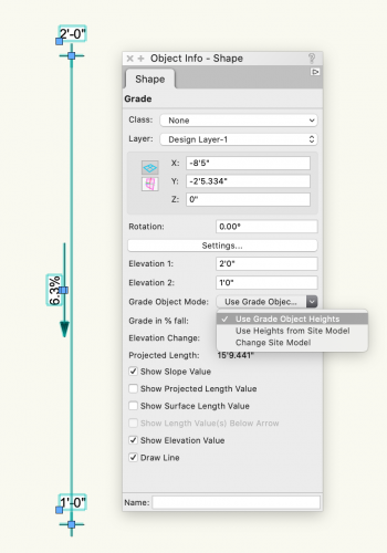
Hey @Landartma -- If all you really need for this project is to show significant spot elevations & slopes, I would suggest using the stake object for individual spot elevations and the grade tool for slopes. Just make sure you are using the appropriate settings. The Stake Object (spot elevation) has a mode for "Use as 2D/3D graphic only" then you can input the height in the "Z" Elevation. The Grade Tool has a mode for "Use Grade Object Heights". Hope this helps! Tony
-
Search function
Tony Kostreski replied to Stefan_b's question in Wishlist - Feature and Content Requests
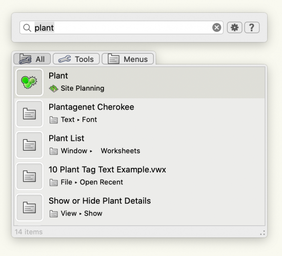
Hi @Stefan_b, Assuming you are in Vectorworks 2021 have you tried using "Quick Search"? By default the shortcut key is "f". Double-check in the Vectorworks Preferences if you have this disabled. You can type any command/tool and it will appear. Also, make use of the "Smart Options Display"...very handy and I believe the default shortcut key is "spacebar". I hope this helps 🙂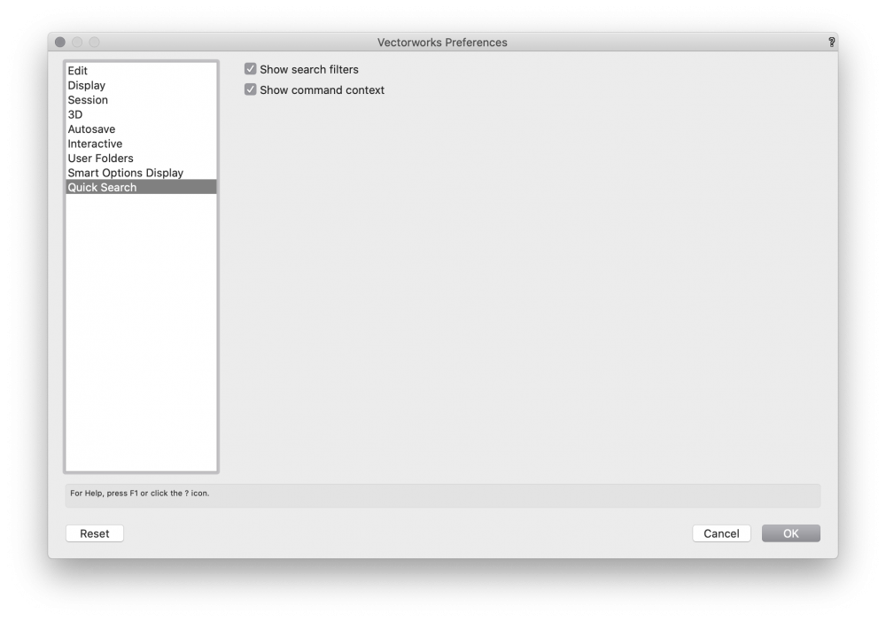
- 1 reply
-
- 4
-

-
Parametric 2D arrows with fill
Tony Kostreski replied to Kaare Baekgaard's question in Wishlist - Feature and Content Requests
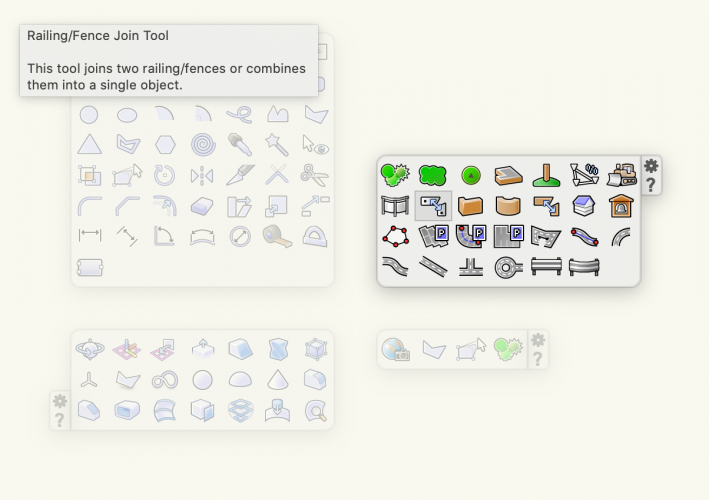
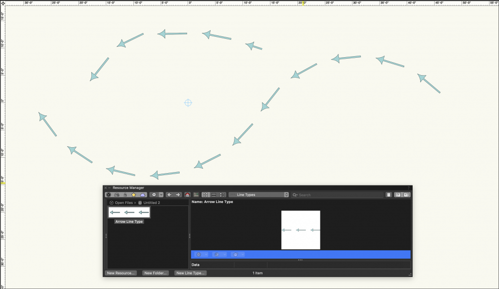
I'm curious if complex linetypes answers this question or are you looking for something different? Complex linetypes allows for complete customization of how the arrow looks and what the gap is between them. They can then be applied to any shape.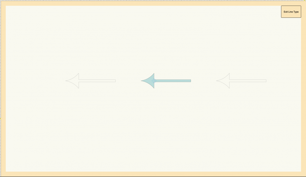
-
@SamB If Tom's suggestion does not suffice regarding the new GIS tool set, Vectorworks can import georeferenced images with associative world files (.bpw, .jgw, .pgw, .tfw, .gfw, or .wld formats). ECW, GeoTIFF, and JP2 (JPEG 2000) files store the georeferenced information with no need for an associative world file. When importing, you just want to make sure your Document Units match that of the photo. For more information check the Vectorworks help https://app-help.vectorworks.net/2021/eng/index.htm#t=VW2021_Guide%2FImport%2FImporting_georeferenced_images.htm For high resolution imagery, I've heard good things about https://www.nearmap.com/us/en
-
Problem with Orientation of North Arrow in a Viewport
Tony Kostreski replied to ashot's topic in General Discussion
Hi @yasin2ray (Anna)--yes. If you have a heliodon on a design layer, the north point in annotations will automatically point in the same direction as the heliodon regardless if the viewport is rotated or not BUT there is presently a bug that's being worked on that prevents this from working when Document>Georeferencing is activated. I will post back here when that's resolved. 🙂 -
Problem with Orientation of North Arrow in a Viewport
Tony Kostreski replied to ashot's topic in General Discussion
Okay...so after further testing I CAN replicate your issue—quite annoying. It definitely has to do with georeferencing. For internal I've added a bug (VB-175609)