AndySmithArch
-
Posts
22 -
Joined
-
Last visited
Content Type
Profiles
Forums
Events
Articles
Marionette
Store
Everything posted by AndySmithArch
-
Often we need to share specific drawings with consultants. Most of them use AutoCAD so a simple File-Export-Export DXF/DGW lets us select the specific sheets we want to share with them. They can then import and manipulate the drawings. We now have a consultant who is also using VectorWorks and we'd like to be able to export 3 specific Sheet Layers from our 75 sheet VWXP file into a single VWX that I can send to them to open and work with. Ideally the viewports on the sheet layers would be able to be manipulated so they'd need to bring in the design layers that feed the viewports. I'm not familiar with AutoCAD but the DWG export (which I can zip up and email/dropbox to them) seems to be able to be imported and snapped-to and moved around easily and it seems that there should be a similar function in VWX whereby the consultants can open the sheet layer for, say, the basement lighting plans and select/copy/delete/move the light fixtures and bring them from my VWX file into their own VWX drawing set for coordination. The File-Publish option only seems to allow publishing to PDF or DWG or DXF - not to VWX. The File-Export-Export to VWX options only seem to allow you to export the entire file (including all design layers, sheet layers, classes, viewports, objects, symbols, etc) and then only export to an older version of VWX. If we're both using VW2023 it seems that there ought to be an option (that I'm perhaps overlooking) for me to export to another VW2023 file and choose which sheet layers I want to send them. Does anyone have any suggestions? Thanks
-
Problems with Publishing: possible bug selecting wrong sheets
AndySmithArch replied to AndySmithArch's question in Troubleshooting
Any ideas? This issue continues to happen. Anyone else ever seen this? -
Problems with Publishing: possible bug selecting wrong sheets
AndySmithArch posted a question in Troubleshooting
I seem to have a strange bug going on. This is in a project file but no-one else who works on this file has this issue. Closing VW and reopening it seems to cure the problem for a while but it eventually comes back. I have tried recreating my working file, without success. See attached video. Issue: Vectorworks won't let me publish the sheets I want to. Symptoms: I click FILE - PUBLISH and the Publish window appears. In the right hand pane, a single sheet is shown from a previous publishing (A1.01 [Site Plan]). Note, I do not have a sheet with this name in the set. The closest I have is A1.01 [Site Plan (House)] so it's possible that the sheet was renamed at some point in the past. I click the double left arrow (<<) to empty the right hand pane. In the left hand pane I have a list of all my sheet layers. I want to publish one of them so I select the sheet I want to publish (A3.11 as an example, but this issue affects all sheets) and click the right arrow (>) to move it to the right pane. Instead of having A3.11 appear in the right hand pane, A4.02 appears in the right hand pane! If I hit publish, sheet A4.02 will be published, not the sheet I need. I check the left hand pane to see if I accidentally selected the wrong sheet but now A3.11 has disappeared from the left hand pane (like it would if you moved it to the right) so I cannot select it to move it to the right pane; A3.11 cannot be seen anywhere anymore. Interestingly, A4.02 still appears in the left hand pane AND the right hand pane. If I select and move A4.02 from the left hand pane at this stage, A4.03 shows up in the right hand pane, below A4.02... So, before hitting publish in the Publish window, I highlight A4.02 and A4.03 in the right hand pane and click the left arrow (<) to send them back to the left hand pane. Now, the left hand pane has TWO copies of A4.02 and A4.03 in it but A3.11 is nowhere to be seen in either pane - it has vanished... So, for fun, I highlight both copies of A4.02 in the left hand pane and move them to the right hand pane. Guess what happens? Wrong! Both copies of A4.02 disappear from the left hand pane but do not appear in the right pane. Instead, the right pane now lists A4.03 and A4.04, both of which continue to be shown in the left hand pane. A4.02, like A3.11 now doesn't appear anywhere. I can keep moving sheets from left to right and back again and thoroughly destroy the list of sheets as it gets tangled up. Observations: This seems to happen regardless of whether I use a project file or a non-shared file. I think I have seen this happen in my other versions of VW (I have projects that use VW2017 all the way to VW2023) but cannot say for sure; I am mostly working on projects in 2020 and 2023 (which I am not yet publishing from). I am running SP6 in VW2020, as are my colleagues. My colleages don't have this issue with the same project file or any other files. Workaround 1: Restart VW cures the problem for a while - hours or days. Workaround 2: If I select ALL of the sheets in the left hand pane and move them to the right hand pane, the sheets I want to publish will be included in that selection and will show up in the right hand pane. I can then select the sheets I don't want to publish and move them back to the left pane leaving me with the sheets I want to publish and I can proceed. However this is NOT convenient when I'm publishing a set of, say 45 sheets that are peppered throughout a drawing file containing, say 100 sheets. Workaround 3: If I don't clear the right hand pane when the Publish window appears, I can add sheets to the right hand pane and it works fine. I can then finally remove the A1.01 Site Plan sheet from the right hand pane, leaving the right hand pane populated with the correct sheets I want to publish. This has been going on for a while now so I'm pretty much resigned to just rebooting everytime it begins to happen, but if there's something I can do to resolve it permanently, I would like to. Cheers. Publishing Bug.mov -
Scenario: I have a model which contains around 30 windows. I used a window style to apply a specific frame profile, frame material, frame finish, etc. When I created the style, I chose for the configuration of the window to be "By Instance". I then applied the style to the windows and it seemed to work OK. It preserved the existing configurations, sash sizes, etc. Now I want to add a comment to one of the User Fields in the data tab of the window settings for all windows. But, if I edit the window style plugin, go to the DATA screen and then enter anything against any of the User Fields, it thinks about it for a few seconds and then alters ALL of the windows in the model to have a different operation whereby the left sash is now a casement and the right sash is now fixed, even if previously both sashes had been fixed or both had been casements, etc. How can I update the plugin to add notes to the windows, without it automatically changing other undesirable aspects of the windows? It's like I want to be able to update the plugin style but then choose which specific fields I want to push out to the windows that use that style so that it doesn't overwrite the elements of the windows that are unique to each unit. Thanks!
-
Vectorworks 2023 Graphic Legend Annotation Issue
AndySmithArch replied to AndySmithArch's question in Troubleshooting
Any further progress on this? I really need to get these schedules finished off but am still not clear whether I'm doing something wrong or whether the Graphic Legend tool is just broken. -
Vectorworks 2023 Graphic Legend Annotation Issue
AndySmithArch replied to AndySmithArch's question in Troubleshooting
Hi Pat, I’m not sure I follow: there are only door objects in the Graphic Legend in this example. I DO have a separate Graphic Legend on a different sheet layer for my window schedule but that’s a totally different legend and is configured to pull window objects whereas this one pulls doors. It too has the same issues but these are not combined door/window schedule/legends. You can see this in the Source Criteria field at the top of the screenshot in my last post - it’s only pulling in doors. Why does MY picklist in my screenshot relating to the auto dimensions for this door schedule have different options to yours? This is pretty frustrating - VW is clearly intended to be used to add annotations to Graphic Legends; it’s one of the options that pops up when you double click the legend. But why is it arbitrarily blowing up the size of the cell? Why are we forced to add annotations on a per-cell basis when it’s equally likely that we would want to add annotations across all cells in one step? Why are my auto dimension options different to yours? How can I add a single line across the bottom of all the doors in my Graphic Legend to represent the floor elevation? Thanks, Andy -
Vectorworks 2023 Graphic Legend Annotation Issue
AndySmithArch replied to AndySmithArch's question in Troubleshooting
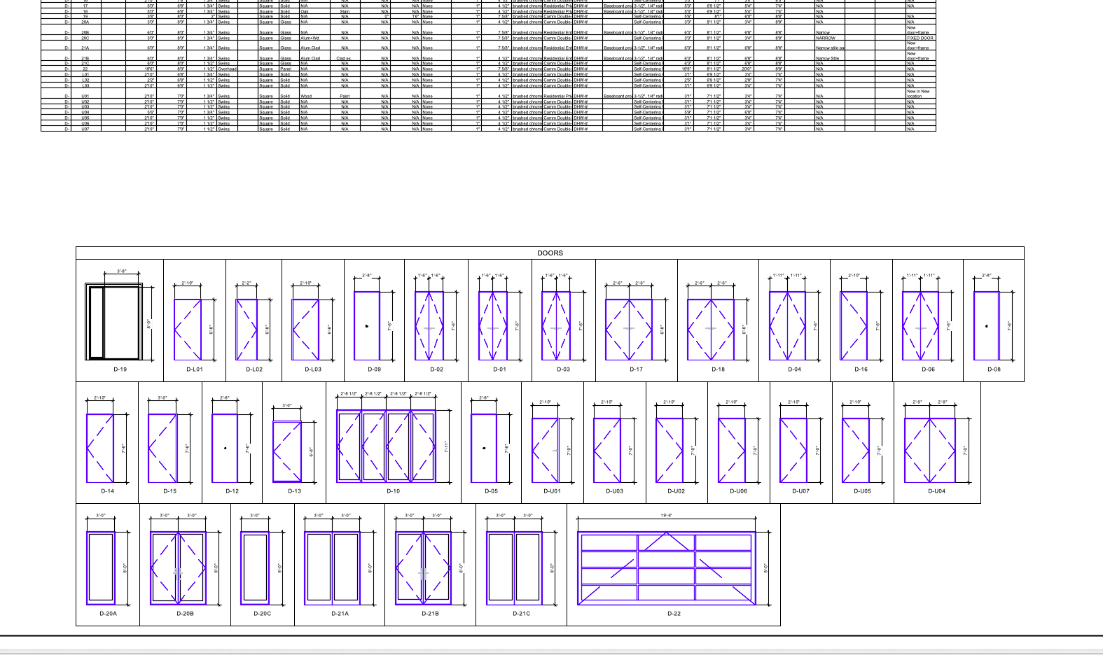
Thanks Pat but I'd seen that thread already. Problem is that I don't have those same options - possibly because this is a door object rather than a window? See attached. I need it to show the leaf height (not the unit height or RO height) and want to see a number of horizontal lines: 1. A solid 0.5 line to denote the floor across all doors (some of the doors, such as access doors for crawl spaces might have their sill 3' above the floor but should still show a line denoting the floor, below them.) 2. A dashed line at 3' above the floor, denoting the height for a peephole/view hole. 3. A dashed line at 3'-11" above the floor denoting the maximum height permitted for handles to be installed at. 4. A dashed line at 5' above the floor, denoting the height for a second peephole/view hole. I will also want to add specific annotations for certain doors where they have unique features that need to be shown. These are all things we would normally add to building elevations in an annotation layer. Thanks, Andy
-
When I try to add anything to the annotation layer of a Graphic Legend on a Sheet Layer, instead of simply showing the object that I drew, on top of the Graphic Legend, where I placed it, Vectorworks arbitrarily messes up the cell spacing and layout of the Legend. The attachments show my Legend before I try to add a floor line to the annotation layer. The second attachment shows me drawing the line in the annotation layer. In a regular Viewport annotation, this line would simply lay on top of the viewport where I drew it. However, with the Graphic Legend, the line doesn't simply stay put where I placed it; the third attachment shows how VW bizarrely blows up the layout of the legend. If I try to add 3 lines; one for each floor line under the door sills, it's even worse. Also, in addition to completely screwing up the size/layout of the cells just by trying to overlay a line onto my schedule, it seems to assign the annotations to specific cells: So how can we put an annotation over the whole legend, rather than on specific cells? I'm trying to achieve something like I've shown in the 4th attachment where I show the floor line, hardware heights, etc over each door and each row. Not being able to place a Graphic Legend on a design layer (where we could then use a viewport to show it on a sheet layer and annotate it normally), makes this harder. Thanks, Andy


-
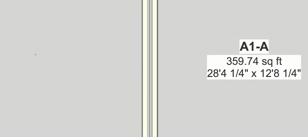
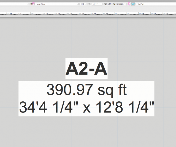
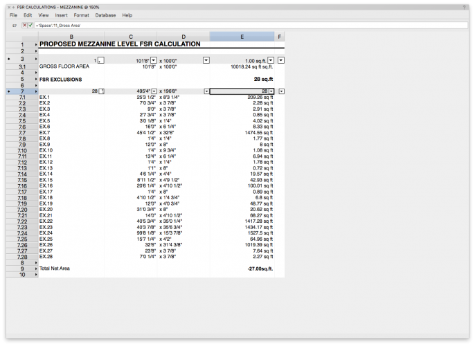
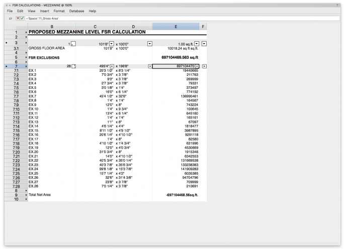
Hi there, I know I'm running SP0 (the updater keeps throwing an "unknown error has occurred" message so I'm giving up updating it for now) but, I'm hopeful that my problem is caused by my own stupidity rather than a bug in SP0 of VW2019. Please see attached screenshot. I'm trying to use the space tool to create a summed value of a selection of space objects from a single design layer in my file - about as straightforward a task as it gets... I've copied the syntax and cell details from another file from a colleague and their file is working perfectly. However, the "Net Area Number" column in my file/worksheet is bananas. Any ideas why it's turning a space measuring approx 3sqft (EX.3) into just under two hundred and seventy thousand square feet in column E? If I change it to be Gross Area then column E looks more reasonable (although I don't know why it would have a problem with Net Area Number if it's working in my colleague's file) but cell E7 then just changes to "28" which is obviously just a count of the number of space objects, and column E5 doesn't give me a sum total of the areas combined; it just says 28 sq.ft which is obviously just the count again. Thanks for any pointers as to what I've done wrong. Andy
-
Linear Materials Flipping (VW2017)
AndySmithArch replied to AndySmithArch's question in Troubleshooting
That's right - I'm either drawing details in 2D or creating a section viewport that I'm drawing on top of. Either way, it seems that the linear material tool makes seemingly arbitrary decisions about which side it believes is the outside of the material. For some unspecified reason it seems to randomly flip the instance of the material back and forth as you reshape it - I have no idea what logic it uses to drive that decision. Also, when it DOES flip, it doesn't flip around its centre-line - it flips along one edge. So you can find your line of drywall suddenly intersecting with the framing you're trying to put it against. Any other folks finding a similar issue or is it just Taproot and me who are experiencing this? -
Linear Materials Flipping (VW2017)
AndySmithArch replied to AndySmithArch's question in Troubleshooting
Is anyone else experiencing this - or just me? Any ideas? -
Does anyone know why my linear materials keep flipping when I resize them or edit them? And how do I prevent this happening. Example, I use the linear material tool to draw a section cut through a layer of 5/8" drywall which is on the underside of a stair stringer and landings. So the material runs horizontally along the underside of the lower landing, then turns 30° to run up under the risers before turning -30° back to horizontal. I find that my drywall linear material shows the finished surface on the wrong side and I cannot seem to choose to flip it. On the rare occasion where it seems to work ok, if I need to use the reshape tool, it seems to behave unpredictably and can randomly flip my finished surface from top to bottom or bottom to top. Another example would be drawing Corrugated Deck W Fill. If I want to draw a curved line of the material to represent drainage mat running over a perimeter drain, I find that I cannot control which face the corrugations appear on. And if I add a curve to the run of material, VW seems to decide for me that I must want to flip the material upside down and does not let me choose whether side A or B is the corrugated side. Thanks, Andy
-
VW2017 - Section Viewport. Wall Hatch Scale
AndySmithArch replied to AndySmithArch's question in Troubleshooting
Hmm... I solved my own issue. I unchecked then rechecked the "Show Wall, Slab and Roof components" option from the Advanced Properties area of the Section Viewport OIP. I have no idea what caused this issue but that seemed to cure it. Cheers! -
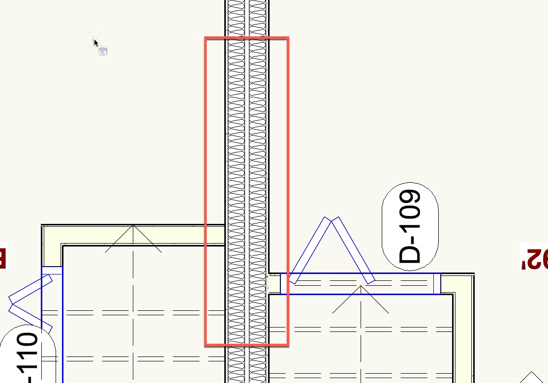
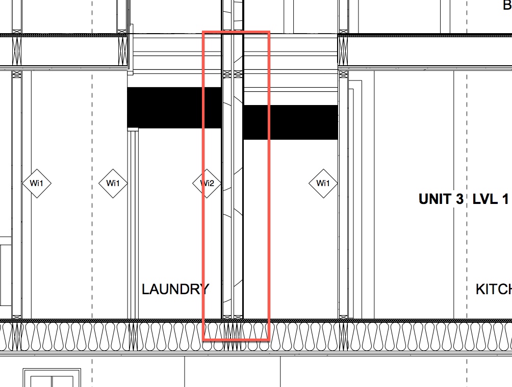
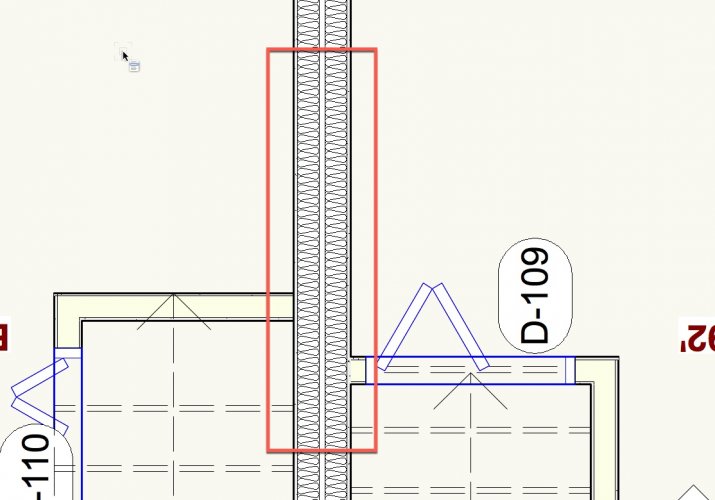
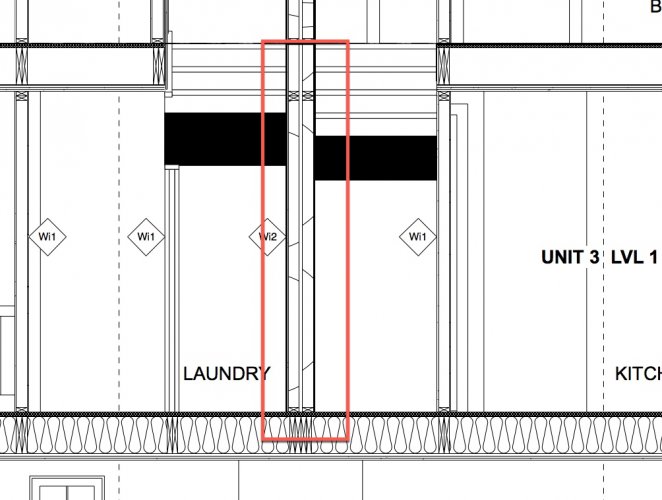
Hi folks, I have been working in a section viewport for a project I'm assigned to and (I believe, without me doing anything) my wall fill hatch on a party wall (and several other walls) seems to have gone haywire. It looks like the scale for the fill has changed so I'm now seeing a super-sized version of the hatch. Everything looks fine when I switch to plan view but the section party wall insulation fill is all wrong. Is there a setting somewhere I've hit by mistake? Thanks! Section View: Plan View:
-
I have created a file in 2018 which uses our company title block. I have exported the file to a VW2017 file so that my boss can continue to work on the file in 2017, now that I've finished my tasks. However, when he tries to edit the title block (which I could edit fine in 2018), he gets a message saying "The selected object has no edit behavior". VW2017 recognizes the object as a "Title Block Border", like it does for me in VW2018, so why would he not be able to edit it? If I open the VW2017 file in VW2018, once it has opened and converted the file to VW2018, I can edit the title block fine again. Presumably one of the purposes of exporting to VW2017 from 2018 is to ensure that VW2017 is able to manipulate the file, including the title block? I've noticed too that if I create a brand new document in VW2018 using our template, the title block is now referred to as a "Sheet Border" rather than a Title Block Border. This appears to export file to VW2017 so why would this one file have somehow changed itself to a Title Block Border and become locked when exporting to VW2017? Thanks!
-
Dragging up an old, neglected thread but I'm looking for a similar function. Lots of Windows on a wall, ID tags all over the place. I'd like to move them all to snap them to a single line which doesn't conflict with other annotations on my sheet layers.
-
Thanks markdd The problem I'm having is that 99% of the dimensions in the drawings need to be in fractional inches, apart from the elevation markers which need to be in decimal. Thanks,
-
Hi everyone, I'm working in an imperial unit file but from a metric survey (Canada...) The survey has given me elevation markers in decimal metres. 72.68m for example. But I'm needing to show my elevation markers in imperial. My file is set to imperial units so it's easy for me to set the Z value of an elevation marker to 70.63m and see it show up as 231'8-3/4" but I really need it to be in decimal feet - so something like 231.78' Does anyone know if this can be done? Thanks!
-
Thanks guys, Neil, you have actually been helping me with this issue directly since I originally posted this thread. I'll do some research into the referencing approach but colleagues have advised me to stay clear of it if you're referring to the situation whereby you have multiple VW files which are referenced in a master file. If you're talking about a situation where you're only referencing assets on different layers within a single file, that sounds different. However, although one of my applications was to use these symbols to create modular units to stack into a building, I should point out that: 1. All I was trying to do was to repeat a symbol multiple times - I had no intention of changing its scale or making unique changes to these symbols. I just wanted to create a self-contained living unit as a symbol and then replicate it 10 times in a floor plan. This would mean that if I wanted to move a window, I would do it once in the symbol and see it replicated throughout the building. I am not certain why this should be difficult for VW to achieve. 2. I also have this same text scaling issue on 2D symbols that have nothing to do with walls, space objects, etc. For example, I created a 2D symbol comprised of elevation markers and dimension markers. This 2D symbol would be dropped onto a number of viewports to show grade and floor elevations in sections and elevation drawings. If I want to change one of these elevation markers (say if we decide to lower the roof), I should be able to edit the 2D symbol, change one of the dimension markers and then drag the elevation marker to snap to it. However, when I do this, the black and white circle of the elevation marker immediately shrinks to a tiny size but the text remains the 'correct' size. So we're not actually talking about text scaling specifically but seemingly random scale hiccups of certain items when a symbol (or part of a symbol) is scaled or moved. See this video for a demonstration. I would love to know why this is happening and how to prevent it - I'm sure I'm just doing something wrong. Thanks! SCALING_ISSUE.mp4
-
Any thoughts?
-
P.S. Should have said - this is with VW2017 Architect edition. SP4. Build 373796
-
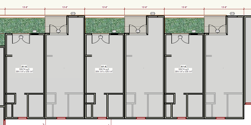
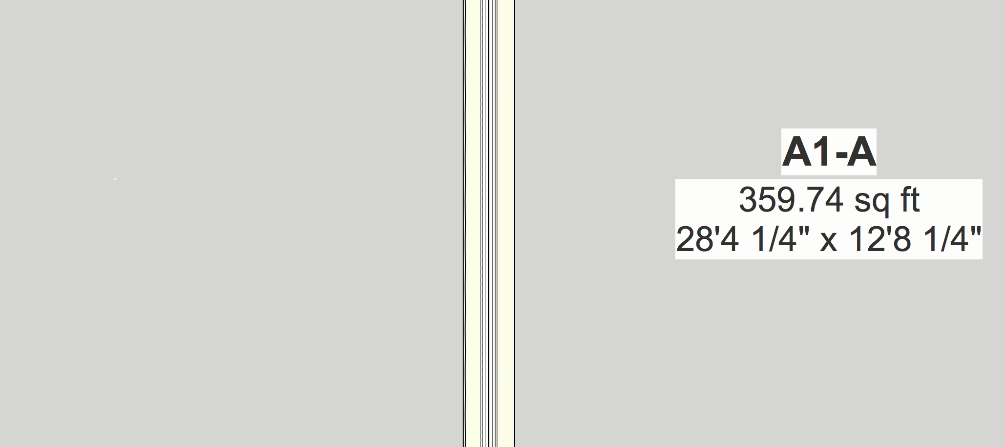
Hi all. I think I'm missing something obvious. I can create a symbol from a group but when I insert it back into the same drawing in which it was originally created (even the same design layer that it was created from), I'm finding that my text scale changes. For example, a simple square room with a SPACE tool showing the floor area. I build the room using walls, slab, etc and place the space tool on it. The text appears fine and is automatically set at - I believe - Arial 14pt and 12pt. No problem so far. Then I convert the items into a group and then convert the group into a Symbol (World-based or Page-based scale doesn't affect this issue). The symbol shows up in the Resource Browser. I add an instance of the symbol to the drawing. I can see the space tool is there (because of its fill colour) but I cannot see the Arial 14/12pt text showing the area. If I zoom in to around 10000% I see that the text is still there but is tiny. It appears to have scaled to real world scale, despite me being on a 1/4" = 1' design layer. Has anyone else experienced this? Any advice on how to prevent this happening? Ideally the text would remain at the size it was when I created it (14/12pt) but it's definitely not - I can tell because I have other 12pt text boxes on the same design layer which I can read clearly at a zoom level of 40% Screenshots show 2 symbols alternating. One of them shows the 'correct' size font. The other (with the balcony) shows apparently no text. Other screenshots show that the text actually IS still there but very small. Final screenshot shows the need to zoom into 24000%+ to read the text that should be much larger. Thanks for any help!