


Grzegorz Krzemien
-
Posts
91 -
Joined
-
Last visited
Content Type
Profiles
Forums
Events
Articles
Marionette
Store
Everything posted by Grzegorz Krzemien
-
Help with understanding List on creating a Truncated Cone
Grzegorz Krzemien replied to Todd Drucker's topic in Marionette
@Todd Drucker I'm not sure what you had in mind, but maybe this will help. You can play around my network on "Design Layer-2". If you have any questions about the network just ask. Have fun, Grzegorz COLUMN PRACTICE 2 GK.vwx -
@m.graf, thanks for your help. Could you tell me, why the "Pass" node is needed?
-
Hi all! Is it possible to receive data from Marionette Object to create schedules? I created an object - table and tried to build a simple schedule. It works as unwrapped script, every time I press Run Network new object is generated and it is scheduled as planned. If I convert the network to Marionette Object, records are created, but no data(info) are generated and schedule remains empty. Any hints how to schedule Marionette Objects? File with my script as an example. RecordsAndMarionetteObjects.vwx
-
3D Triangulated structure - Using Symbols?
Grzegorz Krzemien replied to RyanMartinDesign's topic in Architecture
@Marissa Farrell Thanks for this. Could you tell me, if your node is able to work on a list of 3D points? E.g. I have a NURBS surface divided into list of points and I want to rebuild it with your node. I've done an approach, but it fails... It looks like much bigger math skills are needed than they teach on Architecture faculty🙂 mesh 3Dsurface.vwx -
3D Triangulated structure - Using Symbols?
Grzegorz Krzemien replied to RyanMartinDesign's topic in Architecture
Hi. After some research I found something like this. The node that @Marissa Farrell wrote, works on a grid of points in 2D. Maybe she will be able to help. Tried this node on 3D surface, but it does not work. Still working on it. -
3D Triangulated structure - Using Symbols?
Grzegorz Krzemien replied to RyanMartinDesign's topic in Architecture
@Pat Stanford, @roverton18 I don't think it is so simple as it looks like. This kind of things are on my personal list of "things able to do in Rhino/Grasshopper/Kangaroo/ but not so easy in Marionette". :) roverton18 wants to convert any surface into triangular one built from equilateral triangles. Mesh converts surface into any triangles that fits - surface may be built from set of different triangles. So a challenge is not to convert surface into mesh/triangle surface, but to rebuild a surface using base shape (in this case fixed, equilateral triangle). And I have no idea how to do this in Marionette, yet :) But I can give it a try now. I'll do some research and share, if I find any solution. -
Thanks for tips.
-
@mng1986 Try this one. One table is yours, works fine for me. Second table is with "fixed" leg texture. You can not change leg texture without editing script. Bonus: Made new "Real" node. The work like this: in OIP define "min" and "max" value. If "real" value extends min/max value it changes to min/max value. E.g. real = 150, min = 20, max = 100 if you run the node it will generate 100 (real value is bigger than max, so it sets real to 100) real = 5, min = 20, max = 100 if you run the node it will generate 20 (real value is smaller than min, so it sets real to 20) real = 50, min = 20, max = 100 if you run the node it will generate 50 (real value is between min (20) and max (100), so it remains the same) Hope this is what you had in mind. ParametricTable_GK.vwx
-
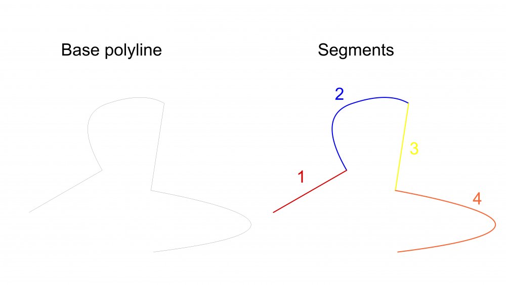
Hello there! Is there any node (or easy way) that returns segments (parts) of polyline from polyline? I mean the situation where a polyline is constructed as a mix of straight segments and arcs. Picture as an example. I know I can get Edges from "Get 2D Edge" node, but this returns only start-end points, not the actual segment and it fails with arcs.
-
@mng1986 Could you upload a file? It would be much easier to check some things. Answers: 1. As I know you can't set min/max values directly. What you can do is a) change/build from scratch new REAL node and add min/max values into the script. b) add set of nodes that check if given value is different than desired. E.g. VALUE connect to CONDITION (greater than), if no run script, if yes - ALERT DIALOG that activates info about wrong value. 2. Could you set a file to check this. 3. I think yes. Try to remove node's Name. E.g. for "Get Texture" node delete "Name" (LegsTexture) in OIP. Then it would not appear in OIP of Marionette Object.
-
Found a little bug inside my Force node. Uploading fixed version. GravityNodeV2.1.vwx
- 1 reply
-
- 1
-

-
Multiple geometry as input into network.
Grzegorz Krzemien replied to Grzegorz Krzemien's topic in Marionette
@Marissa Farrell I've posted second topic about my new version of Gravity Node where my problem occurs. In my file on layer 002 there are two sets of points. I wanted to make each set of points as an single input that I later connect to my Force source node. GravityNodeV2.0.vwx -
Hello there! I had some free time during Christmas and decided to make some upgrades to my Gravity Node I had posted some time ago. New solution is in fact pair of nodes: 1. Force source - node collects all information about how we want to affect our grid. Inputs are: set of points as sources (list of 3D points), force value (real), gravity factor (any number from 0 as an multiplier for force, the more the bigger affect, pop-up menu to decide if force should be positive (push from), or negative (pull toward). 2. Force - node that collects any number of force fields and list of points to modify. There are two examples In my file of how it works: 1 - layer 001, where there are 2 points affecting the grid 2 - layer 002, where there are two sets of points (2 positives and 3 negatives wit different force values) that modify the grid at the same time. Enjoy! GravityNodeV2.0.vwx
-
Hi all! Is there a way to import multiple geometry into network in the same way, as it works for Control Geometry node? E.g. there are 3D points created by hand (as loci). I want to use them as starting points for geometry generated by network, but at the same time I want to keep the ability to relocate them (just like control geometry works but for multiple objects). Tried to use polygon as an input and read its corners as desired 3D points, but this method fails, if there is a need to use two or more sets of points. Thanks for any help!
-
Planar boolean creates additional, unexpected objects
Grzegorz Krzemien replied to Grzegorz Krzemien's topic in Marionette
@m.graf, thanks, it's working now. I had the same idea, but still, "remove duplicates" does not fix the "Planar Boolean Node". If you connect the output of Planar Boolean Node to e.g. Print Debug you will see that it produces enormous number of information. I wanted to know why 🙂 -
Planar boolean creates additional, unexpected objects
Grzegorz Krzemien posted a topic in Marionette
Hi all! I need some help with planar boolean node. My network should be working like this: 1. Insert any planar shape. 2. According to a bounding box of the inserted shape create network of rectangles. 3. Intersect rectangles according to the inserted shape. Somehow planar boolean creates a lot of additional, invisible objects that shows up after further operations of the network. Any hints? Grzegorz TileCounter.vwx -
Hi, all! I wanted to work through a contour node and found something that bothers me. If the input object is a solid with a hole in it, the contour node creates multiple objects ( a general contour and a hole contour). In my example on layer 001 there is an solid, that works fine. On layer 002 there is a solid with a hole and contour node doubles sections. Is it possible to manage output of contour node to create clean sections (if there is a hole it should be included as one object or group?) as intuition suggests? Contour.vwx
-
@mjm Not in this form. Node I made was designed as intuitive tool for fun, not as a mathematical one. Inputs does not represents real strengths. But it might be an interesting challenge to make something like you asked. I will give it a try in my free time.
-
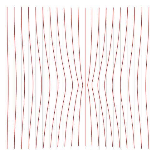
Hi, all. I had been inspired by the "Create and Rotate a line in polar coordinates" topic, and came up with a idea of creating node that mimics gravity. And that's the result, as a simple Marionette Object. How it works: 1. Input point as "Gravity center". 2. Input list of points to modify. 3. Gravity value. Defines "strength" of gravity force. 0 = nothing happens, 1 = point will be moved to the gravity center. Positive values moves points away from gravity center, negative towards it. 4. Radius value. Defines the area where points will be modified. Points outside this area will remain unmodified. Works as a remap of min and max values of radius and transforms it into 0-1 factor, that multiply gravity value. Gives an effect of different gravity strength depends on distance from gravity center. The further the point is, the less gravity will affect it. Hope you will enjoy it. GravityNode.vwx
-
@Benson Shaw, Hi. Try editing Rotate Line node. There's "-" in a front of "rot" in vs.HRotate definition indicating clockwise rotation. Change: #script vs.HRotate(line, p, -rot) For: #script vs.HRotate(line, p, rot) In 2019 works.
-
Perpendicularly placed shapes on curve
Grzegorz Krzemien replied to Grzegorz Krzemien's topic in Marionette
@Alan Woodwell Thanks for your help 🙂 it's all working now. The solution was pretty easy, can't believe I missed it earlier. The problem was, as you noticed before, that vTan is not vAng. I thought that every vector is considered as vector. Rotate node's description says vAng - "It could be a 2D/3D rotation vector...", but I didn't realize there are different kind of vectors in Marionette. 🙂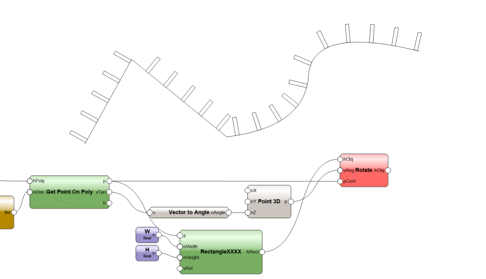
-
Perpendicularly placed shapes on curve
Grzegorz Krzemien replied to Grzegorz Krzemien's topic in Marionette
@Alan Woodwell I need to take a closer look on how it works. This looks promising. -
Perpendicularly placed shapes on curve
Grzegorz Krzemien replied to Grzegorz Krzemien's topic in Marionette
@Alan Woodwell, thank you so much for your time. Unfortunately, connecting vTan in "Get Point On Poly" to vRot in "RectangleXXXX" does not work. I mean they are rotated in the right direction, but at the same time moved from the curve (see picture). I don't understand why this happens, so I tried to use rotate node to make same effect in two steps. I will search for kind of translator between 3DVector and angle, maybe this will help.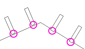
-
Hello there! Tried to create a network that places shapes on input Curve. Shapes have to be perpendicular (placed along curve's normal vector). But somehow I can't see any result. Debugging shows, that last node (Rotate) generate geometry, but it does not show up on screen. Any ideas? Offtopic Is there any progress in finding normal vector to 3D curve/NURBS curve? ShapesOnCurve.vwx
-
It is not important at all. What do you mean by saving as "intelligent symbol"?


