Grzegorz Krzemien
-
Posts
91 -
Joined
-
Last visited
Content Type
Profiles
Forums
Events
Articles
Marionette
Store
Everything posted by Grzegorz Krzemien
-
Slab drainage - how to change slopes values.
Grzegorz Krzemien replied to Grzegorz Krzemien's topic in Architecture
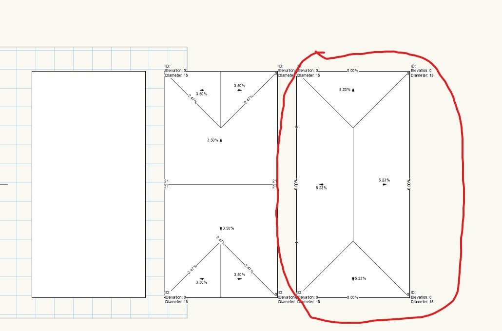
@Tom W., here is a VW2020 file. There is a section that explains, what I want to achieve. I do not think that I can get the same looking section by using Roof tool. Drainage tool v2020.vwx -
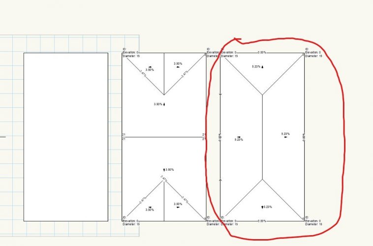
Hello! I have a problem with drainage tool. I wanted to create 4 slopes on my slab that all of them go down toward different edge . I tried to create that by using 4 drains and connecting them. But every time I create this I can not change the slope's value (it's always around 5%). Is my approach wrong? If so, then how can I make this kind of roof? My file and picture of what I'm trying to create are attached. Drainage tool.vwx
-
@Tom W. Yes, that is exactly what I am looking for! Thanks, I can not believe I missed that.
-
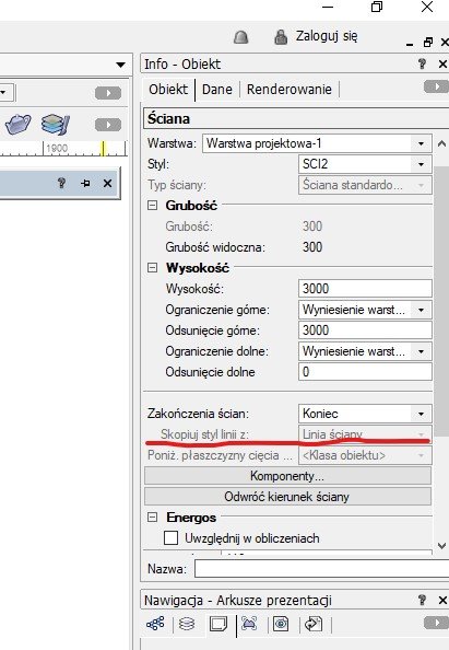
@Jonathan Pickup Thanks, but it is rather work-around. In the Info Palette there is an options but it is greyed "Copy linestyle from..." and it is set to "Wall line". Is it possible to change this setting?

-
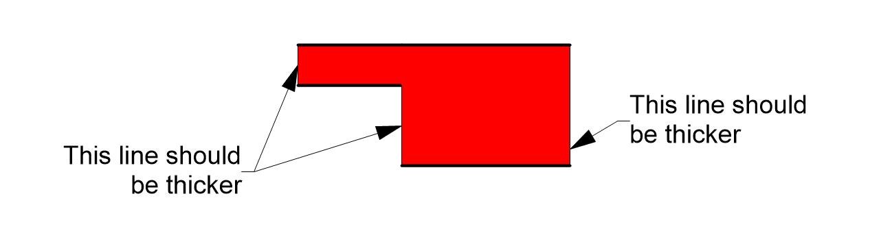
Hello, I have a simple problem. I want to connect two walls with the same component (all attributes are connected with a class) to create one wall with various thickness. As you can see in the picture VW recognises ends correctly, but uses two different line styles - for the outer and inner face as defined in the class and for the endings much thinner. Any hints? WallConection.vwx

-
@Peter Neufeld, thank you so much for your time. I will do some more research and probably report this.
-
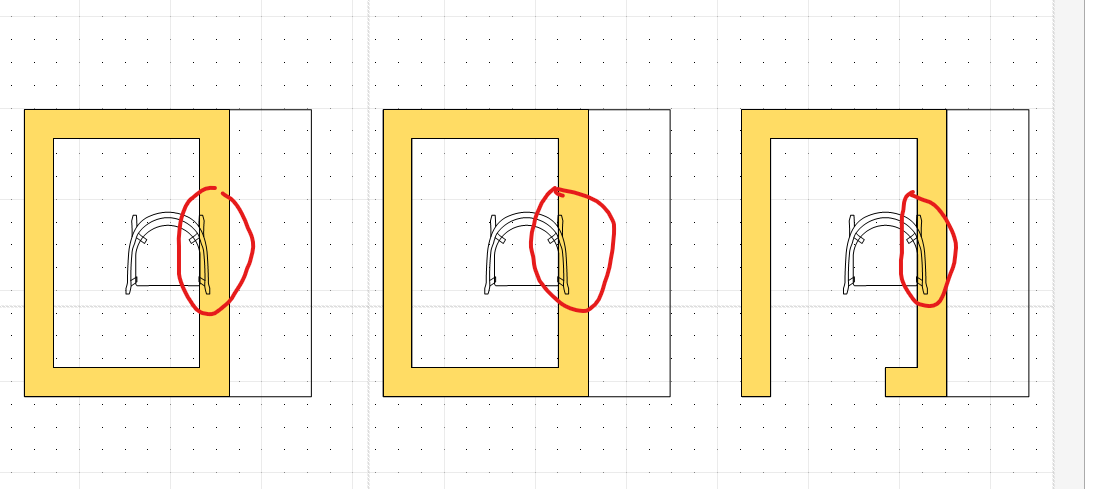
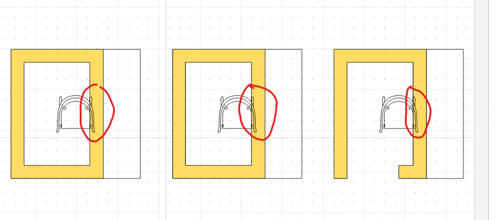
@Peter Neufeld, I have checked this one and still it is not the answer. No matter how you manage visibility settings, objects that should be partially covered by a solid are visible like they would be on top of solid, not inside it. See the picture in the attachment.
-
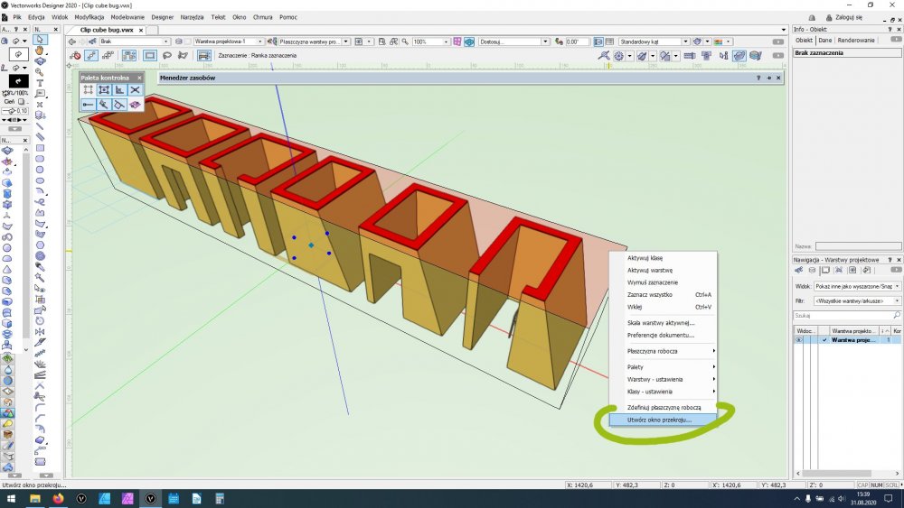
So I am using clip cube to create some kind of horizontal section (like a plane, but by using clip cube). The thing is that if I use clip cube to create plan (horizontal section) there is a bug. But if I use the same clip cube to create classic section (lets say vertical) it works perfectly. Clip cube bug.vwx
-
@Peter Neufeld, thank you for your time anyway 🙂 I really hope I will find where the problem is.
-
It is not a solution. By changing cut plane to infinite you just show the top view. If I add "slab" to my solid (add an extrusion on top to mimic slab top view) chair is still not visible. More accurate model in attachment. Clip cube bug.vwx
-
@Peter Neufeld, thanks for answer. But it is not the 3D view or OpenGL problem. My case is visible on the sheet layers (I have prepared one with explanations). You can see that there are differences between section viewports that go through solid with a hole and solid without a hole. I cannot see the chair in the section viewport on the sheet layer. Changing view from standard to orthogonal does not work. If I change rendering style to "Dashed Hidden Line" it works (chair is in place), but using option "Hidden lines" chair is gone some how but it should be visible.
-
v2020 Group node does not work as v2019 Group node
Grzegorz Krzemien replied to Grzegorz Krzemien's topic in Marionette
I think the same. This really looks like a bug or some kind of "work in progress" thing that was not finished. I will report it and maybe it will be changed in the next patch. It is a quite important node so it should be fixed as soon as possible. @AlHanson, @the frog - thank you so much for your time 🙂 -
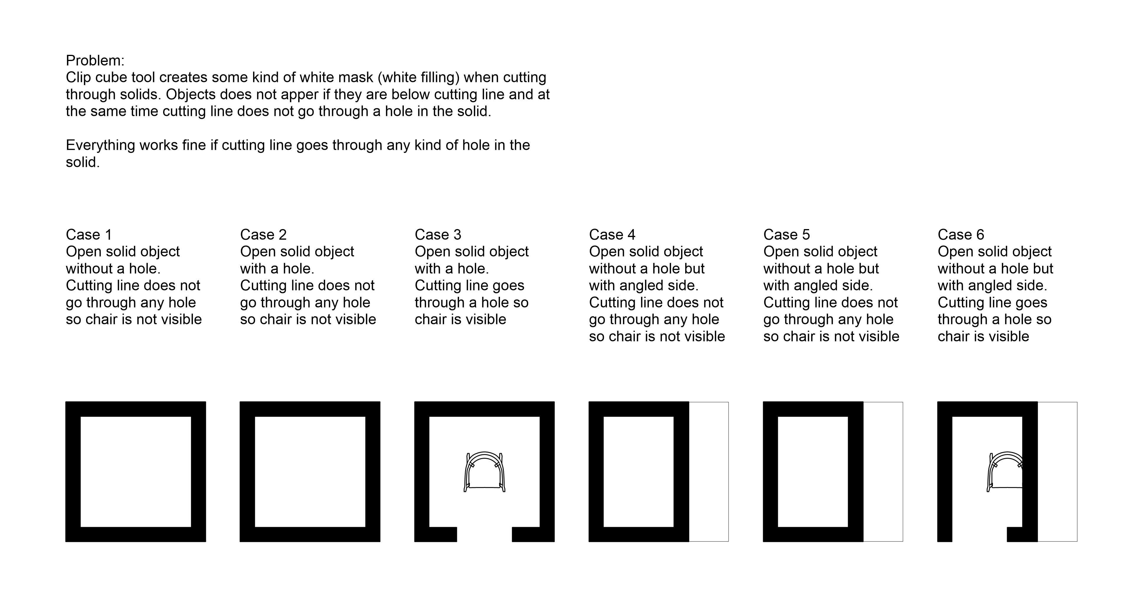
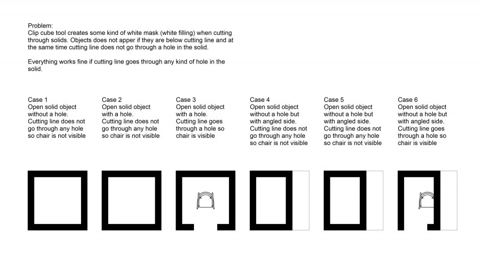
Hello, I have a problem with Clip Cube tool. While using clip cube to create sections it creates some kind of white mask (white filling) when cutting through solids. Objects does not appear if they are below cutting line and at the same time cutting line does not go through a hole in the solid. Everything works fine if cutting line goes through any kind of hole in the solid. Hope someone can help mi with that or at least explains why it works like this. Example file in attachments. Clip cube bug.vwx
-
Hello, I tried to recreate my old script from 2019 and I have encountered strange thing. Group node in v2020 is different than Group node from v2019. In my example new node (v2020) does not work (gives 0 values), while v2019 node works fine. Does anyone has an idea why this node needed to be changed any why it does not work now? Both nodes in example file. Group test.vwx
-
Thanks, I need to check this, but anyway can't wait for VW2021 then 🙂
-
@Pat Stanford Values in OIP does show unit marks. Values without OIP does not.
-
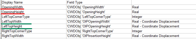
@Pat Stanford, I used your script and got results (attached file). 'CWDObj'.'OpeningWidth' and 'CWDObj'.'OpeningHeight' are "REAL", so they should be numbers, but they do not change according to current document units. 'CWDObj'.'OIPOpeningWidth' and 'CWDObj'.'OIPOpeningHeight' are "Real - Coordinate Displacement". I have no idea what this kind of data type is, but it is working. Information is correct in terms of document units. Do you know the difference between these two data types? I can not use math operations on both results, so it looks like they are not numbers.
-
@Pat Stanford, thanks for a hint. Yes, there is a second formula #CWDObj#.#OIPOpeningWidth# that is working fine, but math operations still do not work. My formula looks like this: #CWDObj#.#OIPOpeningWidth# - 10 Maybe I am missing something like: #CWDObj#.#OIPOpeningWidth# - #10# ?
-
Hi all, I have a problem with Data Tags. My custom data tag should return window's width. But despite the document units, data tag always shows number in millimetres. Option "document units" is unavailable in edit data tag mode. In my file there is a second tag that works correctly. Second question is, if it is possible to do simple math operations inside data tag definition. E.g. I want to show in my tag "windows width" - 10. I tried to use following formula "#CWDObj#.#OpeningWidth# - 10" but it is recognised as text and displays as 1000 - 10 on my tag. Any hints? DataTags.vwx
-
Hi all, Is there any way to read a NURBS curve direction in Marionette, like we can using PIO? I would like to get direction vectors on certain points of any NURBS curve, but I can't find any node or vs.function that I can use. Any hints?
-
Hi, Try "Set Char Properties" node in Objects-Text.
-
@sully8391 The easiest way to create custom node is to modify existing one. You can double click on any node to check what is inside and change it. Keep in mind that you should delete the first line and change name of the new node in order to save your changes. Here is my example of what I think you have tried to do. SimpleLoopNode.vwx
-
I think MRoth has given you a nice hint. You can try to use some functions to create non-linear values.
-
Help with understanding List on creating a Truncated Cone
Grzegorz Krzemien replied to Todd Drucker's topic in Marionette
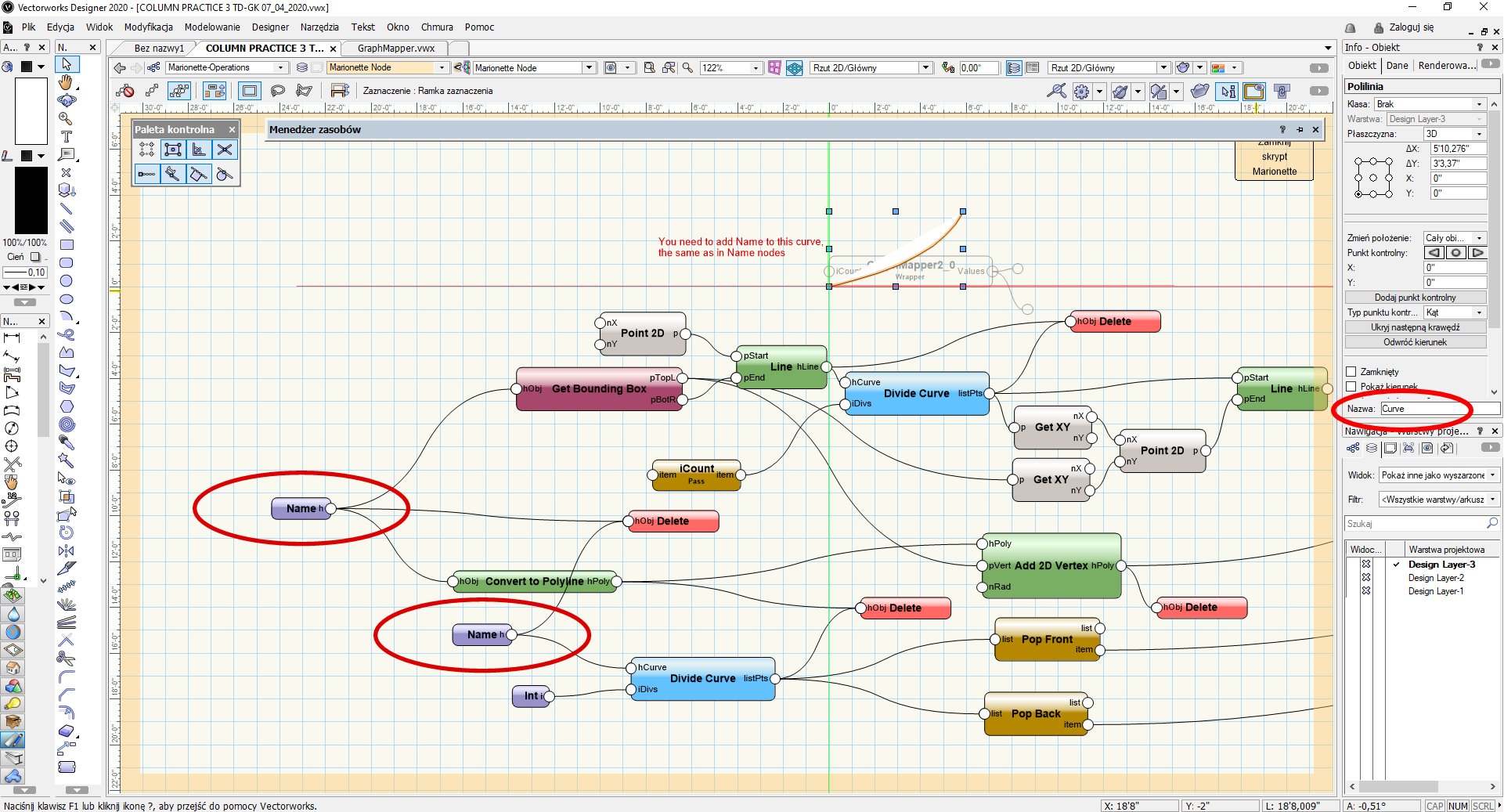
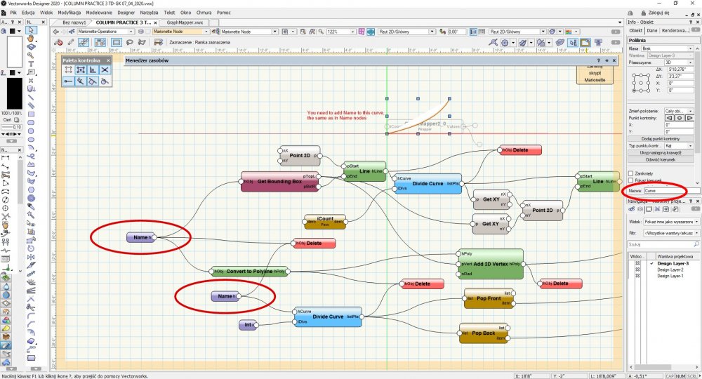
@Todd Drucker To get more "exponential" shape you will need exponential function. Here you have my very first attempt to build something like graph mapper. Inside a wrapper called "GraphMapper2.0" there is a curve that can be modified as desired. Wrapper generates set of values based on y values of that curve. Next we can use this values to create non-linear modifiers for scale vector. Unfortunately, every time you copy this wrapper you need to add name to the curve inside the wrapper, the same as nodes name inside wrapper. But it should work, you can play around it by changing ValueMax, and ValueMin or changing the shape of the curve. Have fun. COLUMN PRACTICE 3 TD-GK 07_04_2020.vwx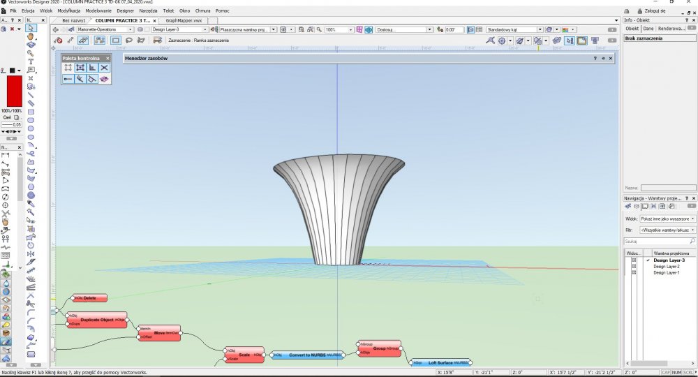
-
@sully8391 I think that you need to rethink what you would like to do. Your network works like this: 1. create a range of numbers 2. Multiply these numbers by phi 3. Use this list of numbers as Y coordinate. This network returns a range of evenly multiplied numbers (each base number is multiplied by phi separately) so distances between rectangles are constant. E.g. 1st. point (0,0) 2nd. point (0, 161) where Y = 100*1,61 3rd. point (0, 322) where Y = 200*1,61 4th. point (0, 483) where Y = 300*1,61 and so on... You can see that distance between points is constant and is equal to step*phi As I understand you want to make a network that distributes rectangles at different distances using phi, yes? This will require different approach. You need to multiply a previous distance. E.g. 1st. point (0,0) 2nd. point (0,161) where Y = 100x1,61 3rd. point (0, 259) where Y = 161x1,61 4th. point (0, 417) where Y = 259x1,61 and so on... You can spot the difference. Hope you'll make it. If you have any questions just ask.