wclights
-
Posts
14 -
Joined
-
Last visited
Content Type
Profiles
Forums
Events
Articles
Marionette
Store
Everything posted by wclights
-
Extrudes only rendering solid from certain angles.
wclights replied to wclights's question in Troubleshooting
Still happening in the original file with SP4. Possibly just SOL on that file. When I copy into a clean file now I cannot reproduce the issue, even though when I did that as one of my own troubleshooting things before posting it would happen every time. Only difference is I am on SP4 now so that probably did fix the issue. Won't help with the current show as I'm too far into the process to start fresh, but at least I can breathe easy knowing I probably won't run into this again on my next file. Thanks all! -
Extrudes only rendering solid from certain angles.
wclights replied to wclights's question in Troubleshooting
Unfortunately, that did not solve the problem. Hopefully they get a patch out soon, but I bet they're just gonna sit on it until they release 2023. -
Hi all, I am trying to do some preview rendering in Vectorworks 2022 and I am finding that Vectorworks is hollowing out my extrudes, but only from certain angles. If I render Final Quality from Top View or from high front angle it shows my extrudes as solids, but then if I move the camera left or right even a bit it won't render. If I go to Shaded I can see from the working angles that the extrudes are solid and that from the not working angles they are becoming hollow. I made sure my extrudes were closed (I even redrew them just to be sure) and quitting and rebooting still produce the same results. I am referencing the extrudes from other files, but it's happening to them in the original files as well. When I tried drawing a new extrude in my main file the same problem persisted. Has anyone run into this bug and have any helpful suggestions? It's not world ending, but it's certainly annoying to find such a detrimental bug this far into the release. Thanks, Will
-
Can I reference OIP data in a Record Format field?
wclights replied to wclights's topic in Entertainment
Hi Sam, Sorry to get back to you a year later. Data Tags look to be the answer to my particular quest. To answer your question: I have my own personal line set schedule for my light plots that I designed and enjoy the look of very much. It's nothing fancy, but it's mine. The problem was while having it as a symbol I could drop in to any drawing was handy, any time I wanted to edit the info I had to jump into the symbol and edit the text fields in there. I had all the text fields linked to record formats so once I was in the symbol it was easy enough, but I wondered if there was a way to automate the data like trim height and "to plaster line" since I draw my plaster/center/stage floor on 0/0/0. Nowadays I usually work in the same handful of theatres so rather than use a symbol I can just make base files with individual line set schedules designed for each space and now I know I can use data tags instead of record formats to make the info auto populate for me. - Will -
Can I reference OIP data in a Record Format field?
wclights replied to wclights's topic in Entertainment
Maybe data tags are what I want then, I haven't used them before. An example of the ideal functionality for me is I am making a line set schedule and I want that to have the trim height of the batten which in my drawing is the Z coordinate of the pipe symbol. In this example I want the record to reference the Z coordinate so that if I change the Z coordinate of the pipe it updates the line set schedule. -
Hi all, I am trying to improve my workflow with my line sets and I am wondering if it is possible to connect OIP data like Position Name and Z value to a custom made Record Format. Basically I am trying to eventually improve my line set schedule work flow, and I thought Record Formats might be the key, but I don't want to have to update the data in the OIP and a separate Record Format. Since a lot of the Record Format data should match what's in the OIP I was hoping there might be some way to reference it similar to referencing another cell in Excel. Or am I going down the completely wrong rabbit hole? Thanks for any help in advance!
-
@a2collin If only it were that simple. Technically that would work but you would just have two versions of the plot one that was focused with no color or gobos and one that was just pointed straight down but with all the color and gobos. In my opinion the best approach is MVR and then adding color manually in Vision, but I have had issues assigning gobos to MVR fixtures so I have to import those as ESC and manually focus. Also have had some fixtures like parnels crash the program while trying to manually add color so be ready for that possibility and save often.
-
Currently MVR is the only version that will export focus data, however, ESC is the only version that will export color and gobo data so you are kind of stuck with an either/or. MVR should have exported your focus data, but I think you need to export your focus points as well or it won't work. In my experience they import into Vision as invisible in the MVR format so you could give that a go.
-
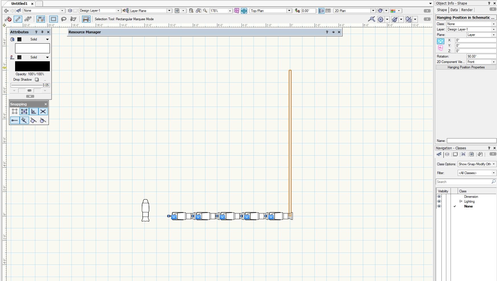
I would also love any insights into a more efficient workflow for this. Same as above my normal workflow would be something along the lines of draw lighting pipe, rotate to standing, convert to hanging position, hang lights from there. However, the schematic front view when I do this places the lights and position at a perpendicular angle from each other. The workaround so far is create the light pipe, create the schematic view in top view, rotate the pipe to standing, place my instruments. If I try to convert my light pipe to a hanging position before instruments but after schematic view the schematic no longer works as it still references the light pipe which technically only exists as the base for the hanging position so any lights added do not show up.
-
Hi all thanks in advance for any help. I am having a lot of trouble getting MVR and just Vision in general to work. I take my Vectorworks file and I export to MVR. Then I open Vision and try to open the MVR. Vision takes a second and then crashes with no error. I try Send to Vision (which as I understand it sends it as an ESC) and that actually opens, but it's missing some lights. Regardless, even when I get the ESC to open it doesn't have color info and it isn't controllable through the eos nomad software even though I have my patch set up, trying both Artnet and sACN. The Vision help page is laughable. Does anyone have any insights into what I may be doing wrong or possibly an online guide I can possibly use to get moving on this? Thanks again.
-
Can MVR import Focus Points for conventional fixtures from Vectorworks so they are already focused on import? I haven't been keeping up lately, but this is the main feature I have been hoping for for a while now.
-
So by reading this forum I have figured out how to use the new Title Block tool, but I haven't been able to figure out how to create my own custom title block border that I can open in multiple files. I can create a new border, import my saved graphic, add all custom project data fields I want included, and then link each piece of text to the proper title block data. Presto, I have a working title block...in that one document. I really don't want to have to create the custom data fields in every new file, but I cannot for the life of me figure out how to import my already ready to use title block. I have tried saving the updated graphic and importing that, which almost works except it fails to import the records so it becomes a bunch of empty, un-linked text fields. Am I missing a step here?
-
Hanging Positions don't assign Heights anymore.
wclights replied to markdd's question in Troubleshooting
So about half the time my light will associate with the z-position, but even if it does I have found if I change the design layer the instrument is on (like when I accidentally draft it into the wrong layer to begin with) it almost always resets the z-position to 0". -
Hanging Positions don't assign Heights anymore.
wclights replied to markdd's question in Troubleshooting
I have this same question. I cannot even get my hanging positions made from light pipes to assign a Z value. That was like 90% of the value of converting lighting pipes for me. Hoping it is just a bug. Worth noting that if I change the height of a hanging position with lights already on it they do adjust their Z by that much, so it is tracking once it's dropped just not attaching itself to the Z value initially.