


Jesse Cogswell
-
Posts
634 -
Joined
-
Last visited
Content Type
Profiles
Forums
Events
Articles
Marionette
Store
Posts posted by Jesse Cogswell
-
-
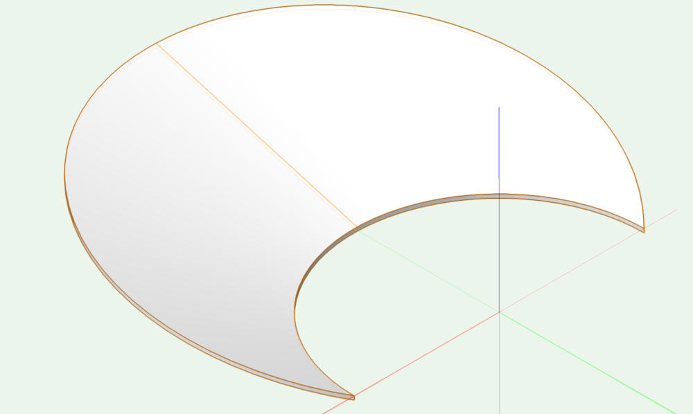
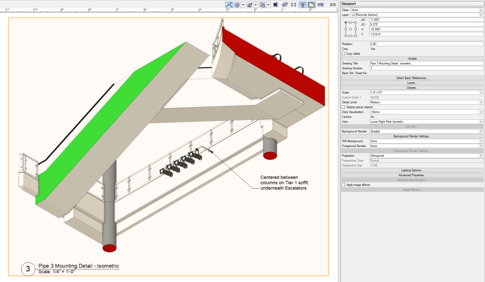
There's a pretty easy way to create a "bowl" shape in this instance that I've used in the past for orchestra floors using Extrude Along Path and Subtract Solid, though I've never encountered a bowl shape going into a curved house wall, so this method might not get accurate results on the edges:
Path matching US side of orchestra floor ("Bowl"):
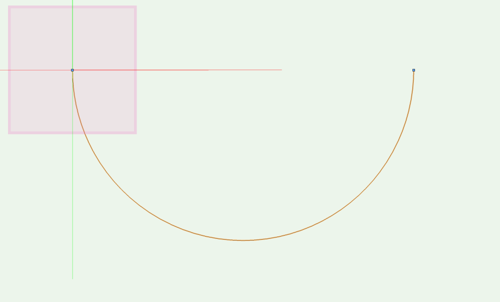
Profile matching house rake and floor thickness (6" in this case):
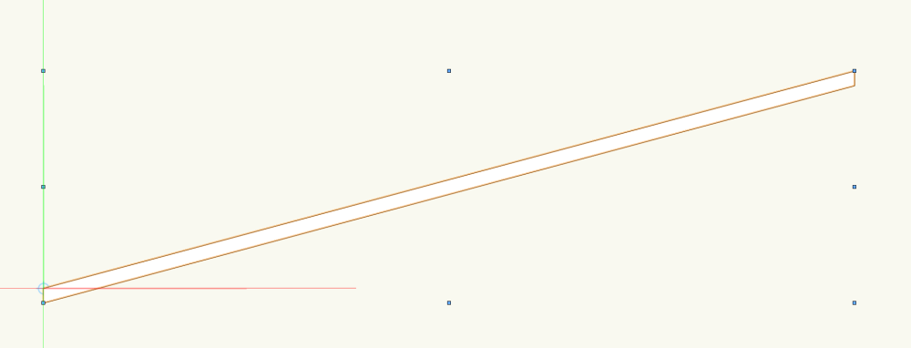
Extrude Along Path Result:
Creating Polyline for Extrude for Subtraction:
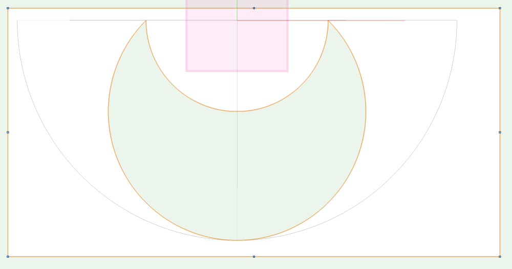
Final Shape Top View:
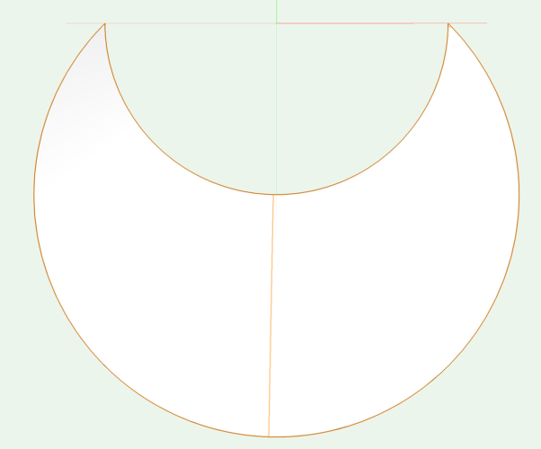
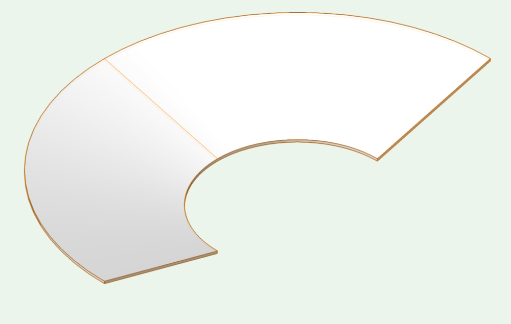
Final Shape Right Rear Isometric:
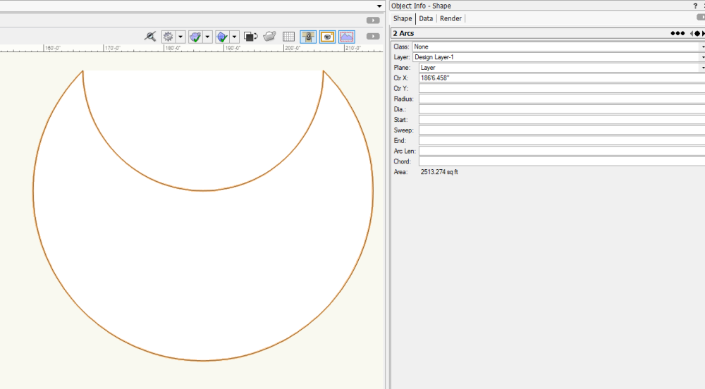
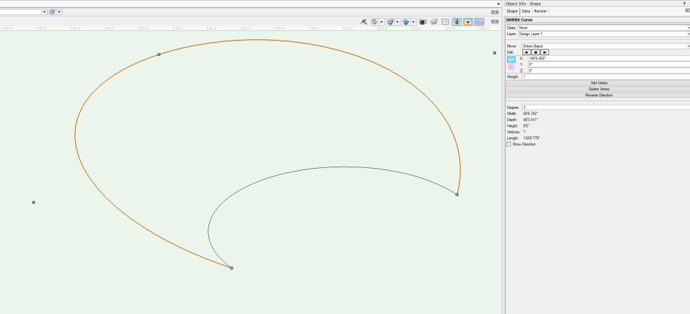
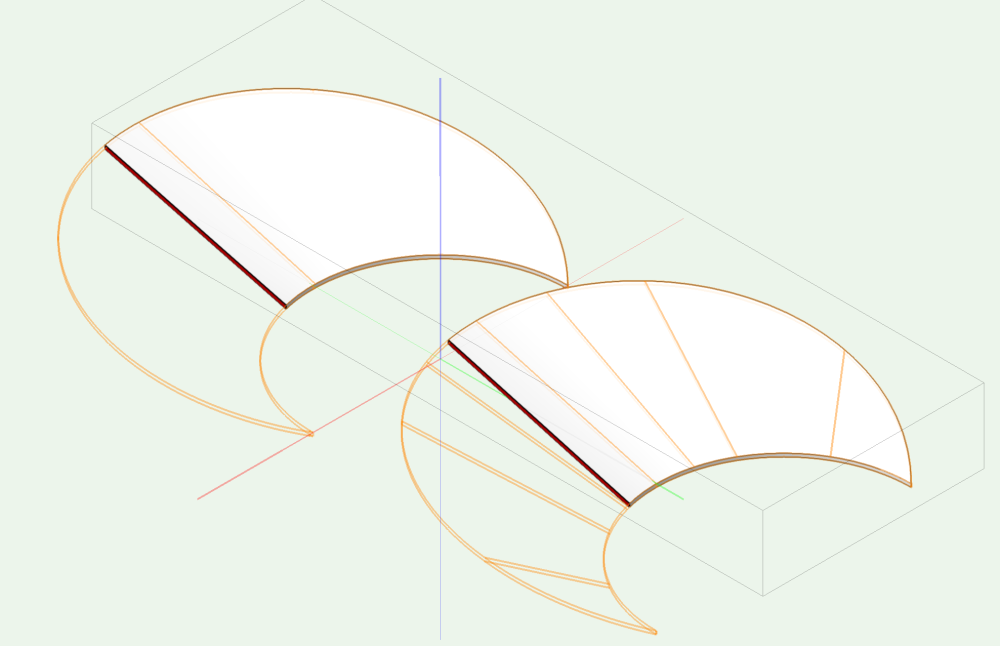
There is another way to do this using NURBS that could also work (and might be a bit more accurate):
Two Arcs representing each curve:
DS NURBS Curve set to Z height of back of house (8'-0" in this example):
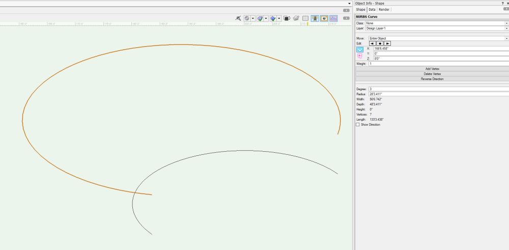
DS NURBS Curve edited so that US points match with lower NURBS
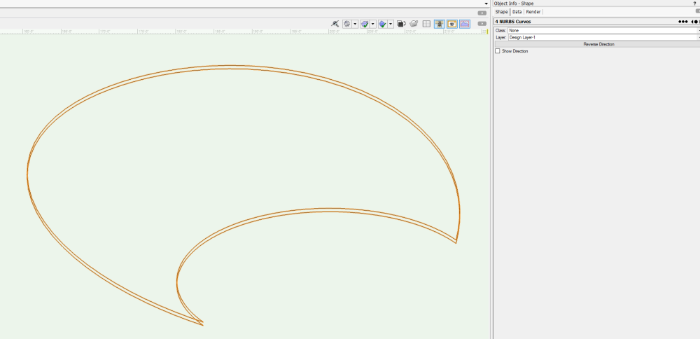
NURBS Curves Ctrl+click-and-drag 6" lower to duplicate, ending with 4 NURBS Curves:
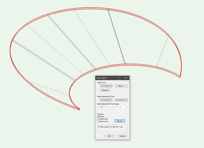
Loft Surface Tool in No Rail Mode, selecting 4 NURBS Curves:
Ungrouping Revealing 4 NURBS Surfaces:
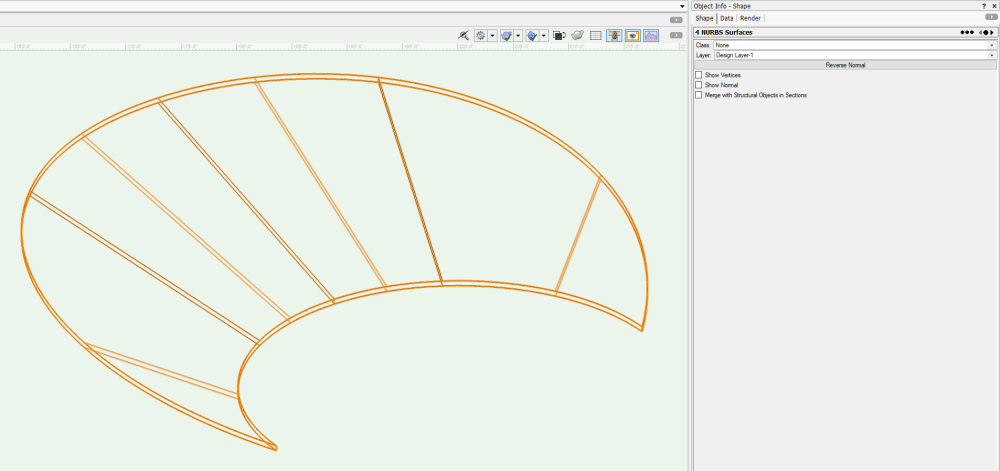
Creating Solid by using Model - Add Solids:
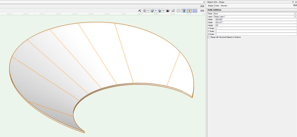
Both methods produce "Water-tight" solids, good for Section Viewports:
-
 3
3
-
-
You need to use GetParametricRecord on the object then GetName on the result. Something like:
PIOName:=GetName(GetParametricRecord(h));
The other way to do it is to use GetRecord with the index set to the last record attached to the object, which will always be the parametric record. Something like:
PIOName:=GetName(GetRecord(h,NumRecords(h)));-
1
-
-
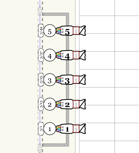
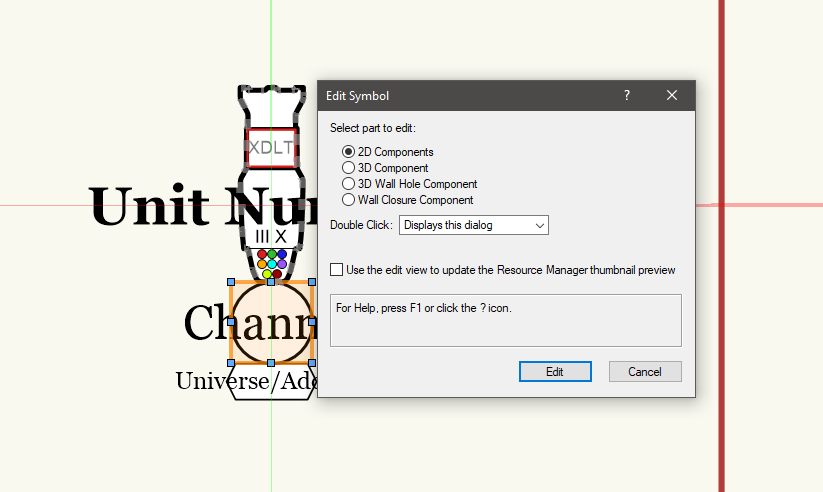
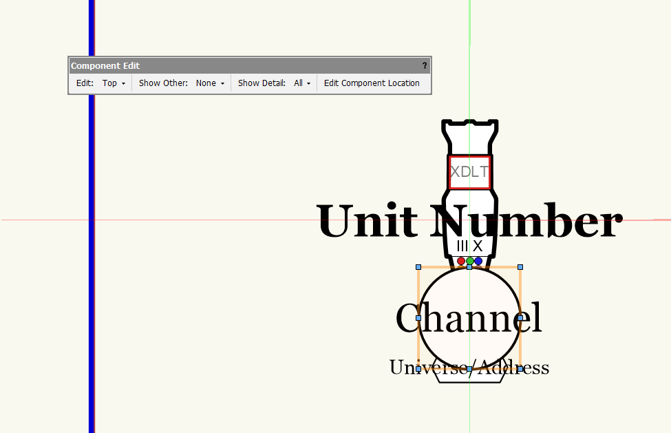
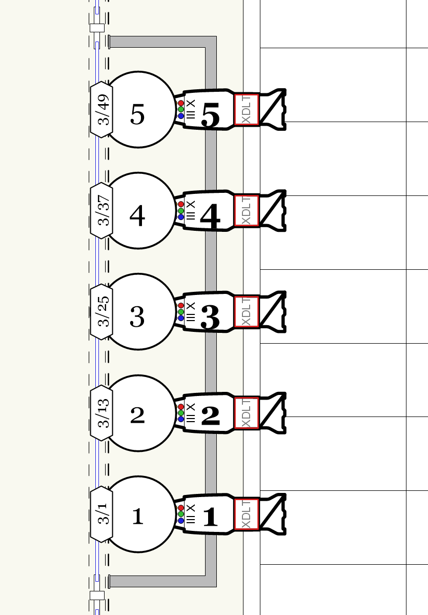
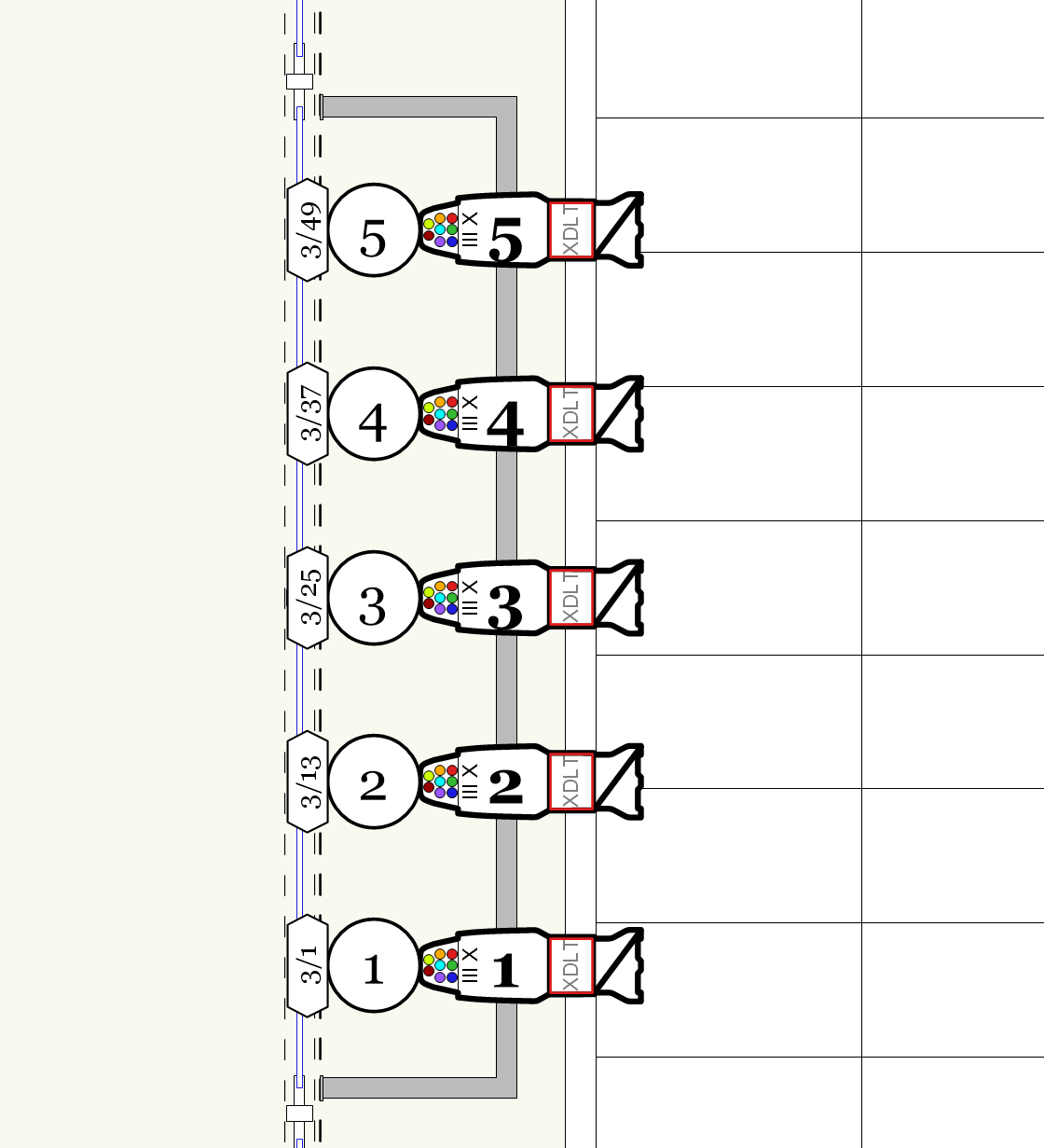
Are you editing the label legend in through the Resource Manager or the container object? I just did a quick test and all of my containers update as soon as I leave the Edit Symbol on the container on VW2023 SP5. Based on your first post, I suspect that you are trying to change the container scaling by editing the Label Legend symbol and scaling the container through the OIP. This will not work. As @klinzey noted, those container symbols are just for reference and have no bearing on the final application of the label legend. What you need to do is edit the container symbol itself. You can do this while editing the Label Legend, just double click on the container you want to change the scale of, select 2D Components in the Edit Symbol dialog box, and scale the container object from there. When you exit the symbol edit, you will still be in the Label Legend edit, but it will dump you into a 3D view for some reason. Just reselect the Top mode from the Edit Component widget.
Initial fixtures with non-scaled container:
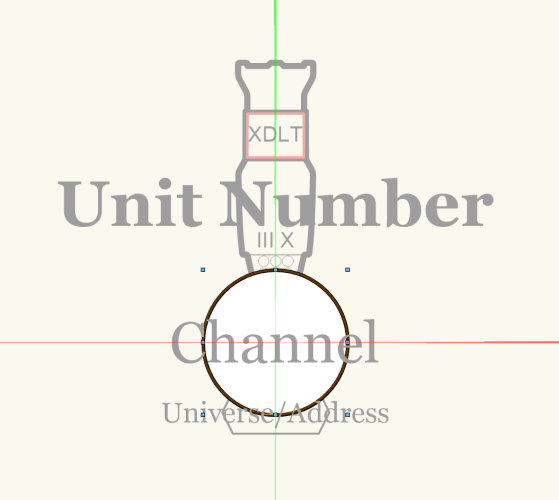
Label Legend Edit with channel circle selected:
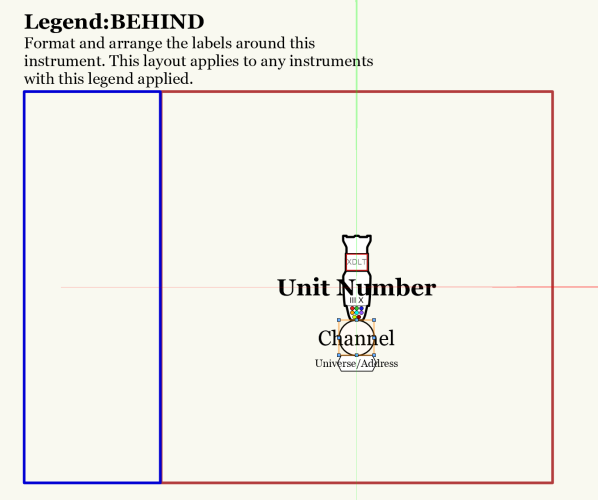
Double-clicking the circle container:
Circle scaled up 1.5x using Scale command:
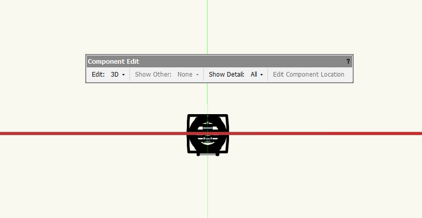
Initial view after clicking Exit Symbol:
Reselecting Top on widget restores Label Legend Edit, showing scale change:
Change instantly reflected on fixtures after exiting Label Legend Edit:
-
1
-
-
You can turn this off by unchecking Confirm before save in the Autosave tab of the Vectorworks Preferences.
-
1
-
-
To get the buttons to collapse, you need to make sure that they are indented as well. You would use vsoWidgetSetIndLvl(<widget ID>,1); The indent ID is the number that you have assigned to the button from the kObjOnInitXProperties event. In my example file, it would be the kButton1ID through kButton3ID, which were 3001 through 3003. So you would have something like vsoWidgetSetIndLvl(3001,1); to indent the first button. If you borrowed my SetIndent procedure from my example, you could use it to do all of the buttons at once, which is what line 404 is doing in the example: SetIndent(kButton1ID, kButton3ID, 1); In terms of setting the size of the buttons, you could ramp up the indent until the button lines up with the drop-down, but I think it tops out at an indent of 3, which wouldn't be enough to line up with the drop-down.
To show or hide the buttons based on parameter settings, you would put the code inside the kObjOnWidgetPrep event using the vsoWidgetSetVisible procedure. Anytime you want to change the OIP for a single instance of a PIO, such as enabling or disabling or hiding widgets and parameters, you must put in a kObjOnWidgetPrep event and have the code there. That event runs anytime the object is selected while the kObjOnInitXProperties event runs when an object is created, so making changes to visibilities in the initialization event will reflect those changes to ALL instances of the PIO versus just the one.
-
That's what I have in my second post: newHeight:=(Random * (maxValue - minValue)) + minValue;
-
I had a thought about looking into the Marionette Random node to see how they did it and have revised the code to work without the Python bits. The advantage to this code is that you can now totally input a range in whatever set of units you want (like 6'3" for example).
PROCEDURE RandomizeHeights; {* Randomizes heights of all selected objects on the active layer Developed by: Jesse Cogswell Date: 7/27/2023 Revisions: 7/27/2023 Removed Python code *} VAR dialog,layoutDialog:LONGINT; minValue,maxValue:REAL; PROCEDURE RandoHeight(h:HANDLE); {Randomizes height of given object} VAR newHeight:REAL; symbolLoc:POINT3D; BEGIN GetSymLoc3D(h,symbolLoc.x,symbolLoc.y,symbolLoc.z); newHeight:=(Random * (maxValue - minValue)) + minValue; Move3DObj(h,0,0,0 - symbolLoc.z); Move3DObj(h,0,0,newHeight); ResetObject(h); END; FUNCTION DrawDialog(sDiaName:STRING) : LONGINT; {Creates dialog box and returns dialog ID} CONST kStaticLength = 14; kEditLength = 10; VAR dia:LONGINT; BEGIN dia:=CreateLayout(sDiaName,FALSE,'OK','Cancel'); CreateStaticText(dia,11,'Min. Height:',kStaticLength); CreateStaticText(dia,12,'Max Height:',kStaticLength); CreateEditReal(dia,21,1,3,kEditLength); CreateEditReal(dia,22,1,3,kEditLength); SetFirstLayoutItem(dia,11); SetRightItem(dia,11,21,0,0); SetBelowItem(dia,11,12,0,0); SetRightItem(dia,12,22,0,0); DrawDialog:=dia; END; PROCEDURE DialogHandler(VAR item,data:LONGINT); {Handles dialog box} VAR BSB:BOOLEAN; currentLayer:STRING; BEGIN CASE item OF SetupDialogC: BEGIN END; 1: {OK} BEGIN currentLayer:=GetLName(ActLayer); BSB:=GetEditReal(dialog,21,3,minValue); BSB:=GetEditReal(dialog,22,3,maxValue); ForEachObject(RandoHeight,((SEL) & (L=currentLayer))); END; 2: {Cancel} BEGIN END; END; END; BEGIN dialog:=DrawDialog('Enter Range'); layoutDialog:=RunLayoutDialog(dialog,DialogHandler); END; Run(RandomizeHeights);-
1
-
-
I think I might have figured out a way to do this. Unfortunately, the Vectorscript Random function is super limited and doesn't have a way to select a random number from a range (though I suppose someone smarter than me can write up a function using the existing Random function). But luckily for us, Python does have a method of doing just that. So with a little help from our friend PythonExecute to use python code in a Vectorscript.
The script below will open a dialog box allowing the user to specify the minimum and maximum value in document units (so if you are in feet and inches, type in inches. Don't do something like 2'6", because the Python code won't really know what to do with that), then generates a new height using the Python random.uniform method and then applies that new height to a given object using a ForEachObject call. The code as written will execute on all selected objects on the currently active layer.
The code has been very lightly tested in metric and freedom units and should work on symbols as well as Plug-in Objects.
PROCEDURE RandomizeHeights; {* Randomizes heights of all selected objects on the active layer Developed by: Jesse Cogswell Date: 7/27/2023 Revisions: *} VAR dialog,layoutDialog:LONGINT; minValue,maxValue:REAL; FUNCTION RandRange(rMin,rMax:REAL) : REAL; {Uses Python Uniform Random method to generate a random number between given range} VAR output:REAL; BEGIN PythonBeginContext; PythonExecute('import random'); PythonExecute('import vs'); PythonExecute('min = vs.GetVSVar("minValue")'); PythonExecute('max = vs.GetVSVar("maxValue")'); PythonExecute('output = random.uniform(min,max)'); PythonExecute('vs.SetVSVar("output",output)'); PythonEndContext; RandRange:=output; END; PROCEDURE RandoHeight(h:HANDLE); {Randomizes height of given object} VAR newHeight:REAL; symbolLoc:POINT3D; BEGIN GetSymLoc3D(h,symbolLoc.x,symbolLoc.y,symbolLoc.z); newHeight:=RandRange(minValue,maxValue); Move3DObj(h,0,0,0 - symbolLoc.z); Move3DObj(h,0,0,newHeight); ResetObject(h); END; FUNCTION DrawDialog(sDiaName:STRING) : LONGINT; {Creates dialog box and returns dialog ID} CONST kStaticLength = 14; kEditLength = 10; VAR dia:LONGINT; BEGIN dia:=CreateLayout(sDiaName,FALSE,'OK','Cancel'); CreateStaticText(dia,11,'Min. Height:',kStaticLength); CreateStaticText(dia,12,'Max Height:',kStaticLength); CreateEditReal(dia,21,1,0,kEditLength); CreateEditReal(dia,22,1,0,kEditLength); SetFirstLayoutItem(dia,11); SetRightItem(dia,11,21,0,0); SetBelowItem(dia,11,12,0,0); SetRightItem(dia,12,22,0,0); DrawDialog:=dia; END; PROCEDURE DialogHandler(VAR item,data:LONGINT); {Handles dialog box} VAR BSB:BOOLEAN; currentLayer:STRING; BEGIN CASE item OF SetupDialogC: BEGIN END; 1: {OK} BEGIN currentLayer:=GetLName(ActLayer); BSB:=GetEditReal(dialog,21,3,minValue); BSB:=GetEditReal(dialog,22,3,maxValue); ForEachObject(RandoHeight,((SEL) & (L=currentLayer))); END; 2: {Cancel} BEGIN END; END; END; BEGIN dialog:=DrawDialog('Enter Range'); layoutDialog:=RunLayoutDialog(dialog,DialogHandler); END; Run(RandomizeHeights); -
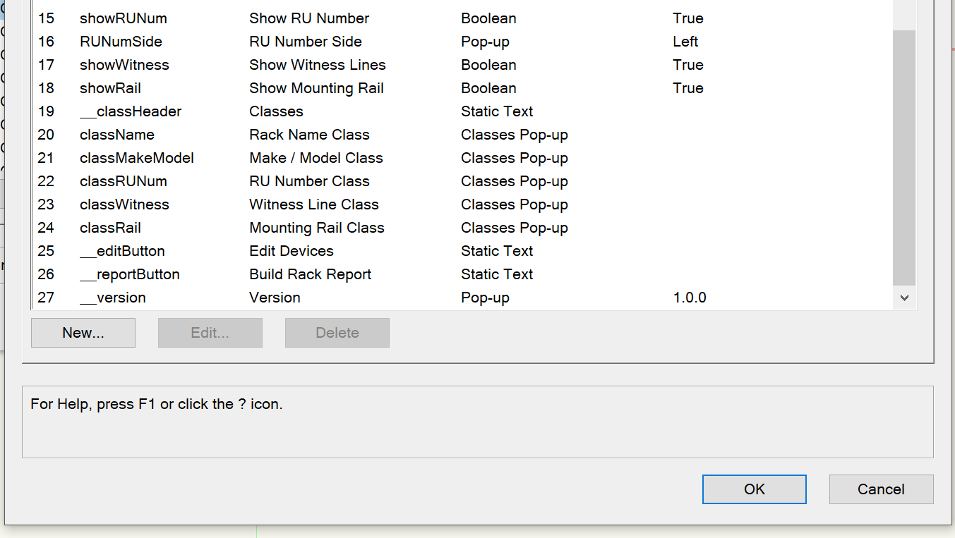
Making a plug-in event-enabled shouldn't affect class pop-ups in the slightest, I use them often in my plug-ins. If you don't mind, could you post the code from your kObjOnInitXProperties event? There is a chance that something isn't set quite right and the parameter isn't populating correctly.
Also, I don't know if it's a Mac thing, but my Parameters page lists the Type as Classes Pop-up rather than Class as shown in your example. Also pro-tip in case you are unaware, if you leave the Default field blank on a classes pop-up, the parameter will inherit the class of the PIO itself, which can be handy in some instances.

-
There's some kind of bug when using the Insert Code button when making a post. If that code contains C h r() in it (without the spaces), submitting the post will send you to a 403 Forbidden page, and when double-clicking the code block to edit it, you will get an error message.
-
The key lies in the following three lines of code, the top two are part of the global constant declaration block and the final one will be part of your kObjOnInitXProperties event in the main driver.
{Event Constants}
kWidgetGroupMode = 81;
kWidgetGroupModeAutomatic = 2;

{kObjOnInitXProperties}
result:=SetObjPropCharVS(kWidgetGroupMode, C h r(kWidgetGroupModeAutomatic));
You will also need to set the indent of the things to collapse using the vsoWidgetSetIndLvl function. I have a procedure called SetIndent in my code that allows you to specify a start and an end and will indent everything in between. You'll need to do this for parameters and buttons.
EDIT:
There's something weird with the forum's code box, it won't let me type in the code for setting the character, so remove the spaces in between C h r in the code.
-
Sorry, I posted the VW2019 version of the plug-in which didn't have that code since VW2019 doesn't support that feature. I've updated the code to include it and attached it below.
-
That's covered in my example linked above. It's easier than you might think, you just need to toggle it on and then set intents on your parameters.
-
Could you please attach your .vso file so that we can see the plug-in definition settings? My guess is that your objectName argument or the parameterName argument doesn't line up with the parameter names in the plug-in definition, but I can't see that without the object itself.
-
1
-
-
@SamIWas I wrote up an example of an Events Enabled plug-in a couple of months ago that includes the code for a pretty nice symbol picker (as well as the default vsoButtonGetResource function). I've notated most of it with what the code is doing, have a look and let me know if you have any questions.
-
I keep an old copy of VW2019 around that I use strictly for plug-in development to maintain backward compatibility as best as possible. Because Vectorscript really hasn't changed much in the last few years, I think there's only one or two of my plug-ins that require something newer than VW2019, and I can use the {$IF} compiler directive to skip blocks of code that correspond with newer versions.
The real hurdle is keeping the plug-ins up to date across all installed instances of VW. I currently have 2019, 2020, 2021, 2022, and 2023 all installed due to different clients being on different versions (I 100% prefer to keep a drawing native to what the client is using rather than backsaving from a newer version), so when I make an update I have to remember to copy that plug-in over to the other user folders. I've also been known to make adjustments in an immediate drawing on a newer version, then copying and pasting the code back in to the VW2019 plug-in to update the "base." As long as you're not making drastic changes to the plug-in definition (changing parameters or plug-in strings), it's very quick and straightforward.
-
1
-
-
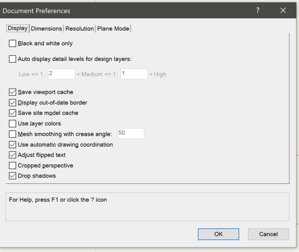
If you want to stay in Perspective mode but want to lose the crop, open the Document Settings and uncheck Cropped Perspective. It should be there in any version of Vectorworks going back until at least 2015, and I want to say it was there going back as far as 2010, but don't have an old install to check.
-
1
-
-
What you'll want to do is use ValidNumStr to convert the value.
-
1
-
-
I did a write up a while back that might help you.
If you have a decent grasp of Vectorscript, building PIOs is very simple. The biggest changes are working through the Plug-in Manager (if you've primarily written document scripts) and dealing with parameters. You basically have to define all of your parameters at the outset, then access the parameters by putting an uppercase "P" in front of the variable name (something like width:=Pwidth).
-
1
-
-
@The Hamma After doing some testing, I figured it out. The issue is that I was using InsertImagePopupObjectItem to populate the thumbnail, which populates using named objects. Unfortunately, the external resources aren't named objects within the drawing, so while the resource list is feeding the names in properly, the thumbnail popup doesn't know what to do with it.
But don't despair, you can use InsertImagePopupResource instead! What you would need to do is use the script as originally written in my example to build the list for symbols in the drawing, then build a new resource list from within the dialog handler with the external library stuff (use a negative folder number to restrict to just get the external library since the document symbols are already handled), and feed that into InsertImagePopupResource. It won't be sorted by anything, but it will get the symbols at least. I can't seem to find a way to pull a resource's source file, but if there's a way to do so, you could theoretically add dividers by source file to the thumbnail popup.
The dialog handler in my testing looked like this, you should be able to change the BuildResList code to suit your needs:
{-----------------------DIALOG HANDLING---------------------------------------} PROCEDURE SymbolDialogHandler(VAR item,data:LONGINT); {Handles Select Symbol dialog box} VAR i,j,int,totalParents,totalResources:INTEGER; str:STRING; resList,numItems:LONGINT; BEGIN CASE item OF SetupDialogC: BEGIN PopulateResourceArray(kSymbol,totalParents,totalResources); IF(totalResources>0) THEN BEGIN FOR i:=1 TO totalParents DO BEGIN int:=InsertImagePopupSeparator(dialog,31,parentArr[i]); FOR j:=1 TO totalResources DO BEGIN str:=resourceArr[i,j]; IF((str<>'') & (GetObject(str) <> NIL)) THEN int:=InsertImagePopupObjectItem(dialog,31,str); END; END; i:=1; {-----------------------NEW CODE------------------------------------------------------------------------------------} int:=InsertImagePopupSeparator(dialog,31,'External'); resList:=BuildResourceList(16,-116,'',numItems); FOR i:=1 TO numItems DO int:=InsertImagePopupResource(dialog,31,resList,i); {-----------------------END NEW CODE--------------------------------------------------------------------------------} WHILE(int<>kSymbol) DO BEGIN int:=GetTypeN(GetObject(GetImagePopupObject(dialog,31,i))); i:=i+1; END; IF(symbolName='') THEN BEGIN SetImagePopupSelectedItem(dialog,31,i-1); symbolName:=GetImagePopupObject(dialog,31,i-1); UpdateSymbolDisplayControl(dialog,21,symbolName,11,9); END ELSE BEGIN int:=GetImagePopupObjectItemIndex(dialog,31,symbolName); SetImagePopupSelectedItem(dialog,31,int); UpdateSymbolDisplayControl(dialog,21,symbolName,11,9); END; END; END; 1: {OK} BEGIN int:=GetImagePopupSelectedItem(dialog,31); symbolName:=GetImagePopupObject(dialog,31,int); SetRField(objHd,GetName(recHd),'symbolName',symbolName); ResetObject(objHd); END; 2: {Cancel} BEGIN END; 31: {Thumbnail Popup} BEGIN int:=GetImagePopupSelectedItem(dialog,31); UpdateSymbolDisplayControl(dialog,21,GetImagePopupObject(dialog,31,int),11,9); END; END; END;-
1
-
-
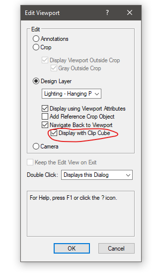
It can be done (as long as you're not hoping for a Hidden Line viewport...)! The way to do it is to set your Clip Cube and view in Design Layer space, then select the Clip Cube and run the View - Create Viewport command. Set the layer to the Sheet Layer and your options accordingly, then click OK. The viewport may be generated without the Clip Cube at first, but hitting the Update button in the OIP will set you right. You can edit the Clip Cube by double-clicking the Viewport and editing a Design Layer.
-
4
-
-
@The Hamma To be perfectly honest, I am not a fan of Resource Pop-up for a whole multitude of reasons (can't resize the window except from the right, so if your OIP is on the right as well as in the default workspace, you're kind of screwed; you can't add additional filters such as filtering for symbols containing attached records; and if you have a lot resources, it can be incredibly slow), so I don't use it in my own plug-ins. I much prefer to roll my own, and you'll find an example in the attached example plug-in in my first post on this topic. Feel free to copy the PopulateResourceArray procedure (builds arrays of Resource Manager folders and resources based on given type, you would just need to edit the initial BuildResourceList code at the top of the procedure to filter what you want), and the DrawDialog function and SymbolDialogHandler procedure to deal with the dialog.
Another, much more simple way to handle it would be to have your Symbol field be a pop-up parameter and to populate that pop-up during the kObjOnWidgetPrep event.
Actually, I added that exact functionality to the plug-in back in June. I've attached newest iteration of the example plug-in. You'll want to look at the kObjOnWidgetPrep event. Not as elegant as a symbol picker, but far simpler to code.
-
1
-
-
Quick note, do make sure that Enable Palette Docking is ticked on in the Session tab in Vectorworks Preferences. Afterward, you should be able to grab any palette and dock it to the top, bottom, or sides of the application window.
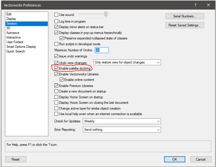
When I started with Vectorworks in 2010, all palettes were floating when working on Mac. I would throw them on a second monitor since you also couldn't auto-collapse the Resource Browser at the time (again, on Mac. You could certainly do it on Windows). I want to say that they added palette docking for Mac somewhere around VW2013.
-
2
-
-
Unfortunately, crops on Design Layer Viewports are treated as Screen Plane only, so in a 3D view it will show visibility based on the crop object in 2D space. No way around it unfortunately. My recommendation is to try to get use layer / class visibilities to limit the reference viewport or use a "blocker" object (solid white polygon with Pen set to "None" with a hole punched to show what you want to show) in conjunction with a Clip Cube to limit the 3D objects visible. I realize that this is less than ideal.
-
1
-


Sloped Floor
in Entertainment
Posted · Edited by Jesse Cogswell
@VIRTUALENVIRONS I understand that this might be a little out of your wheelhouse, but it is very common for the seating section closest to the stage (known as the "orchestra") to be bowled rather than stepped, particularly in "proscenium" style theaters (your example is a "thrust" theater, which I've only ever seen stepped). The seating structures that make up the "legs" are either shimmed or built to compensate for the slope (or "rake") of the floor. While I'm not familiar with the theater that @ticorules is referencing, based on the plan and section views they've provided and the nature of their question, I strongly suspect that the floor is indeed bowled. Usually the slope is relatively minor, my example above was exaggerated to better show the "bowl" shape.
Ordway Theater in Saint Paul, MN with a "bowled" orchestra: