Jesse Cogswell
-
Posts
632 -
Joined
-
Last visited
Content Type
Profiles
Forums
Events
Articles
Marionette
Store
Everything posted by Jesse Cogswell
-

ETC S4 Lustre series 3 symbols are not the right size or shape
Jesse Cogswell replied to DCLD's topic in Entertainment
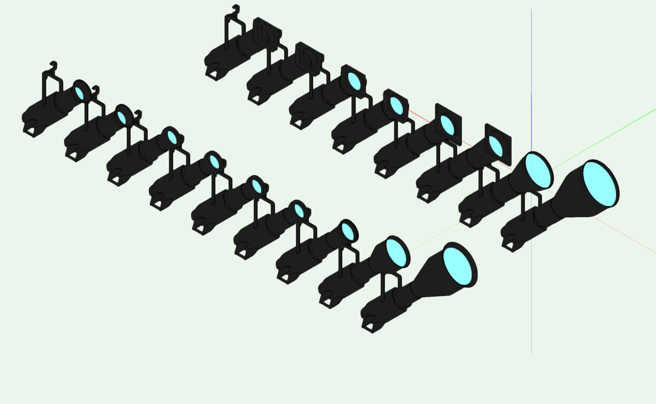
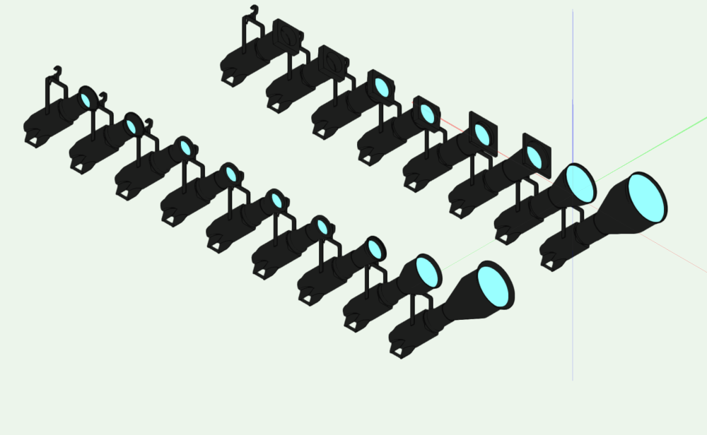
I had a couple of projects where I used Lustr Series 3 fixtures and needed accurate geometry, so I built my own off of the CAD files provided by ETC. A file containing them is attached (in VW2022 format, but I can backsave as necessary), it contains symbols for both the XDLT shutter barrels as well as the standard Source 4 / Source 4 EDLT shutter barrels. The EDLT tubes use the geometry from the standard VW library, but the XDLT tubes were all modeled from the ETC CAD files. ETC LED Series 3 Symbols.JNC v2022.vwx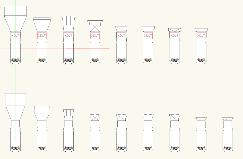
-
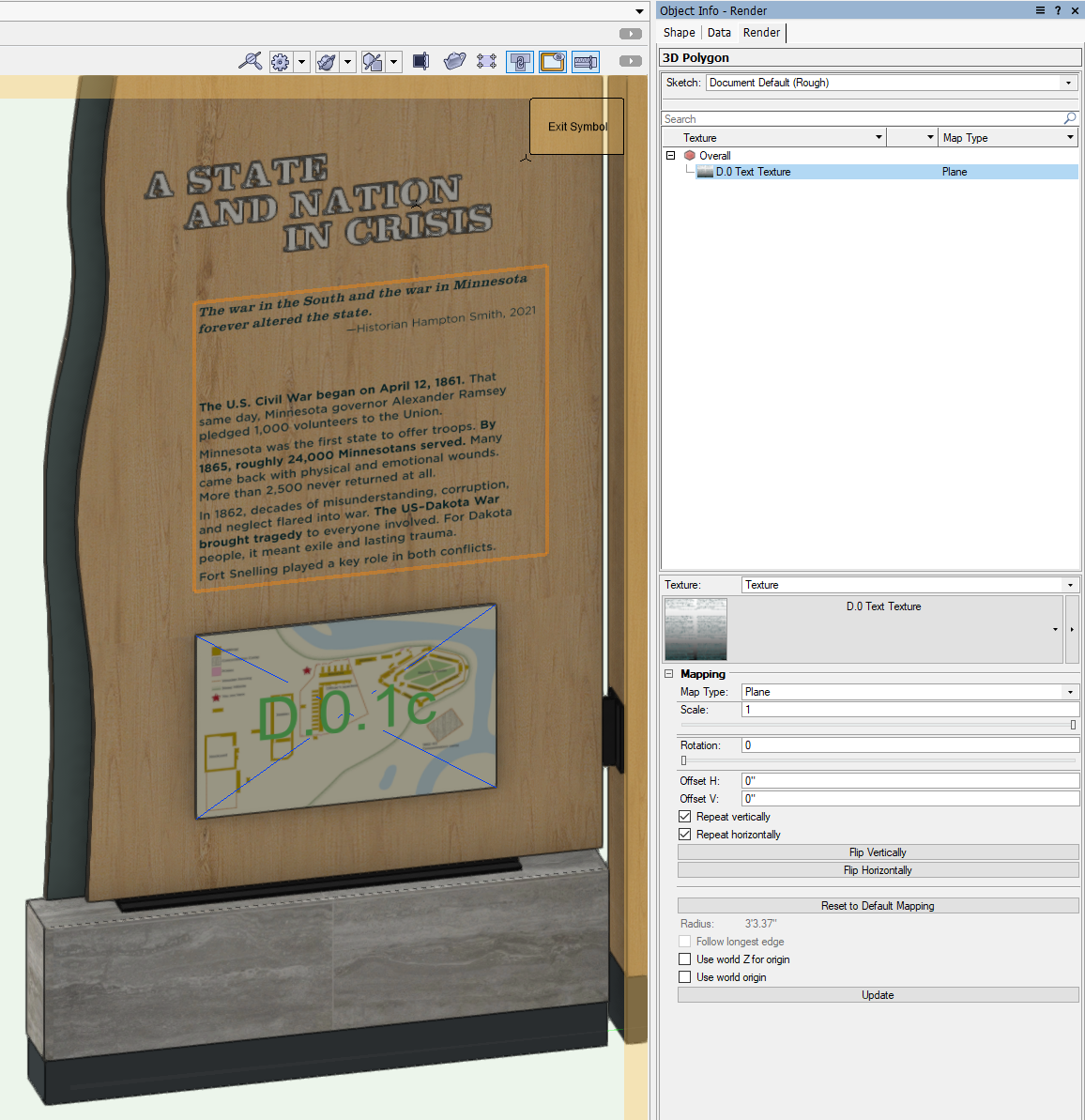
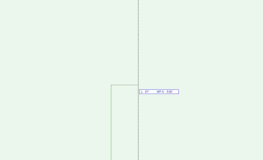
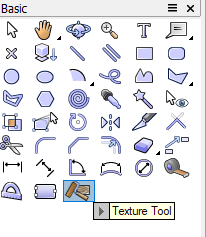
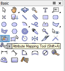
In your top screenshot, you'll see a "carrot" next to the texture "Asphalt Small RT". Click on the carrot to expand the texture part, which should reveal the decal. Something to consider is that decals can be very difficult to control when applied to the "Overall" texture part, so I recommend creating a Texture Override using the Texture Tool. Select the texture of the overall object (Asphalt Small RT in your example) and click on the face you want the decal to land on. This will add a "Face Override" in the texture tree in the Object Info Palette. Then select the Decal in the texture tree and use the Attribute Mapping Tool to position the decal. Texture Tool: Attribute Mapping Tool: Something to note, and it's the reason I very rarely use Decal textures, is that the Decal will not appear unless you are using a Renderworks or a Redshift render mode. So if you're sticking to Shaded, Decals might not be the best approach. What I would typically do instead is to create a 3D polygon with the size of the decal and apply the texture to that. You don't have to deal with attribute mapping and it is then visible in any rendering mode. The important thing to note about this is that the 3D poly needs to be moved slightly away from the surface (I usually do 0.01") so that the textures don't conflict. 3D Polygon Example: Wireframe View showing 0.01" Separation:


-
I have never used Project Sharing, but going through the documentation, could you use GetLayerProjectInfo to build a list of layers checked out by the current user?
-
Just did a test and deleting the source worksheet does indeed delete the worksheet image. @Sam Jones is correct in that you would need to pull the bounding box (GetBBox) and the original worksheet image scale (GetWSImageScaleF) then recreate the worksheet image using CreateWSImage and reapply the scale. You'll likely need to pull the original object's visual attributes as well.
-
You can select all of them and assign the universe and emissive settings, but as far as I know, there's no way to quickly assign the DMX addresses themselves.
-
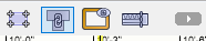
The other thing you can do is disable Auto Join Walls. This is normally found in the Edit tab of the Vectorworks Preferences window, but you can also add it to your shortcut bar in the upper right. This will let you grab the reshape handles of walls and move them around without them automatically joining. Shortcut Bar with Auto Join Walls engaged:
-
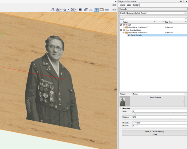
The Texture drop-down menu currently lists By Class. This means that it is trying to pull the Class Texture (set by opening the Organization window, editing the class, and specifying a texture within the Texture tab). Right now, the class your Extrude is in has no texture assigned, hence None being listed. Click on the drop-down and select Texture, this should add a texture picker to allow you to select a texture. See my screenshot above for an example. As for the decal, you must have a texture applied before you can add a Decal.
-
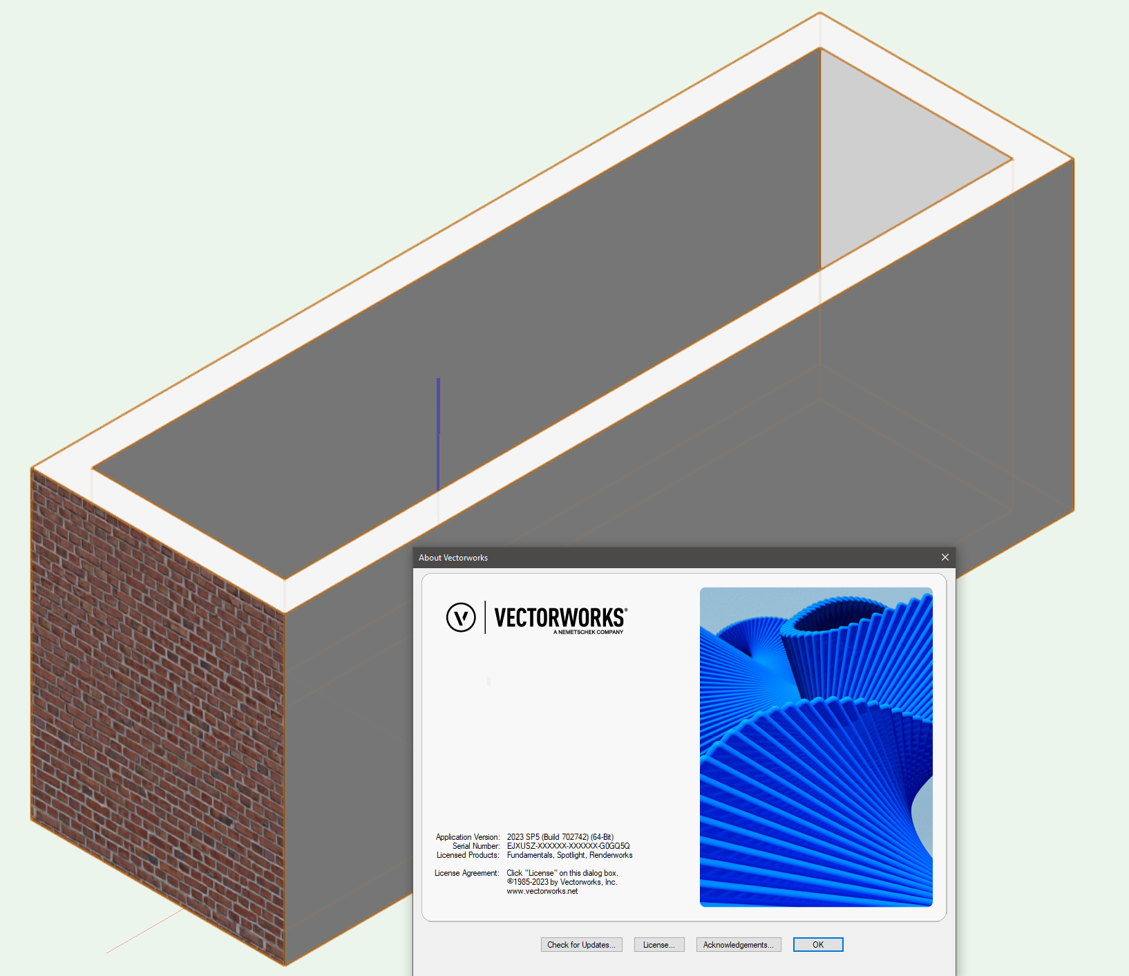
The issue you are running into is that Vision does not handle translucent textures at all. So things like glass (frosted or otherwise) don't translate and will come in as solid objects. There are two ways around this: You can make the texture on your cube more of a "scrim" texture, assigning a scrim style Alpha Texture to the cube object. It won't quite read as frosted glass, but you would get some glow from the fixture behind it. It's super not a great option, but could theoretically work. You can add a DMX controlled Emissive Mesh to the cube objects. To do this, select the cube and go to the Emissive section and expand it. You can set the Device Type to RGB and match the Universe and Channel to overlap with the RGB address of the corresponding ColorForce. You won't have the amber channel (can you get a ColorForce in RGBW?, I've only used them as RGBA), but then at least when you set your color in the console, the color should match the ColorForce color. It won't actually cast light since it is just an emissive, but it will get you close-ish, and if you load up on Bloom, it might give the appearance of casting light. I've put together a small demo showing this built in Vision 2023. It has five cubes, four set using the emissive method and one with the scrim texture. The emissive is undoubtedly the way you will want to go. It's not perfect, but it will give you an approximation. Cube Demo.mp4 Cube Demo.vsn
-
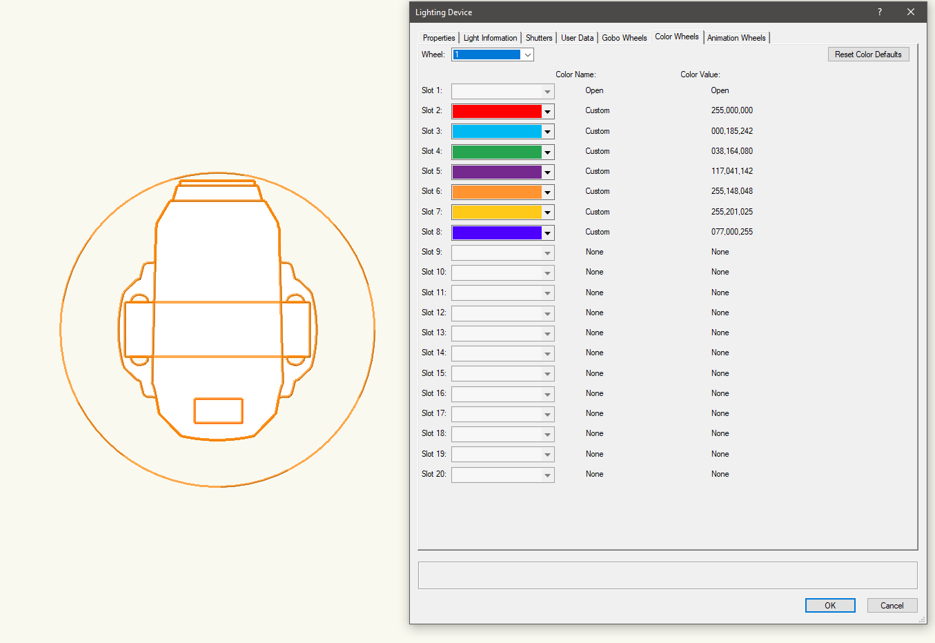
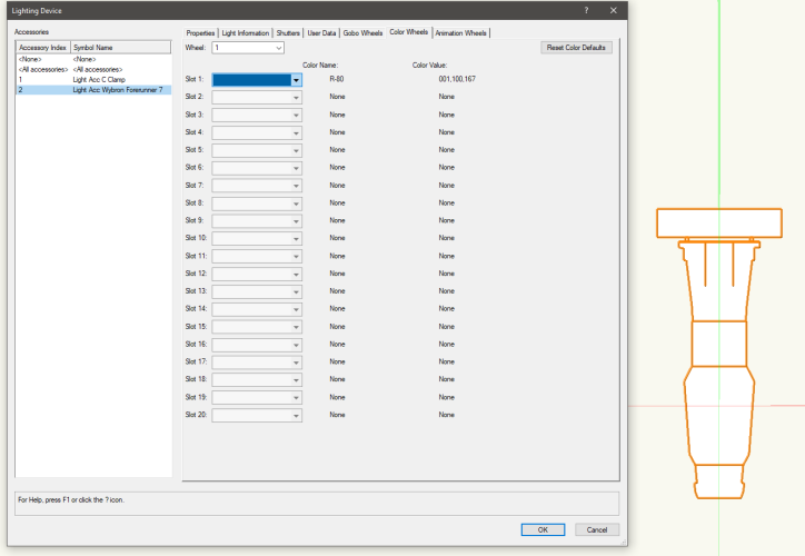
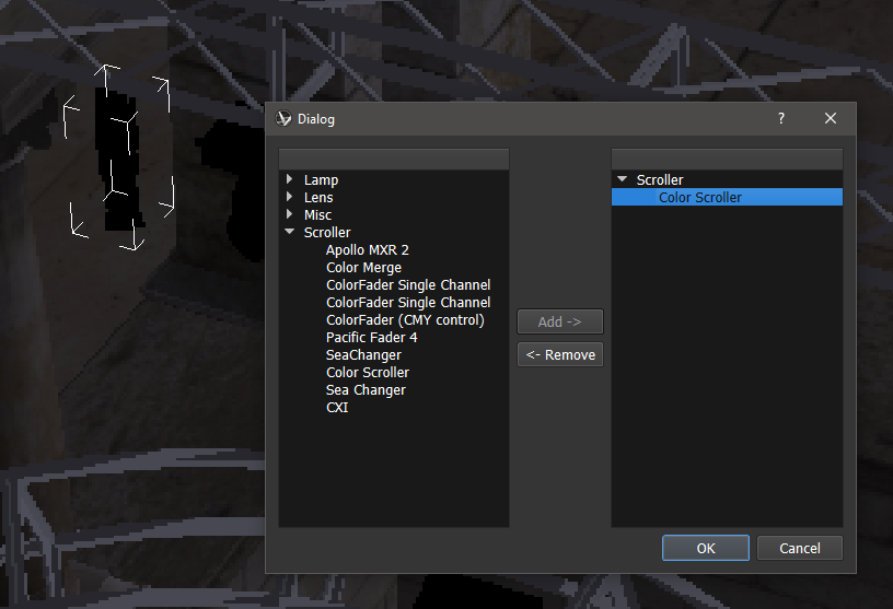
Color scrollers are a bit awkward in that neither VW nor Vision handle them particularly well. VW is great for putting them in as accessories and handling channeling and DMX addressing, but isn't really designed for doing more theatrical style renderings (setting different looks, etc), so there aren't too many options for setting scroller color. There technically is a tab in the lighting device editor for setting multiple colors per device that is supposed to carry over to Vision, but it doesn't work with scrollers. That's because that page only becomes active once you've assigned a Fixture Mode to the Lighting Device object, which is what Vision uses to set the personality when you make the export. Color Wheel editor in VW 2023 for a 14deg Source 4: What hurts us in this case is that a conventional that you would put a scroller on only has two slots to put color in, one slot on two different wheels, there are no personalities in Vision that cover scrollers. The Color Wheel editor is really designed for matching static color wheels in moving lights. These values will transfer over to Vision. Color Wheel editor for a Martin ERA 800: Before VW acquired Vision, back in the ESP Vision days, things like scrollers, I-Cues, VL500 lenses, and remote dimmer settings were handled in Vision through a process called Attachments. This was handled by a button called Manage Attachments at the bottom of the Properties window. Attachments Dialog as shown in Vision 2019: The problem is that in every version of Vision after being acquired, adding any kind of attachment to a light completely borked the light and converted it back to just basic geometry, losing the ability to control it. This broken "feature" was left in Vision 2017, 2018, and 2019 before being quietly removed in 2020. They did at least add I-Cues back in as a dedicated Lighting Device, but even then you don't really have controls regarding the lens tube beam degree or whether or not there's an iris. So in short, unfortunately you can't really use scrollers in either VW or Vision. If you need the scroll loaded in strictly for documentation purposes, Lightwright has you covered, but there's no way to simulate scrollers for renderings or visualization. It might be worth putting in a fixture request for adding your specific fixture/scroller combination to the library, but even then you'd be restricted to having your dimmer and scroller starting address being sequential since the remote dimmer channel in Vision would be handled by the now removed Attachments system.


-
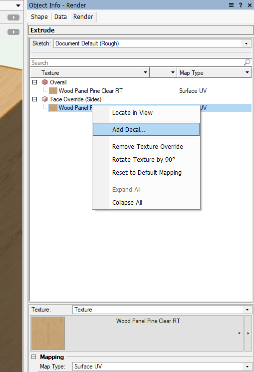
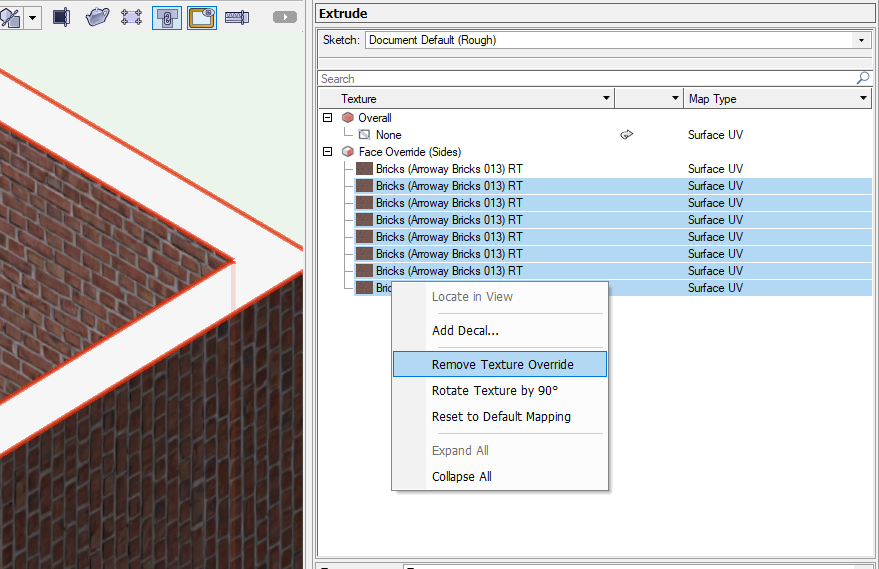
The Saved View that the presenter selected was a Saved View specific to his file, unless you are using the same file (it may have been supplied as part of a tutorial), you won't see the same options. You're likely seeing a void there because your drawing doesn't currently contain any Saved Views. What that Saved View did for the presenter was position the view to look at the surface he was using for the example, there's nothing the Saved View did required to set the decal texture. The video is out of date since they revamped textures in VW2022, but the process is largely the same as shown in the video. The one exception is that they removed the Add Decal button from the Render tab of the Object Info Palette and moved it to a right-click context menu. Select the component in the OIP you want to add a decal to and right-click it. Then select Add Decal from the right-click menu. The process should match the video from that point forward other than you can now build a face override using the Texture Tool rather than using Extract Face to build a new object. And you can totally paste screenshots into the forum. Just get the screenshot onto you clipboard by whatever means you want (I'm on Windows so I use Windows Key+Shift+S and drag a box), then paste it using Ctrl+V / Command+V into your post.
-
One way that I've done this is to use DelObject to delete the existing worksheet before creating the new one.
-
@Beat Per Light You should really look into the ForEachObject procedure. The script you are trying to write is VERY simple, with just two lines of "real" code (not BEGIN/END statements or procedure contructors). PROCEDURE SetDMXClass; PROCEDURE Execute(h:HANDLE); BEGIN SetClass(h,'003.Lightning-005.Cables-004 DMX'); END; BEGIN ForEachObject(Execute,(INSYMBOL & INVIEWPORT & (PST = 'Data XLR5-XLR5'))); END; Run(SetDMXClass);
-
TEXT ALONG CURVED PATH
Jesse Cogswell replied to DSmith2300's question in Wishlist - Feature and Content Requests
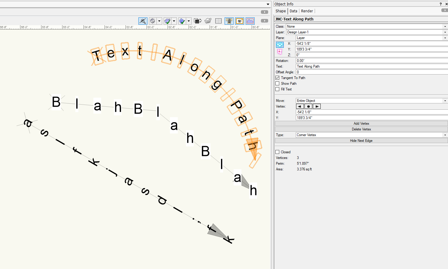
Because I can't leave well enough alone, I added a button to the Object Info Palette that lets you select a polyline, polygon, rectangle, oval, line, arc, or freehand object to serve as the path. There is a bit of weirdness when you use closed shapes like rectangles and ovals in that it doesn't treat itself as closed, since you would overlap the first and last letter that way. Just something to keep in mind. No real library, just standard Vectorscript. The code itself is relatively simple, the original plug-in was just 100 lines of code (including function descriptions and my standard comment header). The newer one with the button is 170 lines because of the added code for the event handling of the OIP button (event-based plug-ins add a lot of complexity even for relatively straightforward things). JNC-Text Along Path.vso -
TEXT ALONG CURVED PATH
Jesse Cogswell replied to DSmith2300's question in Wishlist - Feature and Content Requests
@DSmith2300 Give this tool a shot. It is a path-based Plug In Object that will parse a text string (entered in the Object Info Palette) along the path. There are options to rotate the text to the tangent of the path as well as an "offset angle." There are options to fill the text (though this might look a bit weird since the fill will be tight to each letter), and to show the path. The path, which has helpful markers showing the direction, will also show itself if the text string is empty. The path will be visible anytime the object is selected and can be changed later using the Reshape Tool like you would do with any other polyline or polygon. The tool will work on any version of Vectorworks newer than 2018. One quick note: if your path ends in a curve (as the selected one above), the last letter will be about 45degrees off, so you can put in a blank space at the end of the string to combat this, just draw your path with a little bit of overshoot. To install this, follow the directions below: Download the JNC-Text Along Path.vso file attached to this post. Navigate to your Vectorworks User Folder. The easiest way to get there is to launch the Vectorworks Preferences dialog, select the User Folder tab, and click on the Explore / Open in Finder button. Open up the Plug-ins folder. Place the downloaded .vso file into the Plug-ins folder. Restart Vectorworks. Go to Tools - Workspaces - Edit Current Workspace Click on the Tools tab. In the box on the left, find the JNC category and expand it. In the box on the right, find a toolset where you want the tool to live and expand it (such as Dims/Notes) Click and drag the JNC-Text Along Path tool from the box on the left to the target toolset in the box on the right. Click OK. High fives all around. Let me know if this tool fits your needs. SHORT EDIT: I should mention that the text settings such as font, style, and size are all set by selecting the object and using the Text menu bar. JNC-Text Along Path.vso
-
You can absolutely do this. The key here is to create an "empty" symbol (I usually use a 2D locus with a handle so I can delete it later), then use CreateDuplicateObject to duplicate the target PIO into the symbol container. Then you just need to set the Insert As Group object variable for the symbol. Below is a super simple way to do this in Vectorscript, you'll have to adapt it for Python. It will detect whether the selected object is a PIO, then ask a name for the symbol. If the symbol name doesn't conflict with an existing named object, the script will create a symbol in the Resource Manager root (you can add code of your own to determine placement), duplicate the PIO, delete the locus, and flip the Insert As Group flag. Easy-peasy. PROCEDURE ExportPIO; CONST kPIO = 86; kInsertAsGroup = 127; VAR h,pioHd,tempHd:HANDLE; symbolName:STRING; pt:POINT; BEGIN IF(GetTypeN(FSActLayer) = kPIO) THEN pioHd:=FSActLayer; IF(pioHD <> NIL) THEN BEGIN symbolName:=StrDialog('Enter symbol name',''); IF ((NOT DidCancel) & (GetObject(symbolName) = NIL)) THEN BEGIN GetSymLoc(pioHd,pt.x,pt.y); BeginSym(symbolName); Locus(0,0); tempHd:=LNewObj; EndSym; h:=CreateDuplicateObject(pioHd,GetObject(symbolName)); HMove(h,0 - pt.x,0 - pt.y); DelObject(tempHd); SetObjectVariableBoolean(GetObject(symbolName),kInsertAsGroup,TRUE); END; END; END; Run(ExportPIO);
-
I use SetPlanarRef(<handle>, 1) and then SetEntityMatrix to rotate the text.
-
For Each Object - Lighting Device Criteria
Jesse Cogswell replied to spettitt's topic in Python Scripting
Hmm. I just tried it in Vectorscript and it worked fine. I've never tried the PON= criteria, I usually use R IN ['Lighting Device']. I'm not terribly familiar with Python, but you might be having some trouble with your quotations. Try vs.ForEachObject(lightloop,('INSYMBOL & (PON = "Lighting Device")')). In VectorScript, you would need 'Lighting Device' to count as a string but PON = can be a direct command. Look at the syntax highlighting from the editor: When I ran this simple Python script, I got an accurate count of Lighting Device Objects: import vs counter = 0 def Execute(h): global counter counter+=1 vs.ForEachObject(Execute,("PON = 'Lighting Device'")) vs.AlrtDialog(vs.Num2Str(0,counter))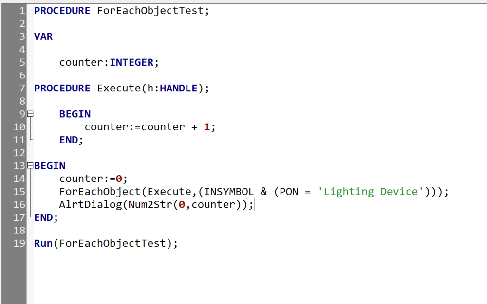
-
Are you talking about the Space object or is the ifc-space object you mention different? I do not have the full Designer suite, just Spotlight, so if it's a tool relegated to Architect or Designer, I won't be able to help you much. That said, I can imagine a menu command that works very similar to this tool that builds Viewports from Saved Views. After running the command, you would be presented with a list browser window with all Space objects listed with columns like Space Number, Space Name, Layer, Destination Sheet Layer (with an option to create sheet layers with a dialog to set sheet size and naming rules), VP Scale, and VP Name (with an option to auto generate based on the Space Name and Number). These columns would be sortable and there would be options to Select All, Select None, Invert Selection, etc. Upon clicking OK, the tool would go through each selected Space and create a Viewport using the current layer / class visibilities. These Viewports would use the Space's polygon as the crop object (with an option to include a "buffer" in case you wanted to extend the crop out a bit, but would still use the Space shape). One tricky thing is fitting the Viewport to fill a sheet layer. In past experiences with scripts generating Viewports, there's no way to ascertain the size of the complete Viewport until after the script completes, so it would have to be done as a separate command. This command, called something like Fit Viewports to Sheet Layers, would launch a list browser of all Sheet Layer Viewports sorted by VP Name but also sortable by Sheet Layer and similar selection buttons as mentioned above. When you click okay, it would determine the current VP size, the sheet layer size, and scale the VP to fit. If you wanted to find a scale from the more common scales, I would have to write a little bit to determine the largest possible scale while fitting on the Sheet Layer, and you would have to make a choice whether to use engineering or architectural scales. All of that is very doable, but I won't have time to actually work on it until mid-September.
-
Pass variables back into the PIO and update on changes?
Jesse Cogswell replied to karstenwolfGL's topic in Python Scripting
If you want to have static text as part of your OIP, you don't need to necessarily make your plug-in Event-Based. All you need to do is have a parameter with the Type set to Static Text. You then use a combination of vs.GetCustomObjectInfo to get a handle to the plug-in object, and vs.SetRField to update the parameter. My Python is SUPER rusty, I tend to develop in Vectorscript, but attached is a super simple example of a Point Object that updates its location in the OIP via a Static Text parameter. Simple Static Text Example.vso -
Texture Tool is no longer working in 2023 SP5
Jesse Cogswell replied to MGuilfoile's question in Troubleshooting
I'm still using SP5 and have no trouble with the tool. I'm also trying to understand what the specific issue you are having is, are you trying to get the apple image to only be applied on one face of the box? Even still, if the tool is somehow overriding the other faces with Apply to Face Mode active, couldn't you just remove the offending overrides through the object's Render tab? Isn't that easier than extracting faces or building new geometry? What about the Extract Face tool isn't working for you? It works as it always has for me. Textures don't cross over from the original object, but they never have, so to me it's not a busted feature (but may be worth a feature request if this is functionality that is important to you). If this happens to you again, could you please post a file? It would be helpful to identify if this is a problem with your Vectorworks installation or a bug within Vectorworks. I have seen weird behavior affect only a single Vectorworks file (usually one that has been converted from a different VW format through backsaving or opening an older drawing in a newer installation), but I've never seen the behavior you are describing with the texture tool.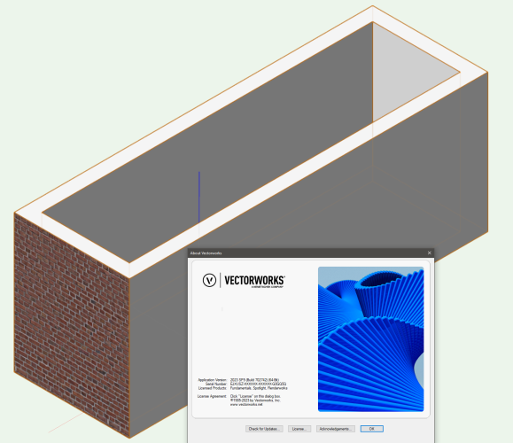
-
Cutting Complex Patterns Into Solids
Jesse Cogswell replied to Chame_liam's topic in General Discussion
Okay, those images help a lot. The way I would approach it is very much the method I describe above with some key notes: Each hole / aperture shape MUST be a single closed polyline. Use the Compose command to make them such if they are not already You can select an entire face's worth of hole shapes and extrude them all at once. This is something that typically makes VW very grumpy, and may be what is leading to some of your issues when doing a Subtract Solids operation. HOWEVER, if you select the Extrude and Ungroup it, it will instead turn into a bunch of extrudes, each with a single polyline. With this in mind, I would do each face as an extrude, either on the face directly using the Set Working Plane tool or by extruding in Top/Plan and rotating the resulting extrudes in place. Once all six faces are placed, I would grab the six Extrude hole objects and ungroup them all at once, resulting in dozens of extrudes. From there, add the pillar to the selection and run the Model - Subtract Solids command. This should result in your more or less finished pillar. When using either Subtract Solids or Add Solids, you want to stay with as few steps as possible. Every time you do one of these operations, it adds a step to the final object's "history." There is nothing in VW that will make your file size huge and your drawing choppy than having a bunch of objects with really complicated histories. It also becomes really hard to edit since you have Solid Subtraction nested inside Solid Subtraction nested inside Solid Subtraction, it's best to do it in a single step. Once you are satisfied, you can then run Modify - Convert to Generic Solid to remove all of the object history. This will make the file size smaller and the drawing snappier, but you will no longer be able to edit the shape, so it's best to do it at the very end and save a backup from before converting just in case. I'm tapped out for tonight, but if you post a partial file with one of the DWG pillar cutouts, I will attempt to fab one up in the morning. -
Cutting Complex Patterns Into Solids
Jesse Cogswell replied to Chame_liam's topic in General Discussion
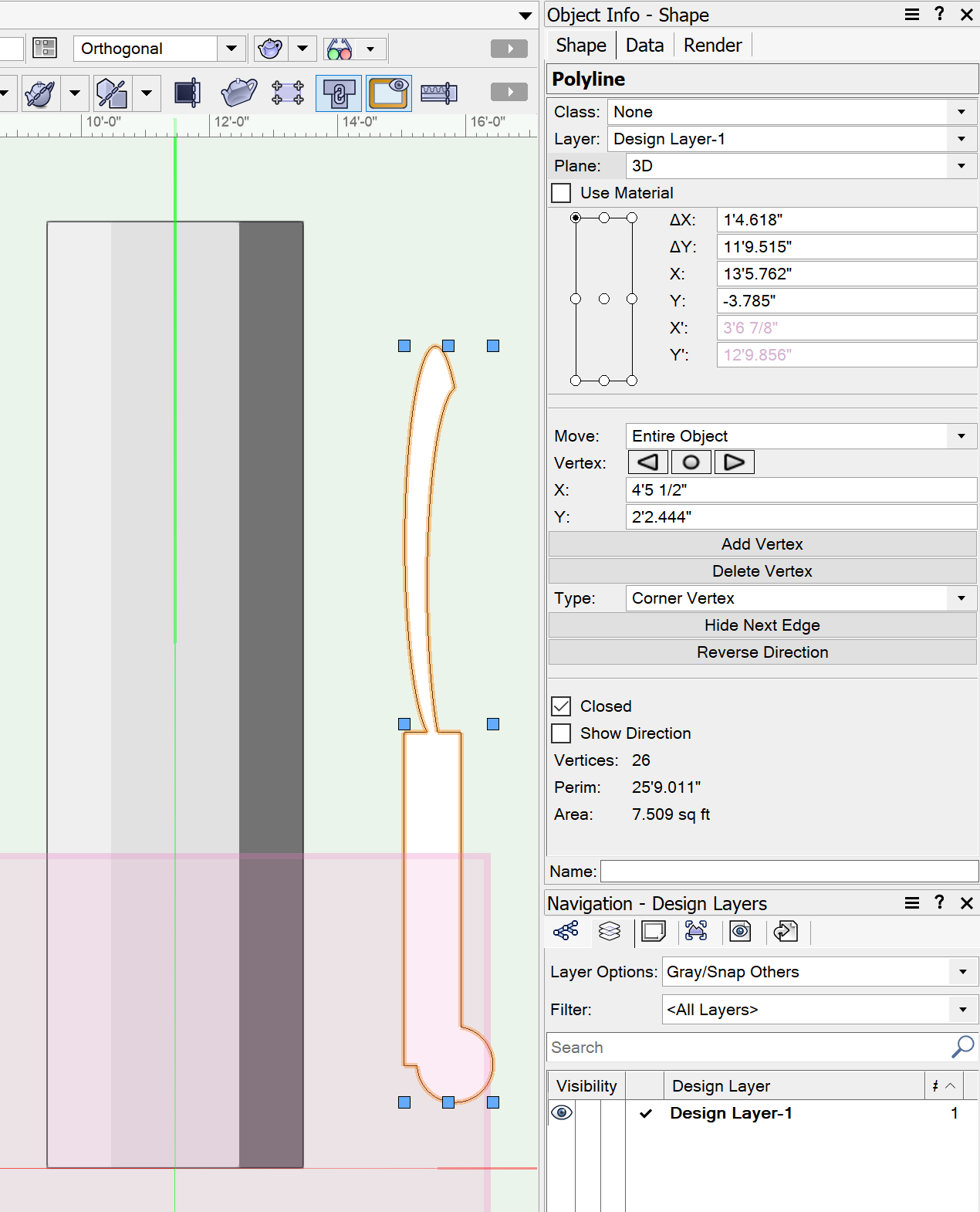
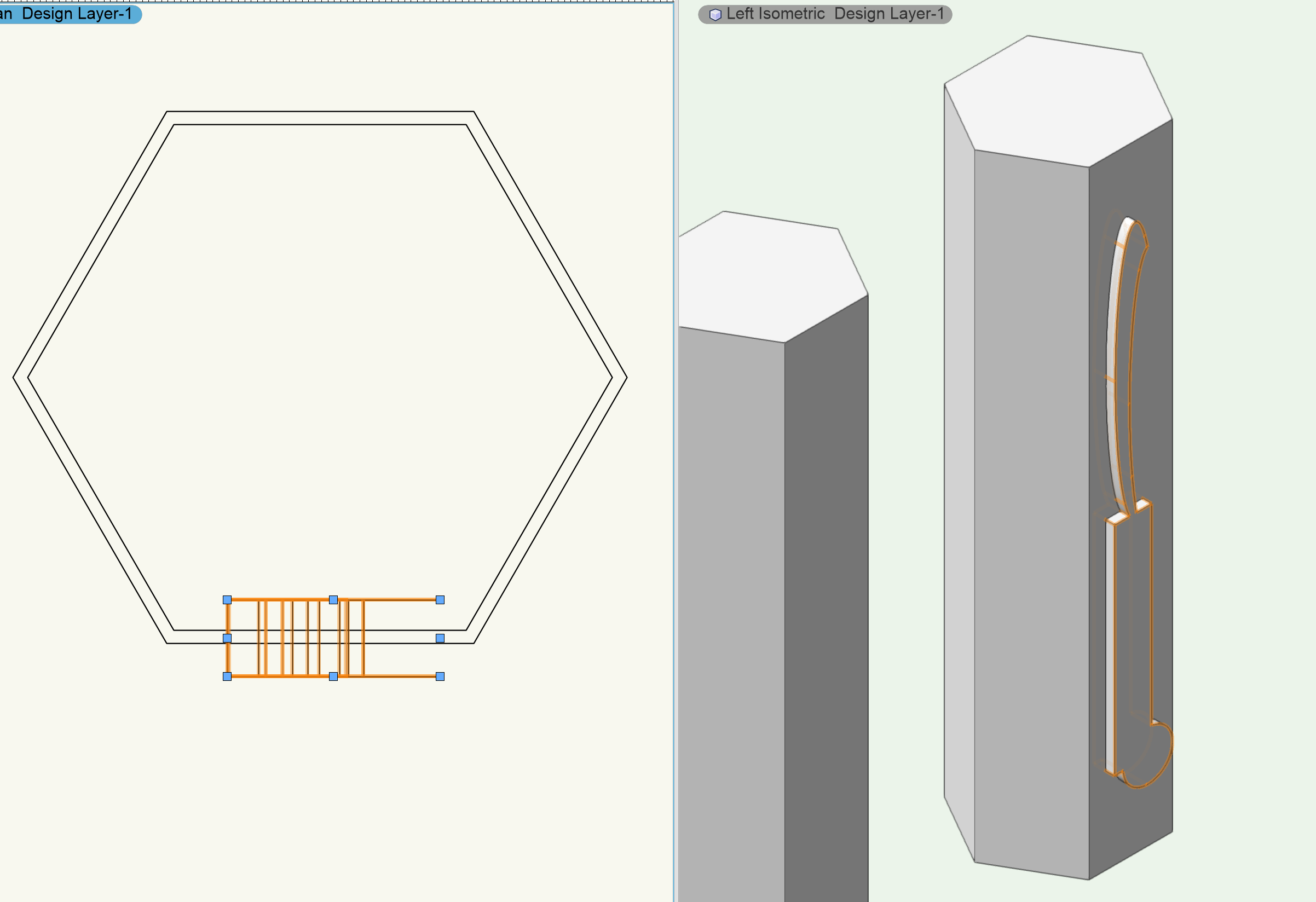
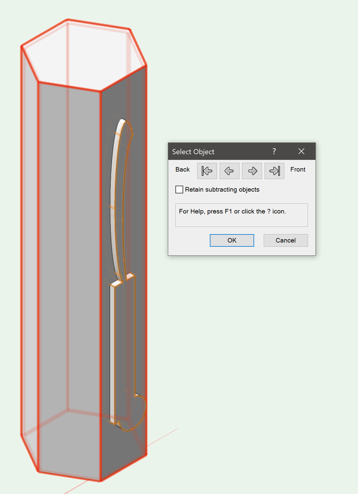
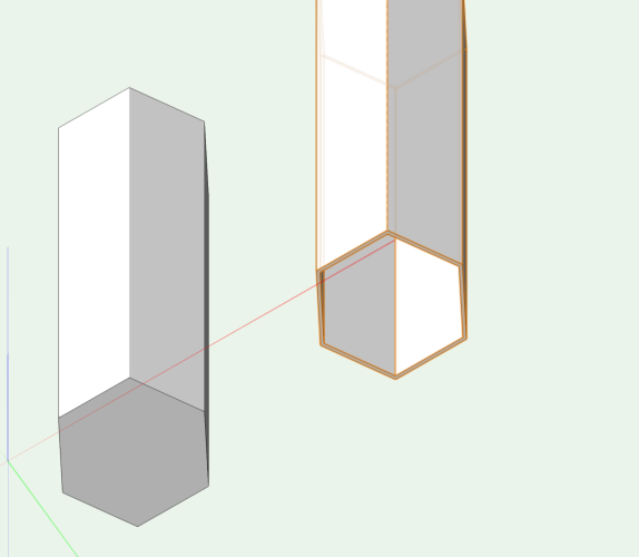
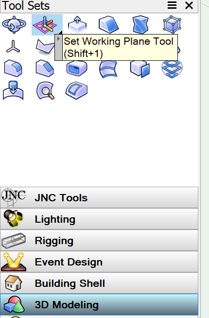
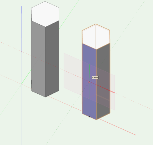
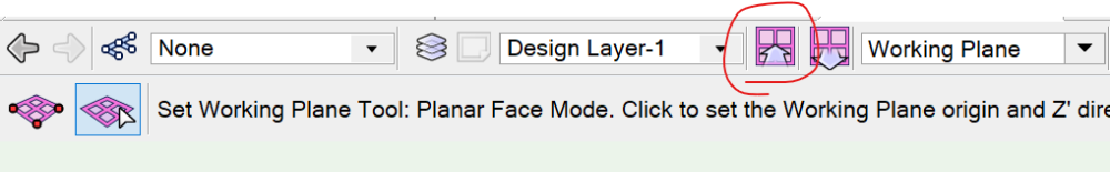
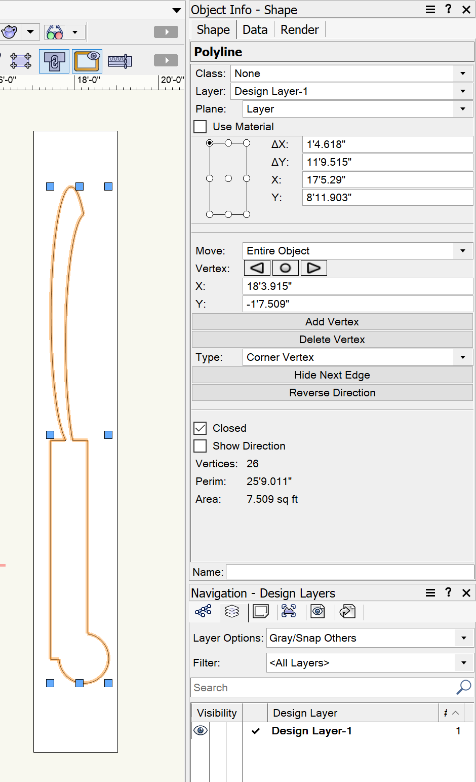
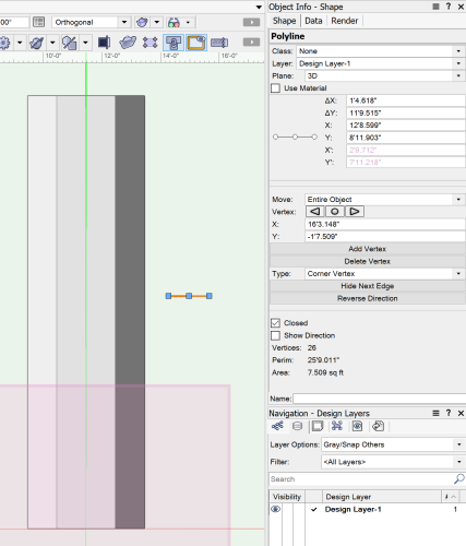
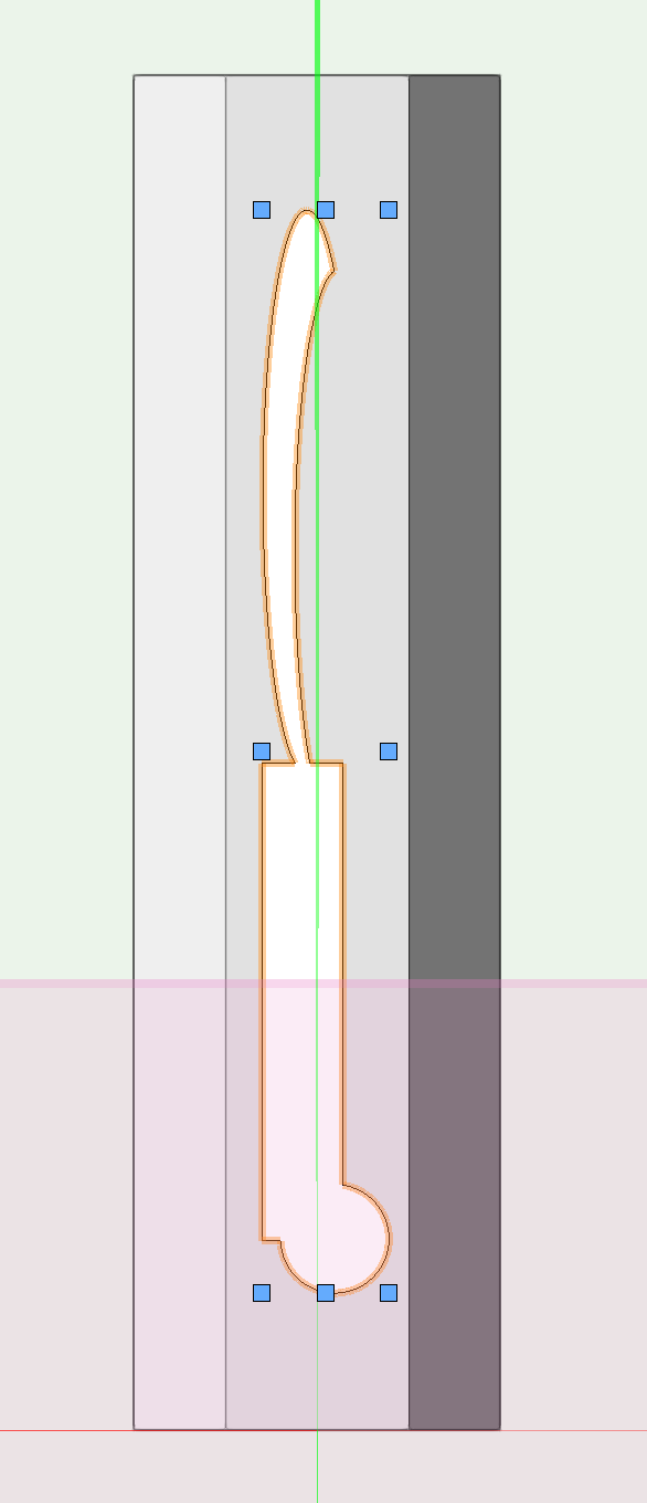
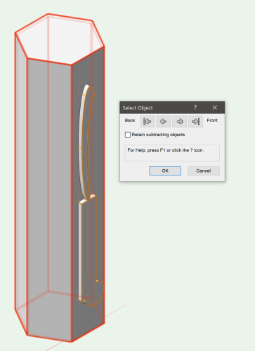
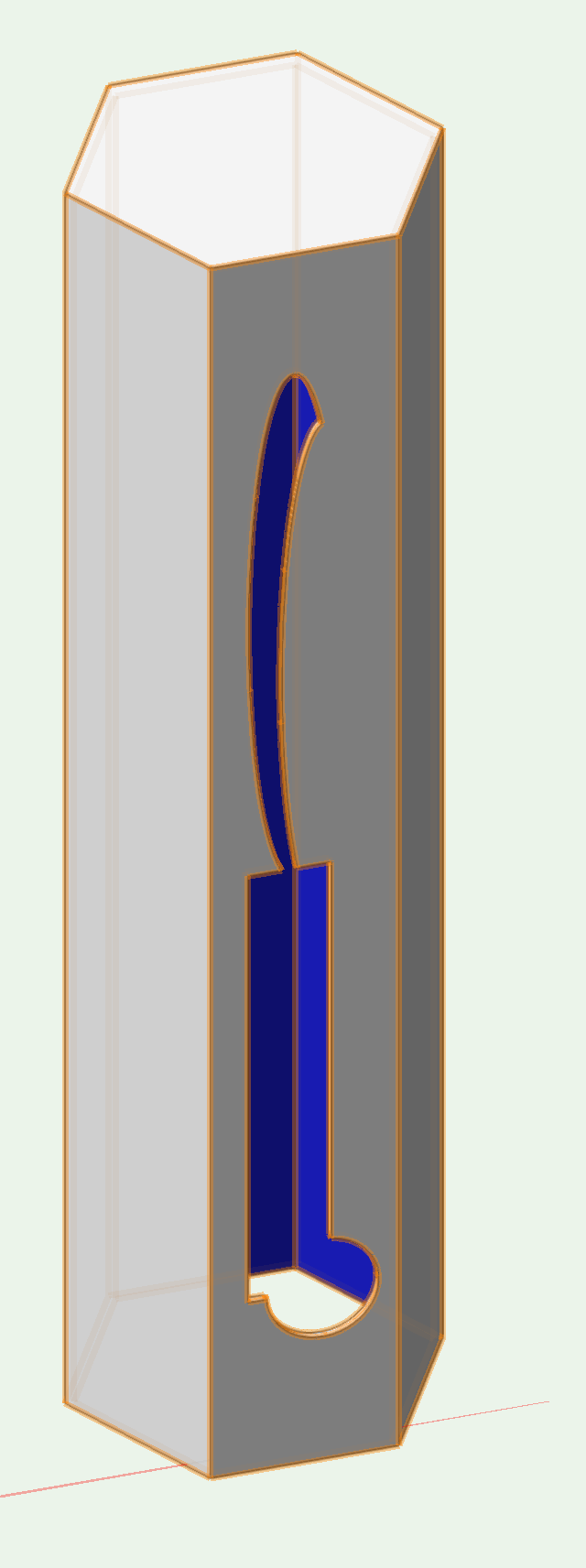
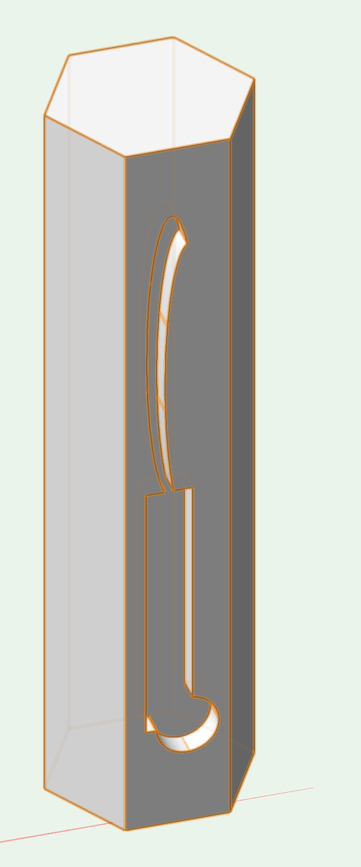
I think a couple images would go a long way to helping me understand what you are looking for. Are the hexagonal pillars "shells" with the patterns cut into each of the six faces? Or are the pillars solid with the shapes cut in recess? Getting the shapes into the faces are going to be roughly the same process regardless, but if you want the shapes to punch all the way through each face, then you will need the pillars to be shells. Luckily, there is a tool that will do this for you, the Shell Solid Tool found in the 3D Modeling toolset. This tool allows us to select a solid, specify a thickness, and select an open face. Two hexagonal pillars, standard Extrude on left, Shell on right with open bottom face and 1" thickness In terms of getting your shape onto a particular face of the pillar, you could try using the Set Working Plane tool, which will allow you to select a face to be your Working Plane. Selecting a face: From here, we can use the Look at Working Plane button to set the view looking directly at the selected face. Any 2D shape we draw from this view will now be directly on the chosen face of the hexagonal pillar. Either we can manually draw a shape, or we can copy and paste from the flat DWG file. What's most important in this step is that the shape needs to be a single closed polyline / polygon object, not a combination of lines, arcs, and polylines, as AutoCAD sometimes wants to break them up. If the shape is constituted of multiple lines / objects, select all of them and run Modify - Compose to turn them into a single shape. Then just make sure that the Closed checkbox is checked in the Object Info Palette. We can Copy said object from the standard Top/Plan view, then set our view to a face using the method above, and then Paste. When you do this, the shape will come in flat to the floor, so change the Plane drop-down in the OIP to Working Plane and position the shape accordingly. 2D Shape in Top/Plan View: Initial Paste: After Working Plane selected in OIP: Shape positioned on object: From here you can extrude the shape. A negative value will punch the shape toward the inside of the pillar, a positive will bring it out from the pillar. It's up to you which one you want, but in my experience, you really want to make sure that if you want a full hole, you want the extrude to poke out a bit from each side. From here, select both the pillar and the shape, and run Model - Subtract Solids. The "main" solid will be highlighted in red, make sure it's the pillar. You should now have a hole in your pillar. If each of the six faces have these kinds of shapes, make all of your shape extrudes, one for each face, then select all of them and subtract them in one step. Hole punched, inside of Pillar textured in blue for clarity: If you are needing to have the shape "recessed" into a solid pillar, the steps are largely the same except you will want to make sure that your extrude is set to the proper depth. Shape recessed 6" into pillar face: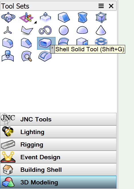


-
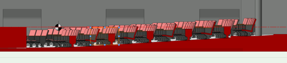
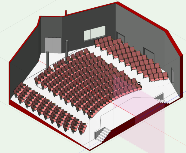
The way I typically approach it is to build a row of seats as a group, then use the clip cube to limit the view to the center of the bowl on one side. I then go into an orthographic side view with a Shaded render and move the row until it contacts the bottom of the bowl. I usually build a Saved View to quickly get back to this. Here's an example from a small theater that I drafted a couple of years ago: Capri Theater CL Section Right Rear Isometric of house floor: I created the floor using the first example (extrude along path) mentioned above, but would probably try to do it with the NURBS method if I were to attempt it today. You'll see at the back of the house where the bowl transitions to a flat floor that there is a little bit of a gap. I think the NURBS way of tackling this might produce a cleaner transition, though it might also be too much for Vectorworks to handle. EDIT: All that being said, it does take a bit to get the curve of the seating to match the curve of the floor. At the Capri, I made sure that the seating row arc used the same center point as the front arc making up the bowl. In @ticorules's example, you wouldn't necessarily be able to do that since the seating rows have a much more shallow arc than the bowl does, without having a copy of the drawing, I suspect I would work to try to get it as close as possible, then match the height based on centerline and hope for the best. As for the seats, I don't usually worry too much about the "legs" meeting the floor in a 100% accurate fashion (the ones in this example are drawn flat, slightly protruding into the floor on the downstage end). What's important is making sure that the seat bottoms are accurate so that you can surmise where an average audience member's head will be to calculate sight lines. If someone is fixated on the seating not cleanly meeting the floor in your rendering, then you probably have far more worrisome problems happening with your scenery...
-
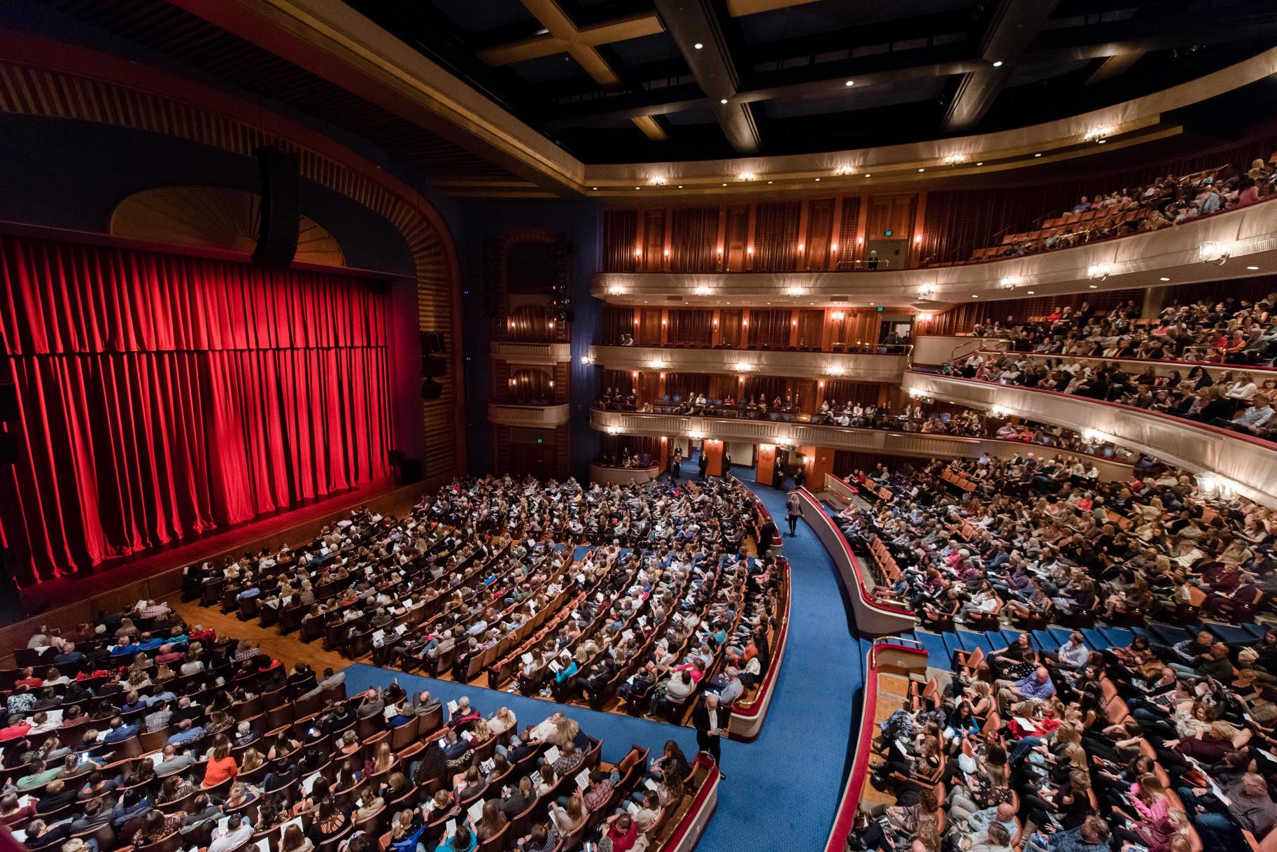
@VIRTUALENVIRONS I understand that this might be a little out of your wheelhouse, but it is very common for the seating section closest to the stage (known as the "orchestra") to be bowled rather than stepped, particularly in "proscenium" style theaters (your example is a "thrust" theater, which I've only ever seen stepped). The seating structures that make up the "legs" are either shimmed or built to compensate for the slope (or "rake") of the floor. While I'm not familiar with the theater that @ticorules is referencing, based on the plan and section views they've provided and the nature of their question, I strongly suspect that the floor is indeed bowled. Usually the slope is relatively minor, my example above was exaggerated to better show the "bowl" shape. Ordway Theater in Saint Paul, MN with a "bowled" orchestra:

-
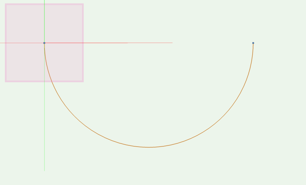
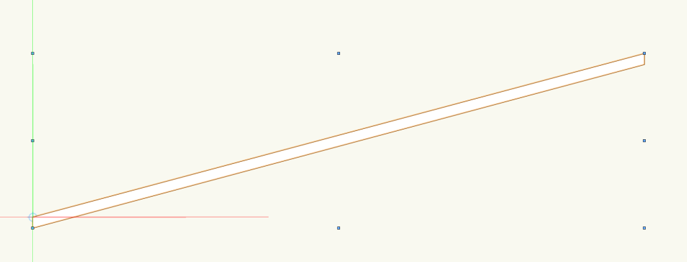
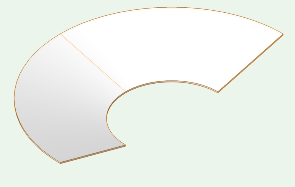
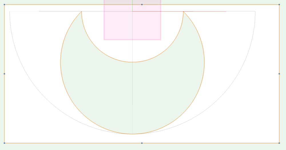
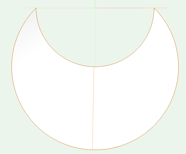
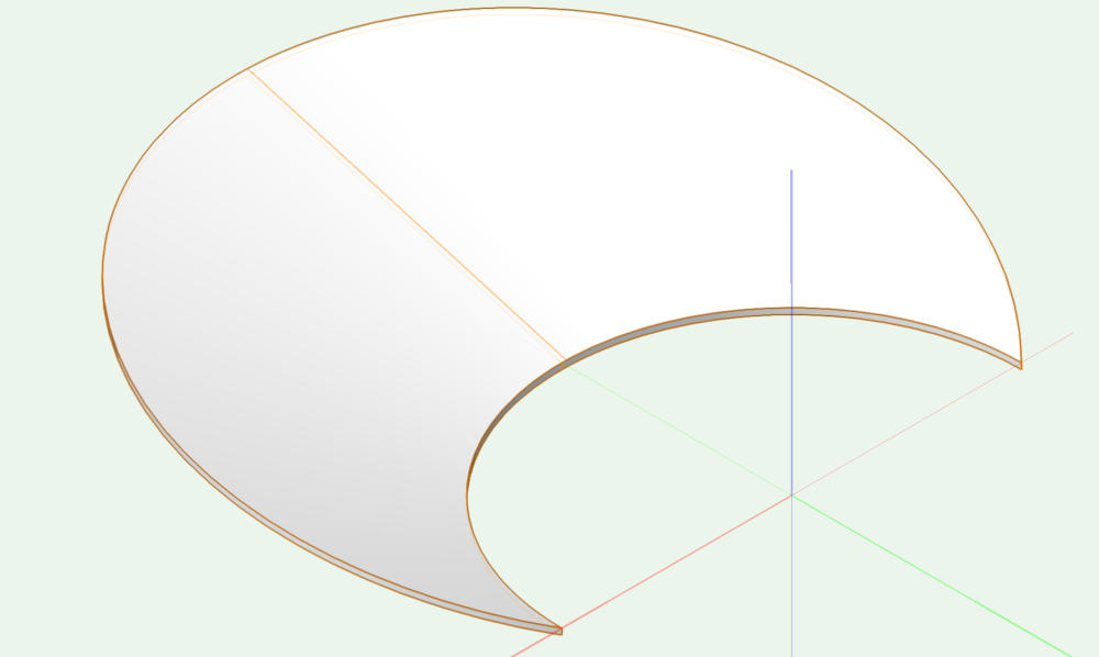
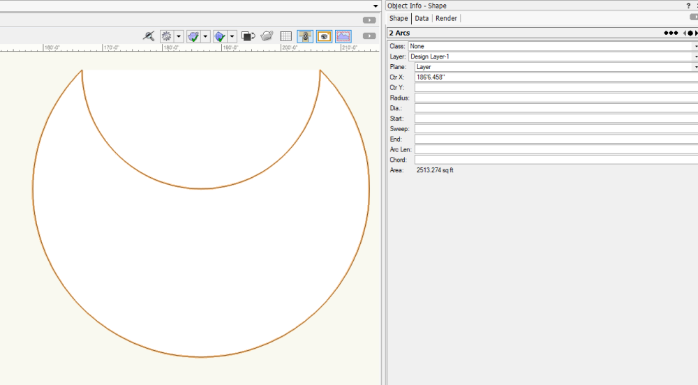
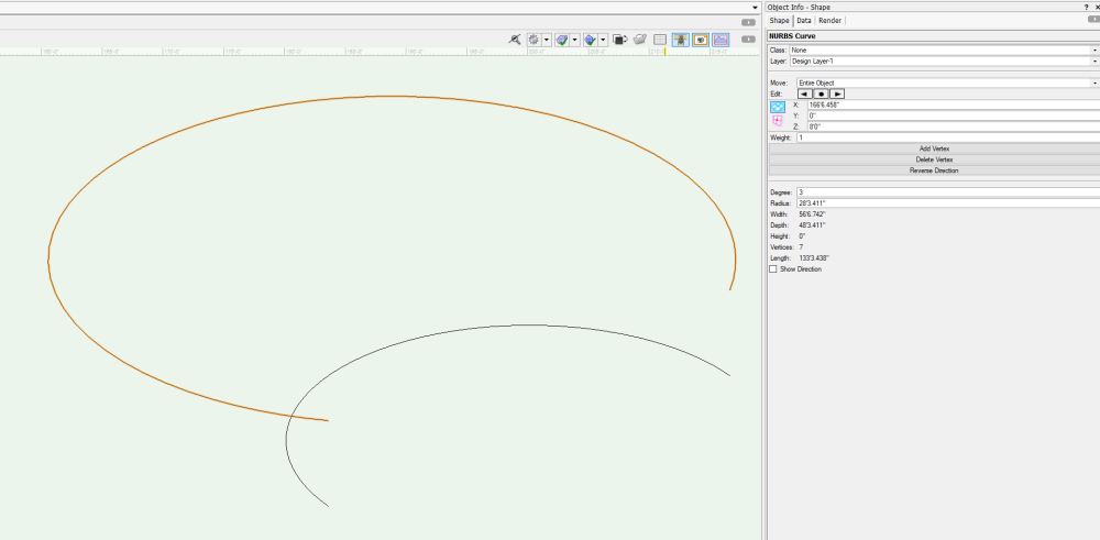
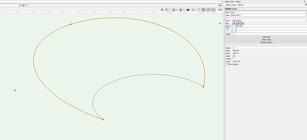
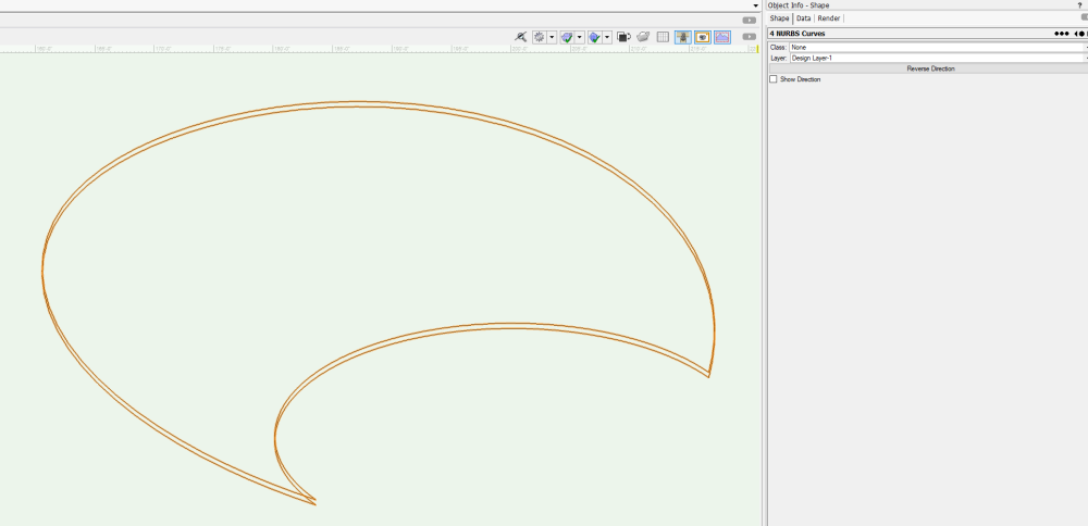
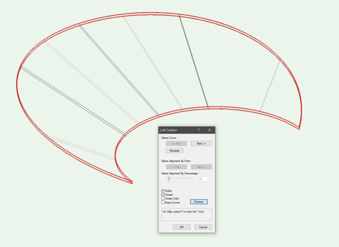
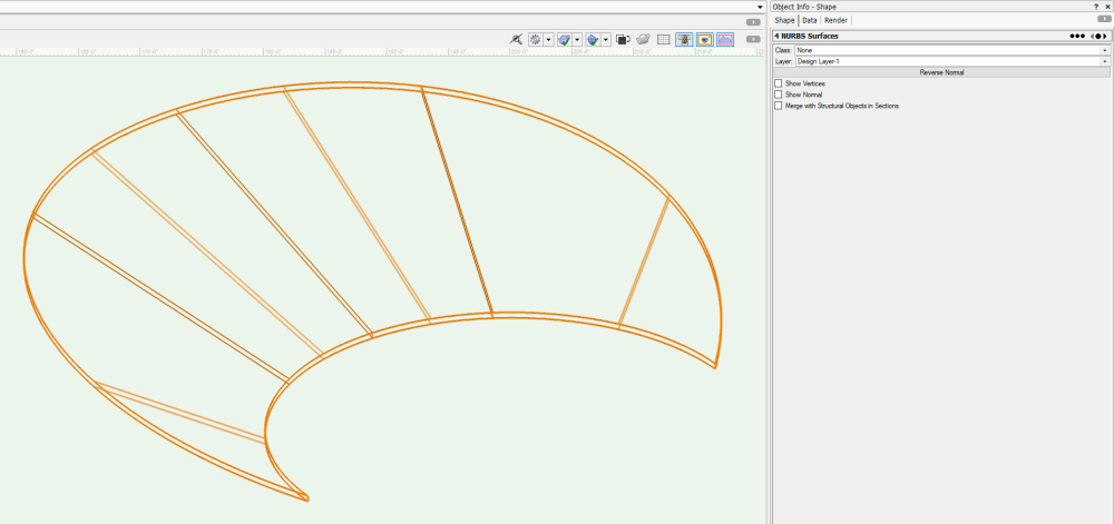
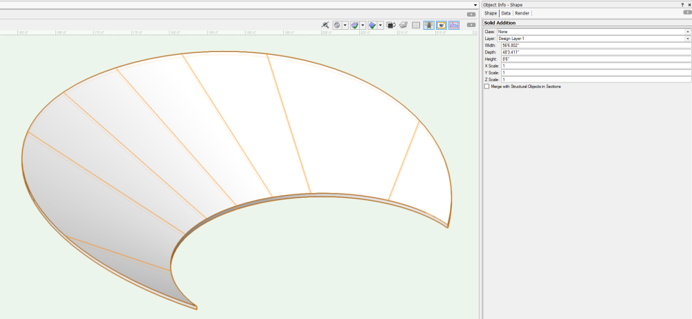
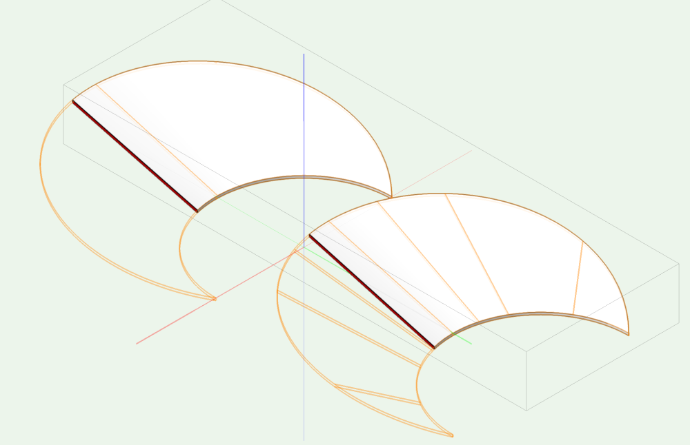
There's a pretty easy way to create a "bowl" shape in this instance that I've used in the past for orchestra floors using Extrude Along Path and Subtract Solid, though I've never encountered a bowl shape going into a curved house wall, so this method might not get accurate results on the edges: Path matching US side of orchestra floor ("Bowl"): Profile matching house rake and floor thickness (6" in this case): Extrude Along Path Result: Creating Polyline for Extrude for Subtraction: Final Shape Top View: Final Shape Right Rear Isometric: There is another way to do this using NURBS that could also work (and might be a bit more accurate): Two Arcs representing each curve: DS NURBS Curve set to Z height of back of house (8'-0" in this example): DS NURBS Curve edited so that US points match with lower NURBS NURBS Curves Ctrl+click-and-drag 6" lower to duplicate, ending with 4 NURBS Curves: Loft Surface Tool in No Rail Mode, selecting 4 NURBS Curves: Ungrouping Revealing 4 NURBS Surfaces: Creating Solid by using Model - Add Solids: Both methods produce "Water-tight" solids, good for Section Viewports: