Jesse Cogswell
-
Posts
634 -
Joined
-
Last visited
Content Type
Profiles
Forums
Events
Articles
Marionette
Store
Everything posted by Jesse Cogswell
-
It might be something tied to Windows. Here's what my view bar looks like in Regular Mode: And here's in Compact Mode: All of the drop-down menus are extremely short and can't currently be resized. This makes compact mode next to useless for me.
-
I think this is a really tough topic that Vectorworks has to deal with. Every user has an opinion about it, and none of them match. Any change made in any direction is going to upset a number of users. There was a massive thread that got started back in 2017 that sparked a huge discussion of what the GUI of Vectorworks should and should not be, with the original post being about how Vectorworks should not have any color in it's interface since it distracted from the design being worked on: This is a terrific thread to look through since it shows what users have been interested in over the past six years. Even back then, we were discussing how old VW feels in terms of UI, and not just icons. A lot of operations take more clicks than they really should, and the modal nature of VW means that if a dialog box is open, nothing can be done until that dialog is closed, which makes VW feel really dated. Personally, I like a lot of the new interface and it feels like a move in the right direction. I have some nitpicks about the new View Bar (compact view makes the class and layer drop-down menus too small, so you can't see what the active class and layer are, the Organization menu is now buried so that it takes two clicks to get to), and while I agree that they might have gone a touch too far in removing tool icon colors, the move to using SVG icon files is a really smart one. I also agree with @Tom W. that some of the new Quick Preference icons don't make a lick of sense and it forced me to change my Windows accent color just to even be able to see them.
- 99 replies
-
- 5
-

-
- vectorworks 2024
- new ui
- (and 1 more)
-
@FranAJA Unfortunately, my Python is more than a little rusty. I learned Python back in 2010 and wrote some pretty handy little programs in it, but haven't touched it since. I learned Vectorscript a year later in 2011 and rather enjoy the strictness and structure of it. Since they added Python in as an option in 2014, relearning Python has been on My List of Things to Do™, but that list is very long and only gets longer by the day. I find that the Python implementation in VW is a little sloppy, as it forces Python to behave like Pascal and thereby negates a lot of the benefits of Python. I really haven't been able to wrap my head around variable handling and tuples and the level of documentation and examples is slim (it took me ages to figure out how to make GetCustomObjectInfo to work in Python, and I still don't fully understand it). My current practice is to do as much in Vectorscript as possible, then use PythonBeginContext, PythonEndContext, and PythonExecute to use Python's extensive libraries for things that aren't covered by Vectorscript. That all being said, I can help as much as I am able. One nice thing about the VW Python implementation is that all of the functions are basically the same, just with a vs. prefix added to them and returns being handled with tuples instead of constructor arguments, so the biggest hurdle when translating my example is just reworking a bit of the syntax. The example I have linked above is designed to demonstrate three different, and all fairly complicated, concepts: Event-Enabled plug-ins, dialog handling, and building resource and parent arrays for dialogs. What are you trying to implement into your PIO? If you're looking to implement both things, my recommendation is to work on one thing at a time. Start with getting an Event-Enabled plug-in working. Something simple like a point object that uses CreateText to put a string parameter on the drawing, and a button in the OIP that launches StrDialog to change that string parameter. You should be able to follow a similar structure to what I have in the Vectorscript example starting with the vsoGetEventInfo function, substituting an if/elif structure for the CASE statement. Each line in the driver of my example is commented to explain exactly what the code is doing, so it should be pretty simple to translate it into Python. Dialog handling in Vectorworks is a whole other thing, and something you can practice in a document script outside of a PIO. Generally, VW requires two different functions for each dialog, a builder and a handler. The builder (DrawDialog in my example), creates and arranges all of the elements that make up the dialog. I always approach this in the same way: Create all elements starting with static text objects, then moving on to interactive (text fields, buttons, checkboxes, etc), then to groups. What's important to note is that VW will use the element ID order to determine the order when using the Tab key to navigate the dialog, so I try to make sure that I number and create things in the order that I imagine the user will want to interact with them (usually top to bottom). The other important thing to note is that the OK button will always be element ID 1, and the Cancel button will always be element ID 2, so it's best to start numbering your elements at 11. I usually make my groups start at element ID 101, but didn't in the above example for some reason. Set group items. This uses SetFirstGroupItem to set the first element, then SetBelowItem or SetRightItem to position elements from there. I generally populate one row at a time, so using SetRightItem to position elements for the row, then SetBelowItem with the first element from the last row as the first argument to start setting the next row. Set layout items. I usually try to group a lot of elements, so for me this is mostly setting my groups into the dialog. Same format as setting group items except you'll use SetFirstLayoutItem to set the first element. Align items. This uses AlignItemEdge to line things up to make them look nice. I use this to make text boxes line up with pop-up menus and make group boxes all line up. If you get clever with your element numbering, you can use a FOR statement to do a whole bunch of elements at the same time. One thing to note is that this doesn't really work with Static Text elements, so it's best to make all of your static text the same length by passing in the length of the longest text string as the widthInCharacters argument for all the static text. Add help strings. Using SetHelpText, add help text for each element that needs it. I do this in all of my plug-ins outside of very simple and self-explanatory dialogs, or when I'm feeling lazy and the plug-in is strictly for a forum example. Once you've created your dialog, you'll need a handler callback function to deal with it so that you can use RunLayoutDialog. This will use an if/elif structure in your case to handle interactions with any dialog elements. The RunLayoutDialog page of the online function reference has a decent Python example of how all of this works, but it's missing some things in the handler that are handy to know: If you need to populate or preset any dialog elements, you will need a SetupDialogC item and this will likely want to be the first thing in your if/elif structure. I'm unclear if vs.SetupDialogC works on its own or if you will need to define a constant as kSetupDialogC = 12255 as shown in this thread. As in the function reference example, item == 1 is what happens when you press the OK button. This should pull values from the dialog and update global variables or change drawing elements as needed. item == 2 is what happens when you press the Cancel button. I'll always put this in the code, but often leave it blank. If my dialog updates global variables and executes things in the driver, I will usually put in a global boolean check that the Cancel button sets to FALSE. item == X, where X equals the dialog element ID that you defined in the builder. This is where you can set buttons in the dialog to populate elements within the dialog. In my example, I have code that will update the Symbol Display Control when you interact with the Thumbnail Popup. In Python, this would read as elif item == 31: Again, I would practice building a dialog in a document script and get the general concepts and structure down. Now, building arrays of resources and parents for populating the thumbnail popups will be the toughest thing to translate from Vectorscript to Python. The way Vectorscript handles arrays is very rigid and restrictive, so my PopulateResourceArray procedure has to do some pretty dodgy things to build my resource array. It's a 2D array, with the X being the parent (folder name in my example) and the Y being the resource name (symbol or texture name). So it's constantly resizing the Y size of the array if the number of resources in a parent would exceed the bounds of the array. Python is far better than Pascal with dealing with data in this way. There's probably a clever way to use the Python Dictionary structure that can make this whole process much more simple, but I would need to noodle around with Python a bit before I can really help you with this process. My schedule is more open next week, so if I find my self with some time, I might try to adapt the example to Python, but I can't really make any promises. Again, any interactions between the code and Vectorworks will largely be the same between Vectorscript and Python, so a lot of adapting my example code is just translating the return syntax to fit Python. The biggest things to know in terms of structural differences between Python and Vectorscript is that all variables and constants in VS must be declared before they are used and be declared in a specific "block". This is obviously not the case in Python. More information about the "block" structure of Vectorscript can be found in this thread: This might help in navigating the overall structure of my example so that you can translate the structure to Python.
-
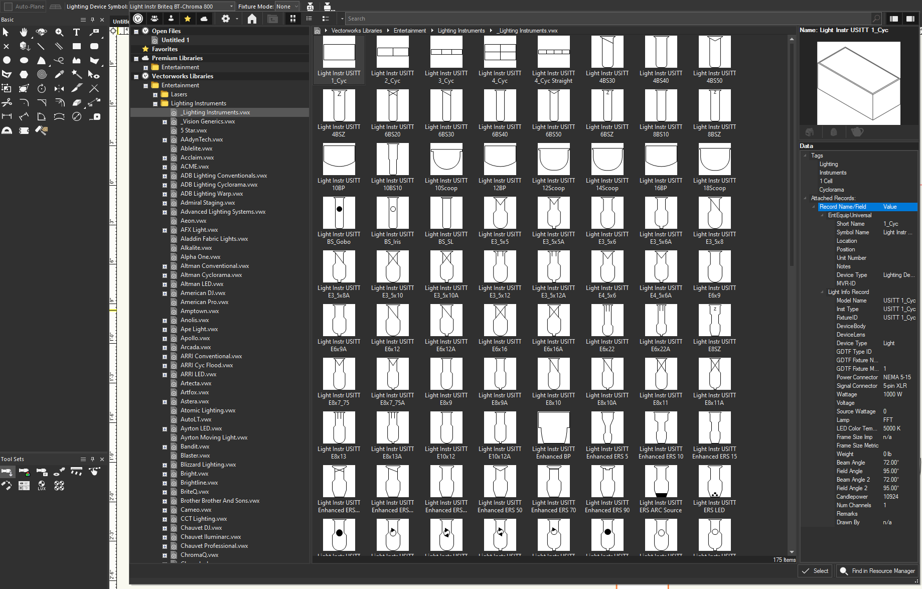
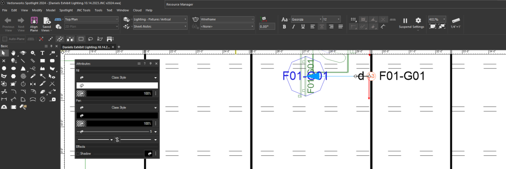
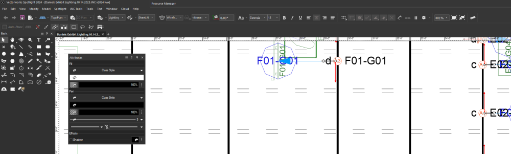
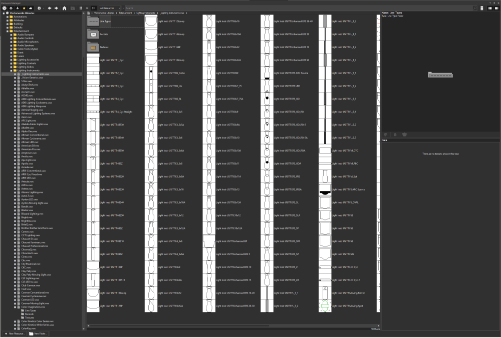
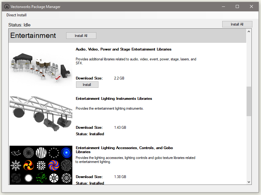
I think @Pat Stanford meant to link Jesse Cogdell @jcogdell instead of me, I don't work for Vectorworks. But, I can do my best to help you. Can you post a picture of either your Resource Manager or the Resource Pop-up from the Lighting Device Tool? Resource Manager: Resource Pop-up: You shouldn't necessarily need to download the full library, you can download files on demand as you need them, but could you also post a picture of your Vectorworks Package Manager? It can be found by going to Help - Download Content. Finally, which operating system are you running? I strongly recommend putting your system information and which version of Vectorworks you are using in your signature (it's not quite where you expect it, but Pat has a handy guide in his signature).

-
 I am on PC so I don't know if this is true for the Mac version, but while Import EPSF has been removed from the default workspace, it hasn't been completely removed from VW itself. If you open up the Workspace Editor, Import EPSF still appears under the Import/Export category. Again, no guarantee that this is the case on Mac, but it's worth a shot. But I definitely agree that VW should add an .svg import option, especially with icons within VW being changed from .png files to .svg files.
 -
Report of equipment contained in a given Layer
Jesse Cogswell replied to Cristiano Alves's topic in Entertainment
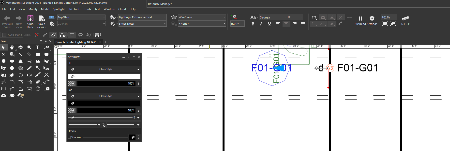
At the bottom of the Instrument Summary Object Info Palette is a button called Filters. This allows you to filter counts based on class, layer, position, or a custom string. I recently did a similar project where I proposed two different track layouts, one with horizontal track and one with vertical track. In this case, I could have used the Instrument Summary tool with a layer filter in place, as in this example: One thing to keep in mind with this approach is that these filters are applied to the object as a text string, so if you have a lot of filters turned on and you have long layer names, the text string becomes too long to parse and the summary will instead error out.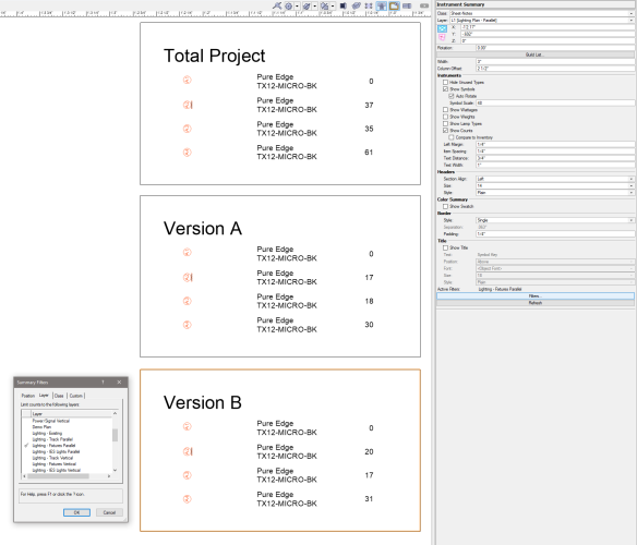
- 1 reply
-
- 1
-
-
I almost always have a statement like this in my PIO objects as part of the reset event or near the top of my driver before the event case: IF GetCustomObjectInfo(objName,objHd,recHd,wallHd) THEN SetObjectVariableBoolean(objHd,800,TRUE);
-
I wrote a script that can do just that back in early 2022. It builds a dialog box showing current class and layer visibilities for a given Viewport, selectable by a drop-down menu at the top of the dialog. It is somewhat smart, if you run the command with a Viewport selected or from within a Viewport Annotation container, it will initially set the drop down to that Viewport. I haven't used it in a while, so no guarantees how well it works in VW2023 or VW2024, but it should work in any version of VW from 2019 to current. Give it a look:
- 1 reply
-
- 1
-
-
create a viewport from the camera
Jesse Cogswell replied to Klaus Koch's question in Troubleshooting
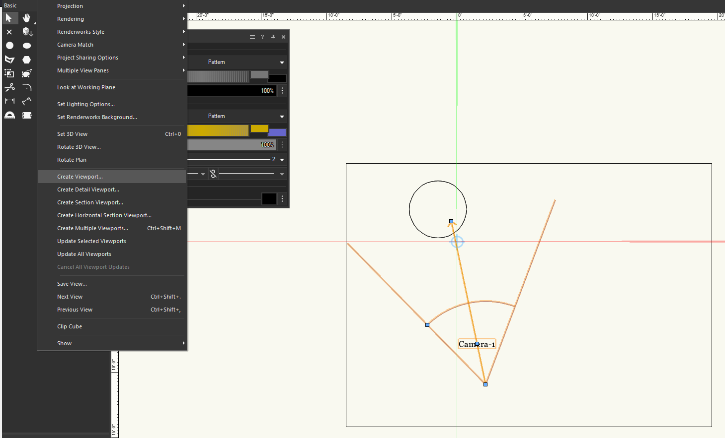
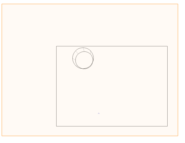
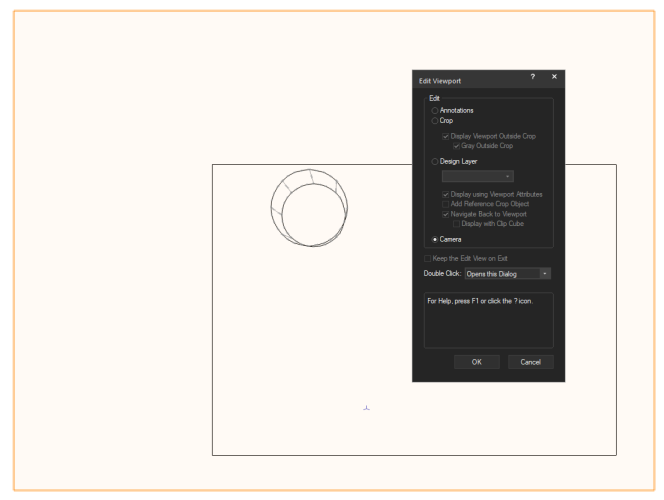
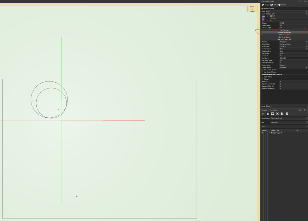
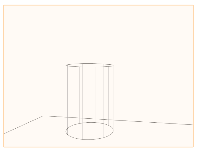
This is indeed an ongoing bug with VW2024. There is some good news if you're running Update 1, the kind of fixed it. When you first create a Viewport from a Camera, it will have the unfortunate top view. But if you double-click the Viewport and edit the Camera, you can click on the Activate Camera View button in the Object Info Palette to get your camera view back. You can then Return to Viewport and keep the desired camera view. You will need to do this each time you want to edit the Viewport camera. VW will always put you in a top view initially. There is additionally an ongoing bug with the Fine Tune Camera OIP button. When you press it after pressing Activate Camera View, it will bring up the camera adjustment like it's supposed to. The bug is that you can only adjust one slider at a time. If you touch a second slider, the changes made with the first slider will be reverted. So you have to adjust one slider, click OK to close the dialog, then click Fine Tune Camera again to adjust the second slider. Very, very tedious, but at least the camera tool kind of works now. Creating Viewport from Camera: Viewport Result: Edit Viewport Camera: Activate Camera Button: Proper Camera View: Final Viewport Output: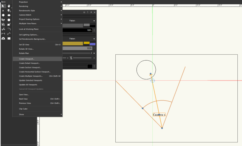
-
You can turn off the reminder dialog box by unchecking Confirm before save in the Autosave tab of Vectorworks Preferences. The only thing that complicates rendering is that you will get the little "Autosave Complete" message in the lower right of the screen that is normally used to show render progress, so you might not be able to see the render time or current render percentage.
-
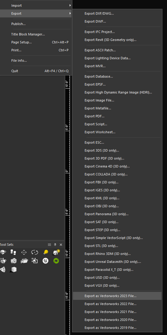
In the File - Export options, you should have an option to Export as Vectorworks 2023 File. But you are correct in that opening a VW2023 file in VW2024 will prompt you to save it as a new file with the v2024 suffix added (though not necessarily required). I wouldn't bother doing this with ALL of your existing files, I would do it only when I need to open and save a file from an older version. If you don't need to save your changes and are just opening a file to import resources or look around, there's no need to save the file in the new format. Keep in mind also that if a project uses referenced viewports or resources, all of the referenced files must be in the same format as the parent file. There is some caution, as constantly moving a file back and forth between 2023 and 2024 can lead to issues, especially with tools that see significant changes between versions (such as the window and door tools). Generally, it's best practice to keep everyone working on a project to the same version of VW to reduce the chance of such issues. Since I started using Vectorworks around 10 years ago, I have made it my regular practice to keep multiple versions of Vectorworks on my computer and to really only fully adopt a version once the next year's version releases (I've only started developing new drawings in VW2023 starting last September, I used VW2022 before that) unless a drawing really needs one of the new features. Unfortunately VW has a history of having some major bugs in their initial SP0 releases, and VW2024 is no exception. There are two major bugs preventing me from using VW2024 that have been targeted for fixes in SP2, set to release in November. I have been on the Service Select plan since 2015, so I have a serial number for each release between now and then and can freely install older versions, I don't know what the situation is for the new subscription model. If you have the option, my recommendation would be to reinstall VW2023 and continue using it until a project requires a VW2024 feature, then get the rest of the team onboard.
-
Why Doesn't VW Render the Beam Angles Correctly
Jesse Cogswell replied to User-B's topic in Entertainment
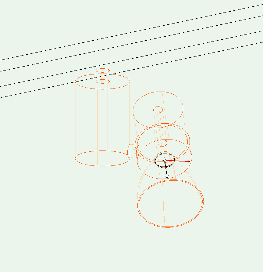
@Mark Aceto When did it last work? I just tested it in VW2019, VW2022, VW2023, and VW2024 and had the same result in each, the light reverted back to a standard Spot kind. I don't think I've ever gotten it to work, but would be very, very happy to be wrong. I currently use a combination of the two methods listed above. I'll use the gobo method while I'm developing my plot since it works well in Shaded rendering modes and once the plot is more or less locked in, I have a script that will place an IES Light at the center of the lens geometry for each selected Lighting Device object. The script then pulls the pan, tilt, intensity, and UUID from the Lighting Device. The UUID is applied to a record attached to the IES Light, so if the underlying Lighting Device moves, changes focus, or changes intensity then the script will update the IES light rather than building a new one. The only thing the script can't do is set the IES Light's Light Rotation Angle to match the lens rotation because there is no Vectorscript command to get to that field. It has sped up my rendering workflow by quite a lot. The nice thing about the script is that it also works for fixtures with light sources that are off-center, like the LSI Lumelex 2024 since the light will be generated from the lens geometry rather than the pivot point as it would from the Lighting Device Object: But IES Lights are far and away the best method of getting photorealism out of Vectorworks, especially if using a Redshift render mode.
-
Why Doesn't VW Render the Beam Angles Correctly
Jesse Cogswell replied to User-B's topic in Entertainment
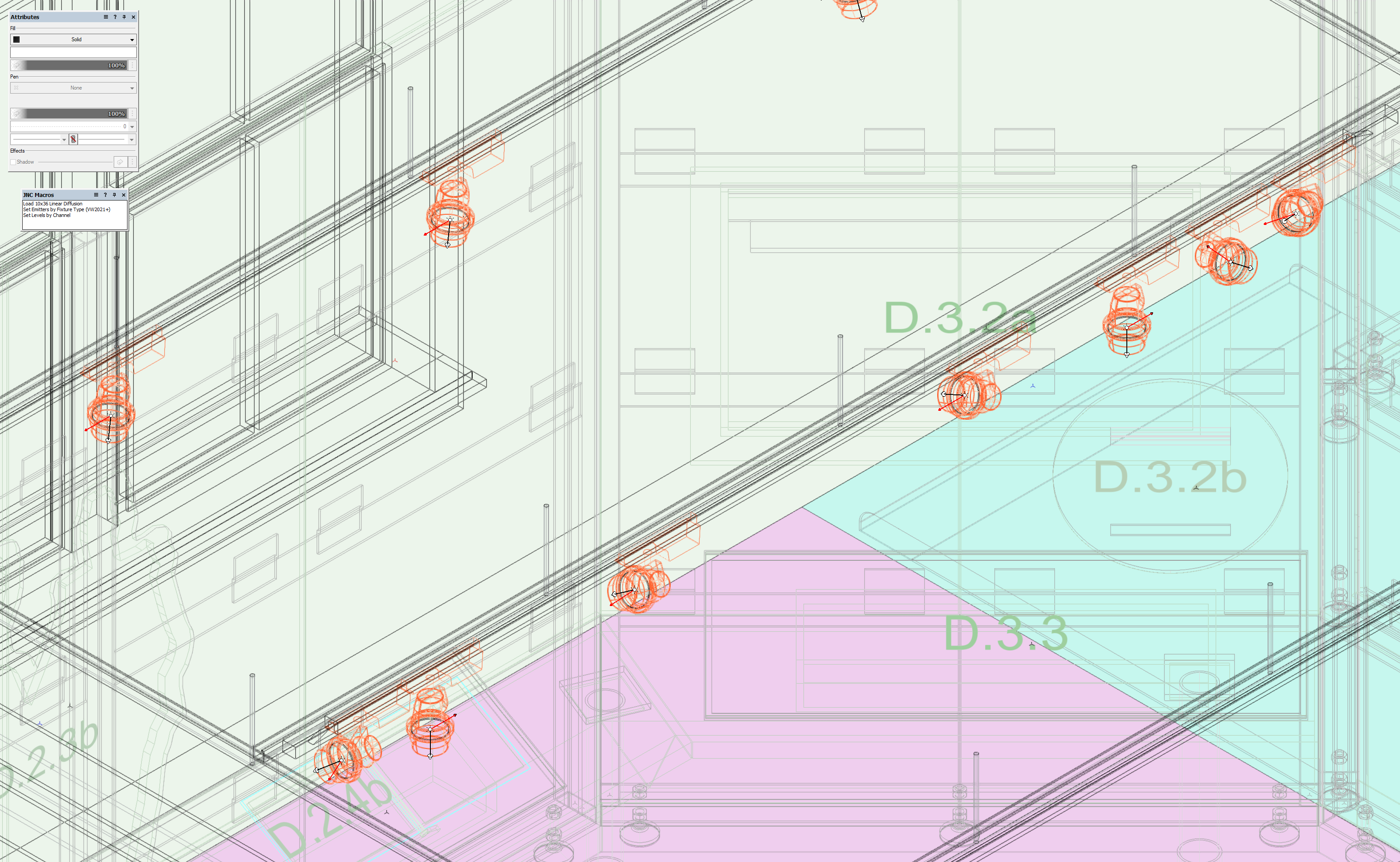
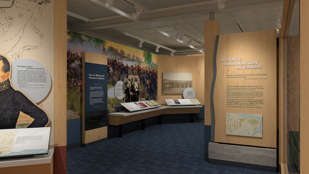
The ultimate answer is that the rendering engine in Vectorworks cannot render elliptical beams, only circular ones. This is a limitation of both Vectorworks and Vision. There are a couple of workarounds that I use to achieve this for rendering purposes. 1. Create a new Gobo Texture using Spotlight - Visualization - Create Gobo Texture that mimics the beam spread you want. I have an example posted here: It can be a little tricky to build, I built mine in Photoshop by taking a screenshot of an orthographic top view (much like you have in your example) with the beam and field filled using ovals. In Photoshop, I used the gradient tool in radial mode to feather the field angle and then layered in an additional oval for the beam. I've attached the Photoshop file used to build it. What this does mean, though, is that your Beam Angle 1 and Field Angle 1 fields in the OIP need to contain the wider size, and then have the Lamp Rotation Angle and Gobo Rotation set to 90deg to create a horizontal dispersion like in your example. Also, if you want to link this file with Lightwright, make sure that you apply the diffusion gobo in the Gobo 2 field and then make sure that you don't sync that field with Lightwright so you keep your Gobo Maintenance clean. To make applying this easy, I wrote a script that lives in the my template file that I run on any fixture that needs the elliptical beam spread applied. You just need to select the fixture, then run the script. I have it set to also turn on the Draw Beam, as I usually need to make adjustments to the lamp and gobo rotation for the shot I want. You would just need to change out the variable named kDiff to match your gobo texture. PROCEDURE LoadDiffusion; {* Sets parameters for selected Lighting Device object for rendering 10x36 Linear Diffusion lens in horizontal position Developed By: Jesse Cogswell Date: 1/9/2022 Revisions: *} VAR currentLayer:STRING; PROCEDURE LoadTheDiffusion(h:HANDLE); {Sets parameters of given Lighting Device object} CONST kDiff = '10x36 Linear Diffusion'; kLDevice = 'Lighting Device'; BEGIN SetRField(h,kLDevice,'Template',kDiff); SetRField(h,kLDevice,'TemplateRot1','90'); SetRField(h,kLDevice,'Lamp Rotation Angle','90'); SetRField(h,kLDevice,'Draw Beam','True'); LDevice_Reset(h); END; BEGIN currentLayer:=GetLName(ActLayer); ForEachObject(LoadTheDiffusion,((SEL) & (R IN ['Lighting Device']) & (L = currentLayer))); END; Run(LoadDiffusion); 2. The other workaround, which I now heavily rely on but may be cumbersome for you, is to use IES files with Custom light sources. If you don't know about them, IES files are text files that contain data to accurately recreate a light source's output. More information can be found here: https://ieslibrary.com/. These are very commonly used in architectural lighting, and most manufacturers will supply IES files for their lights. What makes these cumbersome is that you can't apply these files to Lighting Device objects, you can only use them with standard Light objects with the Type set to "Custom", so you would essentially have to add an additional custom light for each of your Lighting Device objects. If you are looking to produce photorealistic renderings, this is definitely the route that you want to take, but know that it's a lot of work to set up and maintain. Most of my lighting design work at this point is doing museum lighting, where photorealistic renderings are more important but where looks are also very static (no need to build cues with different intensities and colors). In my opinion, the IES method would be more work than it's worth for theatrical lighting. 10x36 Linear Diffusion.psd -
@Kevin Allen I am very much on your side and agree with you. Workspace editing could use more than a little work to make things both more streamlined and more customizable. That said, @ChollyO asked a question, and I answered it. I wish I had a better answer, but that's unfortunately the answer. Add a post (or upvote the many, many existing posts) in the Wishlist section.
-
The icons themselves are stored in a Vectorworks Resource File or .vwr. What you want to do is open up an Explorer window in your main Program Files\Vectorworks 2024 folder. In there, you should find a file called Vectorworks.vwr. Make a copy of this somewhere convenient, then change the .vwr file extension to .zip. This will allow you to extract the contents of the file using whichever software you prefer (I generally just right-click and select Extract All). This will give you access to a whole collection of things but what you're looking at in particular will be in the Images\ToolSets folder. Important things to note specific to VW2024 is that icons are no longer .png format but instead .svg format. You will no longer need to versions of the icon, one with the @2x suffix for high resolution displays, but you may need a second icon with a _dark suffix for dark mode. I imagine that if you wanted custom icons for your toolsets, you could extract the .vwr file, convert to .zip, and overwrite the icons in the file. Once you're done, you can re-zip the file, change the file extension back to .vwr, then replace it in the Program File. If you are going to go that route, I strongly recommend backing up a copy of the Vectorworks.vwr file somewhere in case something goes sideways.
-
Is there a way using Vectorscript to allow the user to select the face of a 3D solid (such as an extrude, sweep, Solid Addition, Solid Subtraction, or Generic Solid) and pull information about the face such as overall width / height and texture overrides? Bonus if you can get selective highlighting a la TrackObject.
-
Reshape Rectangles please
Jesse Cogswell replied to bcd's question in Wishlist - Feature and Content Requests
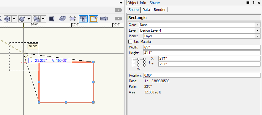
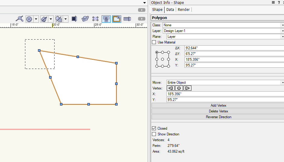
I played around with this a little bit, but I don't know what this would really gain. The rectangle already has reshape handles built in for general resizing, and any of the other reshape options (adding/removing vertices, hiding edges, etc) would make the rectangle not a rectangle anymore. What is interesting, is that if you use the Reshape tool and drag a marquee around part of the rectangle and resize from there, the rectangle will be automatically be converted into a polygon without a prompt. This goes back to at least VW2019. Initial Rectangle: Reshape tool w/ Marquee around corner: Result: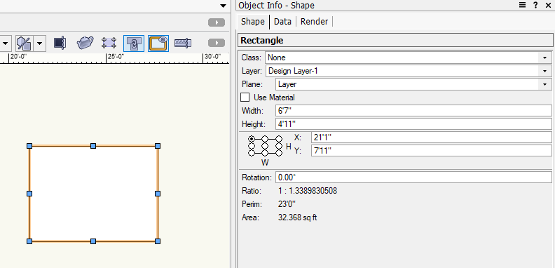
-
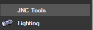
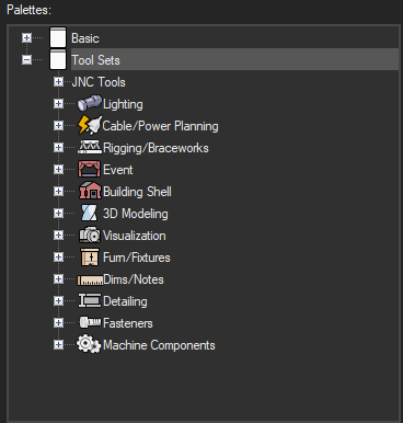
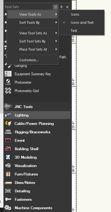
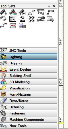
While it isn't quite what you asked for, you can at least add text in addition to the icons for both Tools and Tool Sets. You can edit this by clicking on the "hamburger menu" next to the Tools Sets title bar: This is something that I think the new GUI changes went a little too far on: removing color. In a push to make everything look "modern" and "mature", a good chunk of the interface shifted toward being monochromatic, but it makes it a lot harder to quickly distinguish things. Look how easy it was to see which Tool Set was active in VW2023:
-
I am not very well versed in Python, but I think the problem you are running into is that your d1 handle is not really pointing to your linear dimension. I made a simple demo in Vectorscript and AddVPAnnotationObject worked exactly as you would expect with a handle to the VP and a handle to the annotation object. For your code, try calling vs.LinearDim(vp1, vp2, 50, 0, 771, 770, 0.5) without the handle in line, but in the next line being d1 = vs.LNewObj(). After some noodling, I was able to hammer out a Python example as well, so it's not a problem with the Python implementation in VW. I've attached the example file to this post. It contains a script in both VS and in Python that will create a viewport of Design Layer-1 onto Sht-1 (currently hardcoded into both scripts because I'm lazy), set all class visibilities to Visible, then dimension the currently selected object and put the dimension in the new Viewport's annotation space. File is in VW2023 format since that's what you have in your signature. Python code is as follows: import vs kSheetName = 'Sht-1' kLayerName = 'Design Layer-1' kScale = 1003 objHd = vs.FSActLayer() sheetHd = vs.GetObject(kSheetName) layerHd = vs.GetObject(kLayerName) layerScale = vs.GetLScale(layerHd) vpHd = vs.CreateVP(sheetHd) BSB = vs.SetVPLayerVisibility(vpHd,layerHd,0) i = 1 while i <= vs.ClassNum(): BSB = vs.SetVPClassVisibility(vpHd,vs.ClassList(i),0) i += 1 vs.SetObjectVariableReal(vpHd,kScale,layerScale) vs.ResetObject(vpHd) A, B = vs.GetBBox(objHd) vs.LinearDim(A,B,50 ,0,771,770,0.5) h = vs.LNewObj() success = vs.AddVPAnnotationObject(vpHd,h) vs.AlrtDialog(str(success)) if success: vs.Layer(kSheetName) Annotation Example.vwx
-
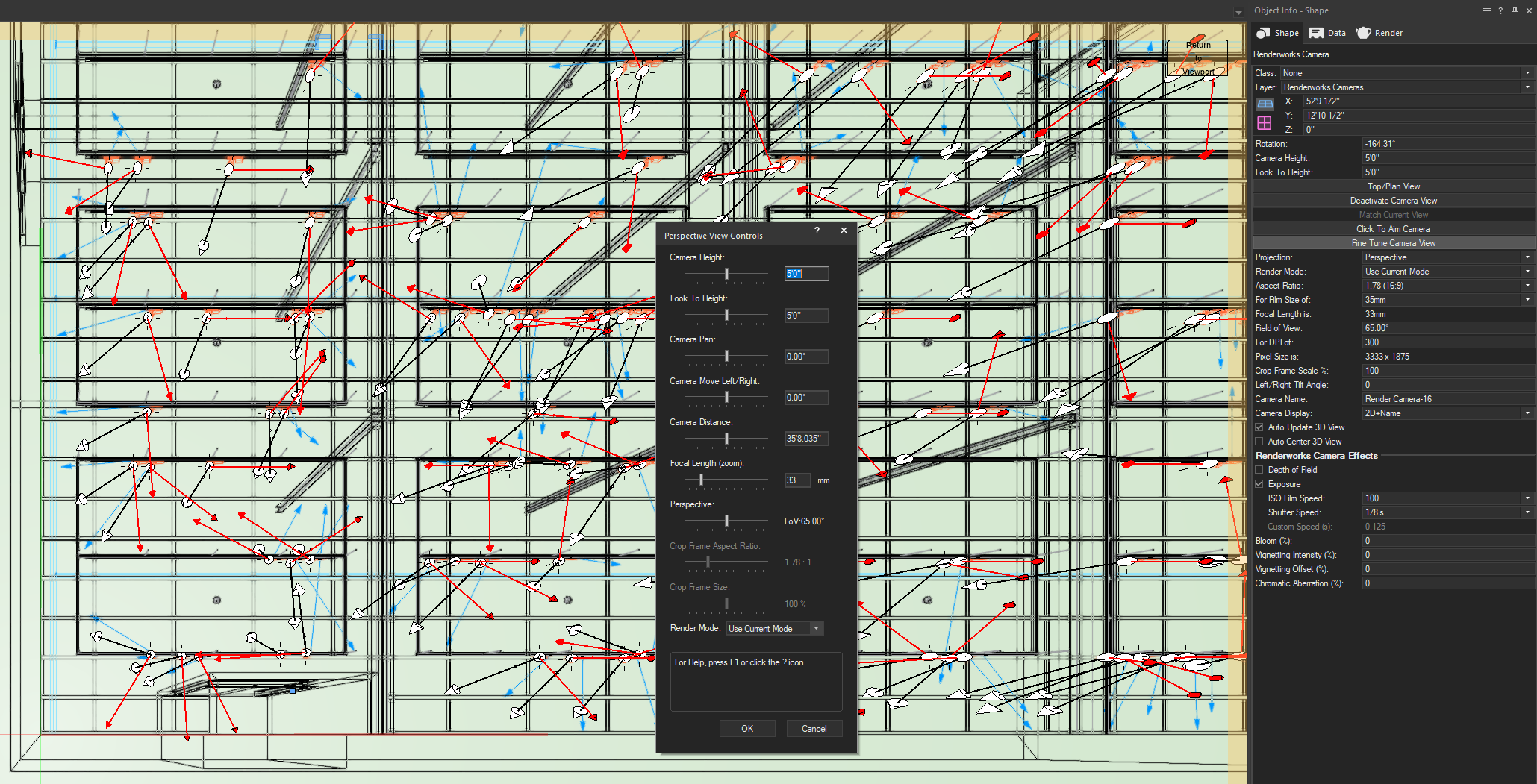
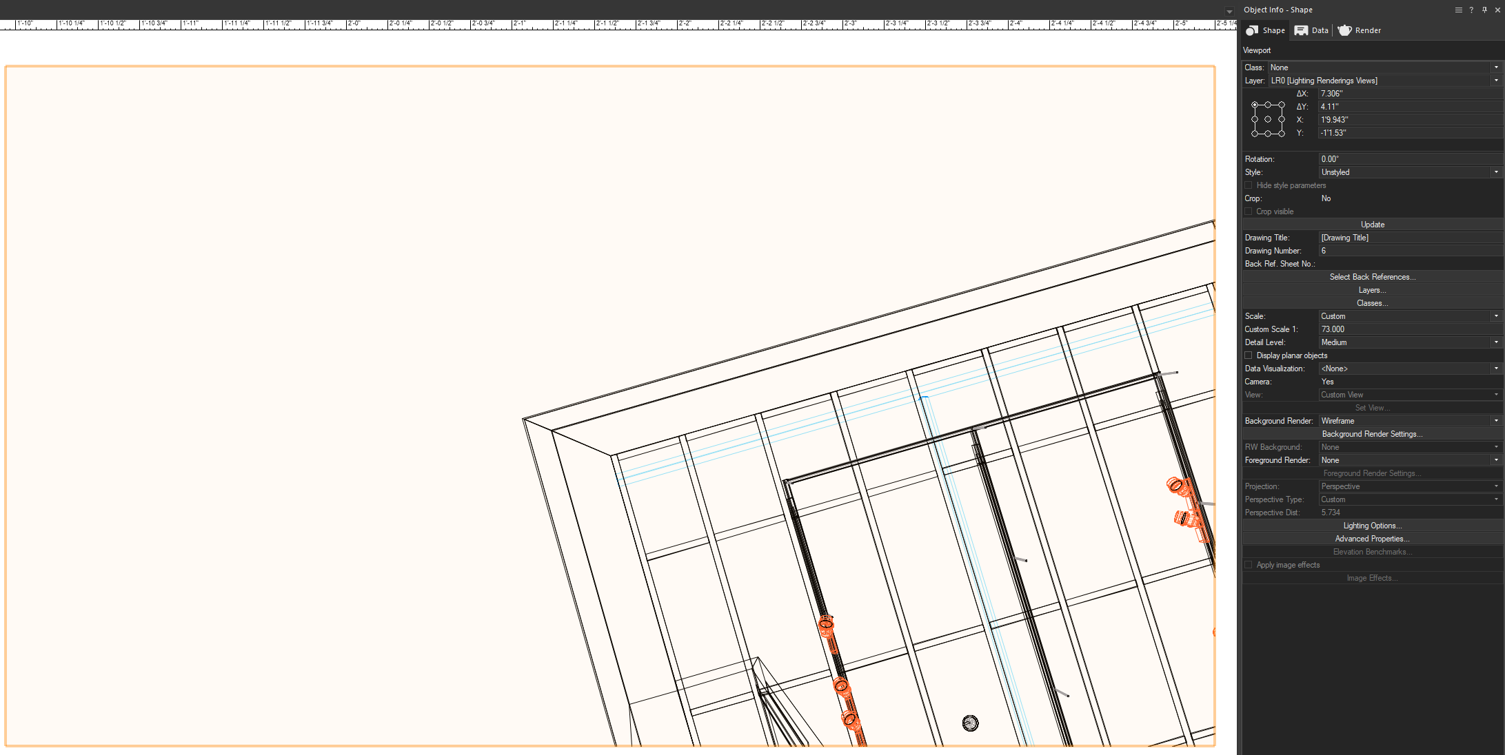
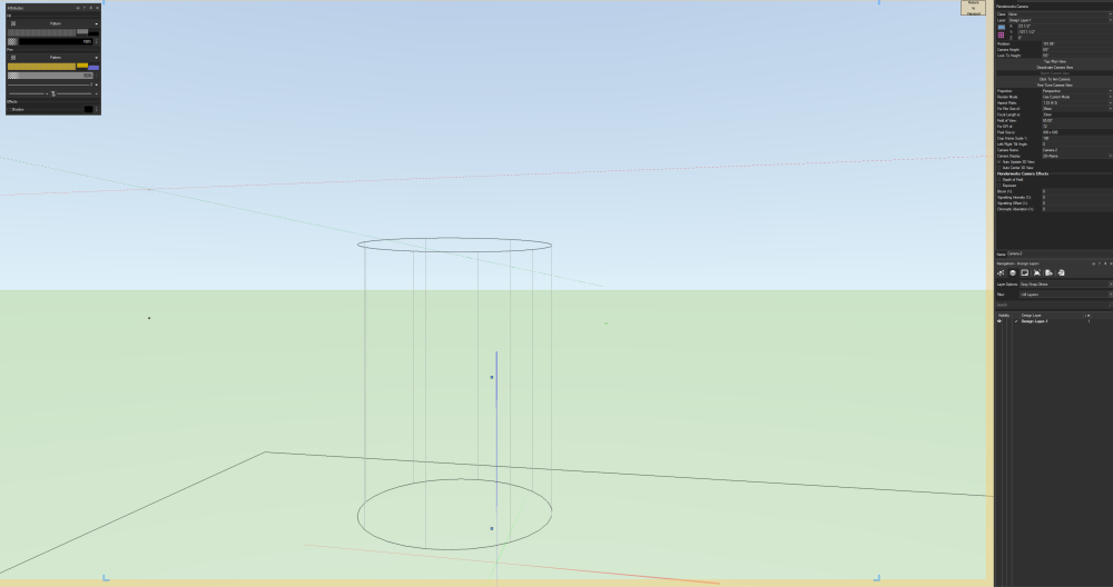
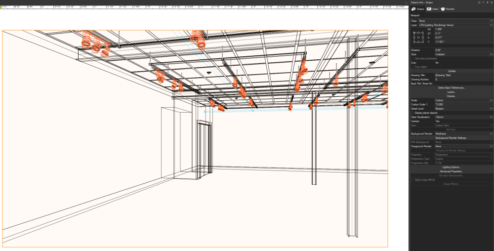
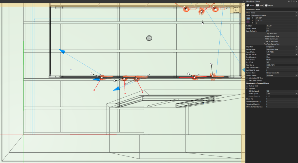
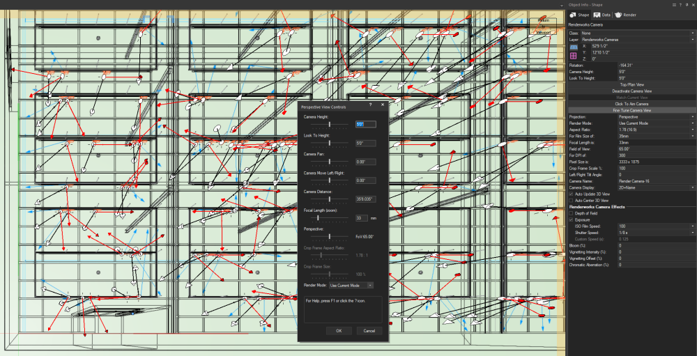
It seems that the Camera tool in VW2024 is entirely busted. I opened a drawing from VW2023 that had Camera-linked Viewports, and when I tried to edit the camera view by double-clicking and selecting Camera, the view instantly reverts to a top view as @Jeremiah Russell describes. If I exit the edit container, the camera is now locked to the top view, which is a problem. Viewport Before Editing Camera: View after entering Edit Camera mode: You can click on the Activate Camera button in the OIP to restore the view, but if I then click on Fine Tune Camera View, it reverts again to the top view, with only the Focal Length and Perspective sliders making any appreciable difference. On click OK from the fine tune, it reverts back to the top view that you had before the Focal Length and Perspective sliders. View shifted to Top after clicking Fine Tune Camera: What's also kind of nuts, is if you open up the camera edit, click Activate Camera to restore the original view, then click Fine Tune Camera and click OK without making an adjustments (though I don't think moving the sliders actually changes anything), then Deactivate Camera, and finally click Activate Camera again, it goes to a weird "Dutch Angle" top view. With these issues, I simply CANNOT use VW2024 for most of my work. Renderings have become a pretty major component of my workflow, and the only way I can make the Camera work is by manipulating the Camera object itself through moving it around in plan and making adjustments to the OIP and not using the Fine Tune button. The problem is, once I've converted the Camera to a Viewport, I can no longer adjust the camera focus, so I have to nail down the camera view before creating the Viewport. This is, of course, a major bummer.

-
I looked back at one of my plug-ins that adds annotations to a viewport, you were right to use vs.AddAnnotationObject but I think you went wrong with the viewport handle. AddAnnotationObject isn't looking for a handle to the vp's annotation group, but for a handle to the viewport itself. The reason your AlrtDialog call is returning a NIL handle is because the annotation group doesn't exist yet since there are no annotations in the viewport.
-
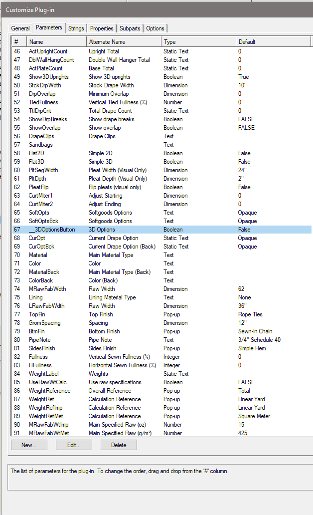
It looks to me like has lost its ability to be Event-Based. Events are what allow a plug-in object like the Soft Goods tool to have things like buttons and headers in the Object Info Palette. Every once in a while, a tool can break and temporarily lose this ability. Usually this can be fixed by restarting Vectorworks, but if this persists you might have to repair your installation to have the plug-in reinstalled. Could you do me a favor? Go to Tools - Plug-ins - Plug-in Manager. Click on the Built-in Plug-ins tab and find the Soft Goods tool. Click on the Customize button, then click on the Parameters tab. You should see the 3D Options button as parameter 67. Is this what you see? The other test would be to open up a new drawing and place a new Soft Goods object there. Does this new object have the button? If it does, there may be something weird with your drawing that is causing this feature to break.
-
VW2024 Dark Mode Custom Icons
Jesse Cogswell replied to Jesse Cogswell's topic in General Discussion
Thank you to @Josh Loy and @Stephan Moenninghoff, I was able to get my custom icon to work (rebuilt icon as SVG from original vector source) and now I can read my icons in Dark Mode. I'm not terribly wild about needing to have my Windows accent be that light, but it's important to me to know what I'm clicking. If it ends up annoying me down the road, I'll just switch back to Light Mode. After all, I've used it for the last 13 years and I'm pretty used to it at this point. -
VW2024 Dark Mode Custom Icons
Jesse Cogswell replied to Jesse Cogswell's topic in General Discussion
Extracting the Vectorworks Resource file and looking at the default icons, I appear to have been correct. Each icon has two versions, one standard and one with a "_dark" suffix. However, I can't seem to make any of my custom icons work even with the suffix. But when I use one of the default icons, it works as expected, so I must be doing something wrong. -
VW2024 Dark Mode Custom Icons
Jesse Cogswell replied to Jesse Cogswell's topic in General Discussion
It appears as though we have an option of either PNGs or SVGs now, the explorer window looks for both, though I'm guessing SVGs will be the now preferred file. The Help menu should be updated to notify us of the change. Super not looking forward to rebuilding a bunch of icons in the new format, though having it in a vector format will certain help in creating more legible small icons. My original point still stands, I can't get a custom icon in Dark Mode on Windows. I tested by building a super simple SVG file, just a single line with a non-uniform stroke in green. It works in Light Mode, but now doesn't even display a red X in Dark Mode, it just doesn't display an icon at all. It makes me believe that it wants two versions of the icon, one Light and one Dark. SVG Icon in Light Mode: SVG Icon in Dark Mode: Workspace Editor showing no icon loaded: