Jesse Cogswell
-
Posts
634 -
Joined
-
Last visited
Content Type
Profiles
Forums
Events
Articles
Marionette
Store
Everything posted by Jesse Cogswell
-
Which version of Vectorworks are you currently using? Also, when you double-click on the tool, you'll get a dialog box of the Object Info Palette settings for the tool, what displays in the Style field? Drawing Labels in VW have been made "styled" objects since 2021, so there should be a corresponding style in the Resource Manager. If you're just getting a locus point, it's likely that the tool is not looking at the proper Style resource to pull geometry from. What I would recommend doing is to open up the Resource Manager, navigate to the Vectorworks Library called Annotations - Drawing Label (styles) - Drawing Label.vwx. Find the style that you want to use (Drawing Label - Dwg. Sht No.), and import it into your drawing in the folder Drawing Label Styles, then make sure that is what the Style drop-down menu in the OIP shows. That being said, Vectorworks should automatically import the "default" style when you first run the tool in a drawing, so there's likely already a style in your Resource Manager. Personally, I'm not a very big fan of the change to it being styled and prefer the older tool. Good news for you is that the old tool is still in Vectorworks, and will work as before, but will not be able to be generated as part of Create Viewport (I prefer to generate my own anyway since I don't like where VW puts it). To get the old Drawing Label tool into your workspace, follow these instructions: Go to Tools - Workspaces - Edit Current Workspace to open the Workspace Editor Go to the Tools tab. In the box on the left, expand the category called Legacy In the box on the right, expand the Toolsets - Dims/Notes toolset Click and drag the Drawing Label (Old) plug-in from the box on the left to the desired toolset in the box on the right. Click OK
-

Select similar tool Issue
Jesse Cogswell replied to Vectorworks drafter Shiv's question in Troubleshooting
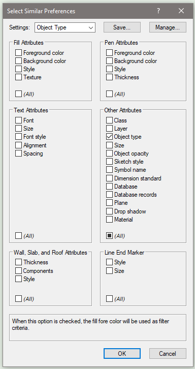
What @Jeff Prince is alluding to is that we cannot see what the current settings of the tool are, since you currently have it set to <Active Settings>. If you click on the wrench icon in the tool bar, it will open a dialog box showing your current settings. It also appears that you have Current Selection Mode engaged, so you would need to have objects selected before running the tool. If you select the first button as in my example above, Select Any Object Mode, the tool will work without needing to make a selection first. Now, on to the preferences. This tool must be configured to determine what "similar" attributes to look for. My guess is that you have something selected in your preferences that can't be applied to the objects you are trying to select, such as Database, Symbol Name, Text Attributes, or Wall, Slab, and Roof Attributes. What I'm guessing you are looking for is something like I have in my example, Object Type. You can also save "presets" of your settings to make quick work of bouncing between different settings. I have presets set up for Object Type, Class, and Symbol Name since those are the ones I most commonly need.
-
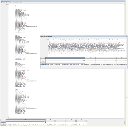
I have some good news! After doing some research, I have figured out how to handle Callouts, so the Reset Plug-in Obj Classes command posted above will now be able to force all Callouts to take attributes By Class. Updated command is attached here and has been tested in VW2019, VW2022, VW2023, and VW2024. For those playing along at home who want a little more background on how the Callout object works, the answer is surprisingly simple. The Callout object stores the visual attribute data for each of its components in a record field called __SubObjectDataAttributes as a JSON string. Using Python, you can parse the JSON into a Dictionary and then change the necessary key values before re-encoding back to a string and sending it back to the Callout object. The Python script is very simple and looks something like this (when acting on a selected Callout): import vs import json h = vs.FSActLayer() s = vs.GetRField(h,"Callout","__SubObjectDataAttributes") data = json.loads(s) for k in data["handles"]: k["penColorByClass"] = True k["thicknessByClass"] = True k["markerByClass"] = True k["opacityByClass"] = True s = json.dumps(data) vs.SetRField(h,"Callout","__SubObjectDataAttributes",s) vs.SetFillColorByClass(h) vs.SetFPatByClass(h) vs.SetLSByClass(h) vs.SetLWByClass(h) vs.SetMarkerByClass(h) vs.SetOpacityByClass(h) vs.SetPenColorByClass(h) vs.ResetObject(h) I should mention that the resulting JSON Dictionary in this case will have a single key, called "handles" whose value will be a List containing a nested Dictionary for each component of the Callout with the necessary information. I should also mention that the implementation that Vectorworks uses for the string data contains a lot of tab characters within the data between the keys and values. The script above will strip those tabs out, but as far as I can tell, doing so doesn't affect VW or the Callouts in any negative way and changing any attribute of an affected Callout will reset the formatting. Showing the __SubObjectDataAttributes in a Worksheet, left is a Callout before running the command, right is after running the command: I should also mention that you really have to use Python when handling the __SubObjectDataAttributes since the string length will be longer than the 2047 character cap that Vectorscript seems to have on strings. Reset Plug-in Obj Classes.vsm
-
I wrote a menu command to do something similar a couple of years ago. It essentially just does "Paste in Place" but on multiple layers at once. Just select whatever you want to appear on multiple layers, run Edit-Copy or use the relevant shortcut and run the command. It will detect whether the selected objects are on a design layer or sheet layer and will launch a dialog allowing you to select which layers to paste to.
- 1 reply
-
- 2
-

-
Creating and Filling a Resource Manager Symbol Folder.
Jesse Cogswell replied to Sam Jones's topic in Vectorscript
I think the reason your script isn't working is that you are using LNewObj to get a handle to your symbol folder. The handle to the newly created symbol folder won't be returned with LNewObj since the folder is not something created on a design layer. Instead, use TentSymFolder := GetObject(kRETentSymbolFolder) for the handle. Then it should work (at least it worked in a simplified version of your script where I didn't also import symbols from another drawing). -
SKETCH UP TO VW, Can't see the wall, materials
Jesse Cogswell replied to jichan's question in Troubleshooting
If I had to hazard a guess, I'd say that the SketchUp imported onto a different layer than the active layer, and that your Layer Options are set to Gray / Snap Others since that is the default. Either try to locate the design layer containing the SketchUp model, or go to View - Layer Options - Show / Snap Others. I almost always use Show/Snap Others rather than Show/Snap/Modify Others so that I can work on one thing at a time without accidentally selecting something in the background (selecting a piece of theater architecture while trying to select a lighting a fixture for example), but also know plenty of folks that have the opinion that, if an object is visible, you should be able to select it. Gray / Snap Others can be really great in helping to focus in on one layer at a time since it will gray out everything not on the active layer. -
draw an polygon spaced across a 2D path object
Jesse Cogswell replied to Jayme McColgan's topic in Python Scripting
@Jayme McColgan What you are looking for is using vs.GetCustomObjectPath to get a handle to the path object's underlying path, then using vs.PointAlongPoly or vs.PointAlongPolyN as @Pat Stanford suggested to get the X,Y point and vector (if you want to match rotation of the triangles to be tangent to the path). To space them evenly, I would use vs.CalcPolySegLen to determine the distance between the first and last point (use vs.GetVertNum to get the index of the final point), and divide that by the number of triangles you wish to insert. -
Changing a lighting symbol's hanging position
Jesse Cogswell replied to jloganthomas's topic in Entertainment
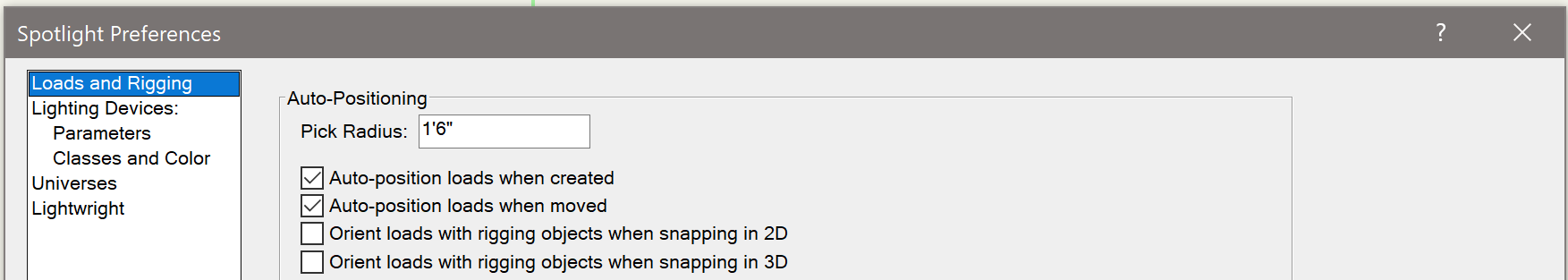
If you open up Document Settings - Spotlight Preferences and go to the Loads and Rigging tab, you'll see that there are two check boxes at the top: Auto-position loads when created and Auto-position loads when moved. You might have the first option checked but not the second option. The other thing to make sure is that there isn't anything between the lighting device and the hanging position, such as a locus or guideline (unless it's part of the position geometry). If you move a light onto something that is not a hanging position, even if a hanging position might be below that object, Vectorworks won't make the connection.
-
Worksheet stripe rows - alternate colours
Jesse Cogswell replied to Flair-Studio's question in Wishlist - Feature and Content Requests
@Flair-Studio I am upvoting this post because I would very much to see a revamp / upgrade to worksheets in Vectorworks, but I do have a couple of workaround plug-ins that might help you. The main plug-in in that post is for splitting worksheets so that they are easier to manage on the sheets. From your post above saying that you are managing a door schedule with 100 entries, the split plug-in might be helpful to you. What it essentially does is create smaller worksheets that reference the data in the source worksheet. For non-database worksheets, it creates a direct reference link, so as the master worksheet is updated, the split worksheets will follow. This doesn't quite work with database worksheets, so my plug-in instead copies the database data as absolute data in the split worksheets. This means that updating the master worksheet will have no affect on the split worksheets. However, if you run the command and select a master worksheet that already has splits, there is an option to overwrite the splits, which will the track across to any worksheets on a layer, so it's pretty convenient to update splits. There is another plug-in in that post that will "stripe" worksheets, letting you choose a color for odd rows and a color for even rows. This normally won't work on database rows, but if you use the Split tool, the resulting splits are not database rows, so the stripe tool will work on them. I wrote those plug-ins before I had gotten used to putting images (such as symbol images) into worksheets, so I don't think it will transfer the images over at the moment. If this is something you might need, I can look into adding that functionality. -
If you are using the Lighting Device object, which I suspect you are, the origin point of the beam is determined by a 3D Locus object located in the 3D component of the symbol. So if you scale the geometry of the symbol, you have to also move the 3D locus point upward. This locus point also determines the rotation point of body and yolk geometry based on pan and tilt.
-
2D shapes keep disappearing right after drawing
Jesse Cogswell replied to MGuilfoile's question in Troubleshooting
The one thing that is likely happening to you is that you have the Clip Cube engaged and your working plane is outside of the Clip Cube. If you go into a straight orthographic view and don't specify a new working plane or have Automatic Working Plane engaged, VW will place the working plane on X/Y 0, which is outside of the Clip Cube. -
Vectorworks does not compress texture images at all, so I'm guessing you're using a high resolution image as the basis for your texture. When you're setting up your texture images, you need to have an idea of what the texture is going to be used on. If it's going to be on a graphic label that's 1'x1' that's going to be in a small rendering at 300dpi, then it can be fairly low res. In general, I try to have my texture images be no more than 200kb each, making exceptions for textures on large objects or objects that will be taking up large amounts of page space in the final renderings.
-
I would think that you should be able to place your hoist with the code you have above, then use vs.SetRField(h,'BrxHoist','SymbolUsed',<SymbolName>) followed by a vs.ResetObject(h) to have the hoist reset with the desired symbol. The other option is to make a red symbol with the hoist with the settings "baked in" and then use vs.Symbol place it.
-
I am still struggling with what you want the plug-in to do. Do you want it to stay a path object, so as you manipulate it, the PIOs from the red symbols follow the path or is the path just for initially placing a group of red symbols? If you don't need the path after object creation, you can achieve what you are looking for using a Tool plug-in instead. If you do need to keep the path, you will use GetCustomObjectInfo to get a handle to your Plug-in Object, then feed that handle into GetCustomObjectPath to load the path into a handle. Then you'll use a FOR loop with GetVertNum and GetPolyPt3D to get to location of each vertex. Basic code for handling the path would look like this: PROCEDURE ExampleTest; VAR objHd,recHd,wallHd,pathHd:HANDLE; objName:STRING; numVerts,i:INTEGER; verts:DYNARRAY[] OF POINT3D; BEGIN IF GetCustomObjectInfo(objName,objHd,recHd,wallHd) THEN pathHd:=GetCustomObjectPath(objHd); numVerts:=GetVertNum(pathHd); ALLOCATE verts[1..numVerts]; FOR i:=1 TO numVerts DO GetPolyPt3D(pathHd,i,verts[i].x,verts[i].y,verts[i].z); END; Run(ExampleTest); This code stores all of the vertices of the path object into an array of 3D points. What you do with them from there is up to you.
-
Plant library not showing in VW resource manager
Jesse Cogswell replied to Jo Higgins's question in Troubleshooting
Make sure that you expand open the folders until you get to a .vwx file.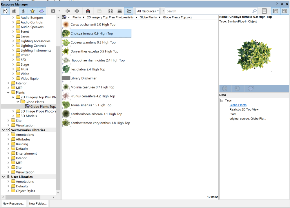
-
The biggest thing is that it doesn't work like the rectangle tool where you draw based on opposite corners, instead you click to once to start the rectangle, then click to set the width, then click to set the height, either by moving out from the center of the object or from the top/bottom depending on what's set in the mode bar. I personally find them clunky and dislike the extra click, so I only use them in instances where being able to use resize handles is handy or necessary. When I do, I usually write a Tool using GetRect to get the dimensions, then script out placing the Plug-in Object itself so that the user never has to use the awkward extra click method. But generally, most of my plug-ins that are rectangle shaped want to have very specific dimensions that are better to be typed in to the OIP rather than interactively sized, so point objects are the way to go. One other oddity is that the origin point for Rectangle PIOs is locked to one side of the X dimension (depending on which way the user goes after setting the first point), and center of the object on the Y dimension. With a Point PIO, you can basically make the origin anywhere you want. Based on what I've seen you building, my guess is that you would want the XY origin to be the center of the tube, which would not be possible with a Rectangle PIO.
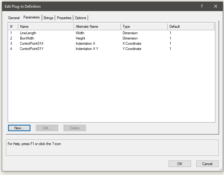
-
EDIT: Nevermind, it looks like you already got this far and I misread your question. @MullinRJ's advice in the next post is more likely to be what you are looking for. To get the parameters into the Object Info Palette, you need to build the plug-in object as a Point Object or Rectangle Object, right now it looks like you have it set to a Tool. If I were in your shoes, I would probably make it a Point Object to get around some of the oddities in placing Rectangle Objects. The post that I linked above and am linking again has all of the steps you need listed out. Look for the section called CREATING A NEW PLUG-IN, it has instructions on building the parameters. Essentially, you need to build the background record that serves as the plug-in parameters. You will set these parameters in a window that looks like this: The Name column will be the name that the script is looking for, referenced in script by that name with a capital "P" in front. For the example above, you would have code something to the tune of boxWidth:=PBoxWidth; The Alternative Name column will be what the parameter is named in the Object Info Palette.
-
@Mike Rock Taking a quick glance at your code and based on what you just posted above, the thing you are missing is a ResetObject function after your SetFillBack functions. You have RedrawSelection, but the object hasn't been properly reset, so the change doesn't update. The reason it works with SetClass, is that you are telling VW to change the class of the object (even though it's to the same class), which forces a reset.
-
The Look At Working Plane button is still there, but it's in one of the drop downs, the view one, maybe? Not sitting at my computer at the moment. It's just an added click like the Organization menu.
- 99 replies
-
- 1
-
-
- vectorworks 2024
- new ui
- (and 1 more)
-
This post that I wrote a couple of years ago might be useful. It's a basic crash course in creating Plug-in Objects in Vectorscript. This will cover setting up parameters and pulling their data as well as cover the basic structure and syntax of Vectorscript. Your code is not too terribly complicated, but I do have some questions/notes: I see you have a BeginXtrd function but not an EndXtrd function. Vectorscript will need the EndXtrd to finish the extrusion. Generally, my recommendation is to create the geometry first and then use functions like SetLW, SetFillBack, SetPenFore, SetFPat on the newly created geometry (passing LNewObj in as the handle) rather than change the settings and drawing the geometry later. This allows you to not have to reset the settings after your object is created. When using SetFillFore, SetFillBack, SetPenFore, and SetPenBack, you can get away with only setting the PenFore and the FillBack in most instances. When in doubt, make sure that the Fore and Back settings match (so that your SetFillFore and SetFillBack values are the same). Like with the settings, it's better to use SetClass on the created geometry rather than changing the user's class settings anytime they activate your tool. With the code you have, there is no need for you to have the line with objectHandle:=LNewObj, you can just use LNewObj unless you want to retain a handle to the original rectangle after creating another object (like if you were trying to combine two objects). I am confused why you are setting a drop shadow on an extrude, especially setting the drop shadow settings with SetDropShadowData and then disabling the drop shadow with EnableDropShadow(LNewObj,FALSE).
-
Unfortunately, I don't think that you will be able to fulfill your first request. From my understanding, due to the modal nature of VW, the reset and redraw won't actually register until your script completes. At least I've never been able to achieve what you are looking for. As for the second request, look into the Rpstr_SetValueInt and Rpstr_GetValueInt functions. They will do exactly what you are looking for, and will persist from one file to another. If you want it to reset when you run the command in a different file, you can use Rpstr_SetValueStr and Rpstr_GetValueStr to store the name of the currently open file. If the current filename (retrieved using GetFPathName) doesn't match what's stored in the string repository, you can use Rpstr_RemoveValue on the integer value to reset it back to its default (presumably 1), or just manually reset it in the dialog since the new value will be saved when you press OK anyway.
-
On Windows, when you press Alt once it highlights the top menu bar and allows you to go into a menu by pressing letter key corresponding with a menu item (F for File, E for Edit, M for Modify, etc). This will override workspace shortcuts. So, if you wanted the Mirror tool to have a shortcut of Alt + M, you'd be out of luck as it would just open the Modify menu. I had a colleague reach out to me this afternoon asking if this is a recent change, swearing that he used Alt+M as the Mirror tool shortcut. I'm reaching out to you all on the Forums with deeper institutional knowledge. From my understanding, this is behavior that has been baked into Windows since the beginning (the earliest I used was Windows 3.1, and I absolutely used the Alt + letter keys to jump through menus), but was Vectorworks able to override this on older versions? The oldest version I've used was 12.1, but I never tried to make a tool shortcut that would match a menu item. The earliest version that I have installed is 2019, and Windows will stomp on Alt shortcuts that match Menu Bar items. Does anyone know if this wasn't the case on earlier versions?
-
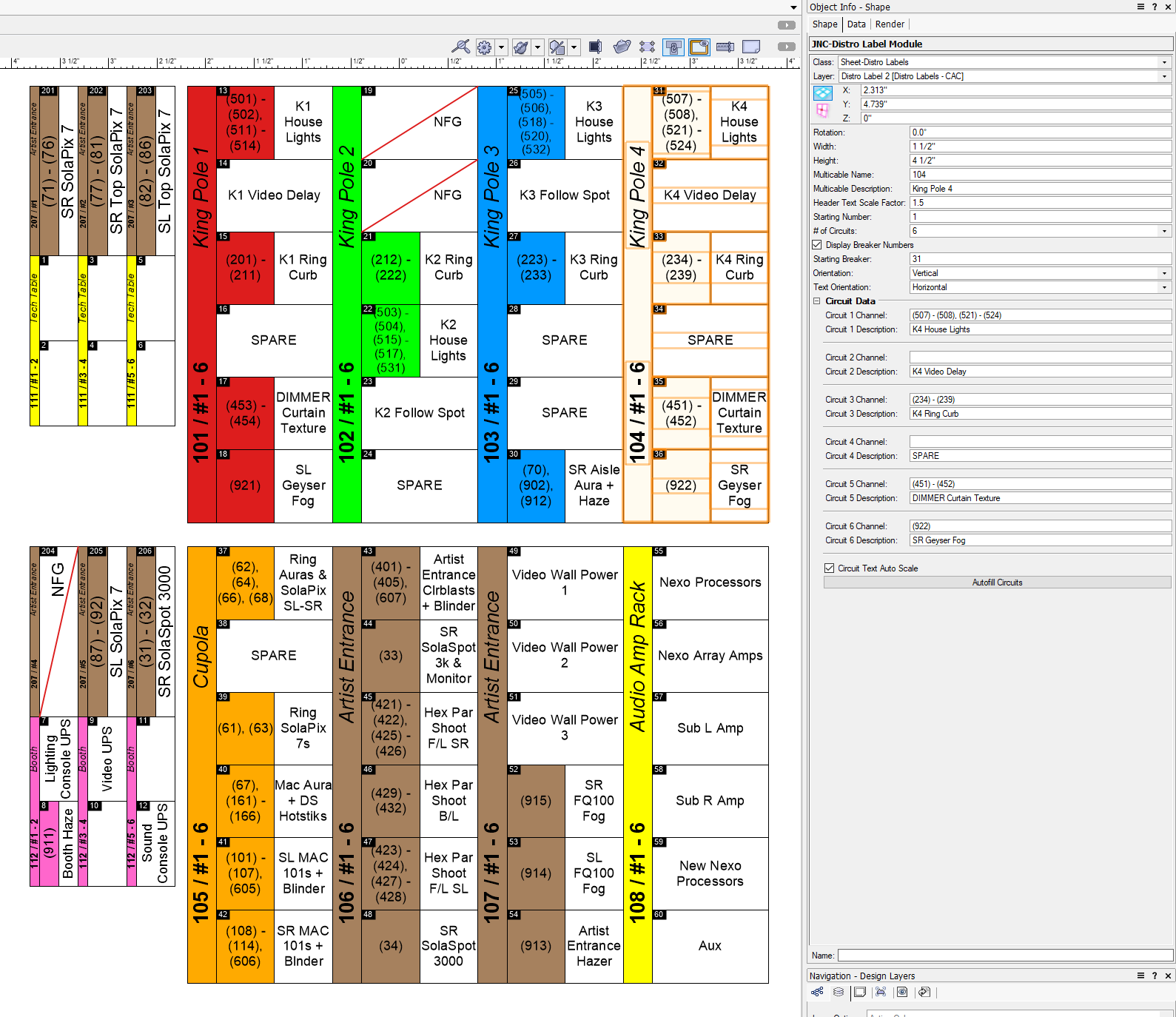
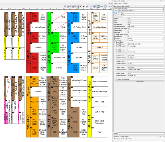
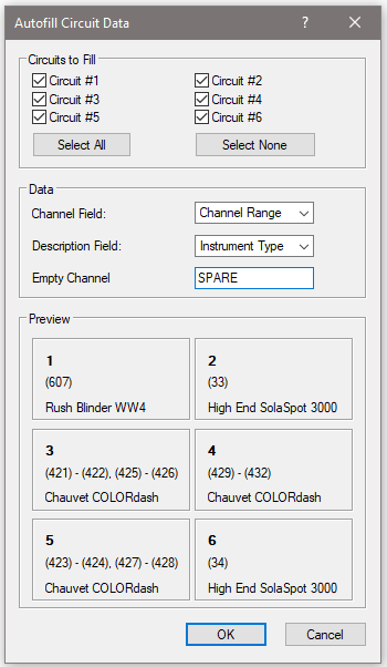
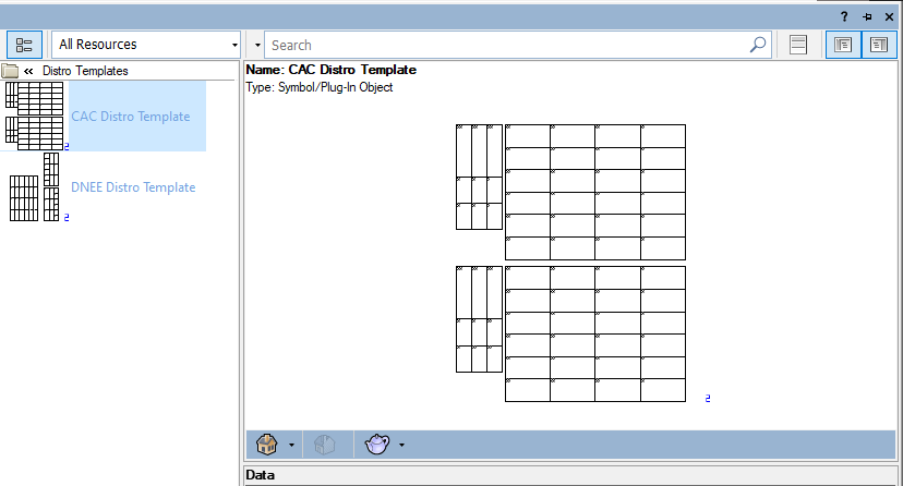
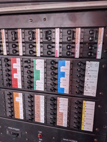
I wrote a plug-in for soca distro labels last year. It doesn't show phasing, but may work for your application regardless. It creates a "module" between one and six circuits for the purpose of labeling distro breakers. You can specify things like width and height, multicable name and description and starting breaker number. There are options for vertical and horizontal orientation for both the module itself as well as the text. The fill color of the object can be used to match color codes if your socas are color coded. I should note that this plug-in must be used with a layer scale of 1:1. It's best if used on a sheet layer. Even better, there's a button in the Object Info Palette that will auto-fill the circuit data based on the Circuit Name and Circuit Number fields of the Lighting Device object. VERY quick to generate. I also wrote a menu command called Create Distro Template for when you've set up a bunch of modules for a particular distro. Select the modules and run the command. It will ask for a name and then it will build a "blue" symbol consisting of the modules with the show data stripped out. Next time you use that particular distro, drop the symbol in, ungroup it, and you're ready to go to set up for your next show. I'll typically print these out on the Avery full sheet water-resistant mailing labels (like these), cut them out, and apply them directly to the distro. To install the plug-ins, follow the instructions below: Download the attached JNC-Distro Module.zip file, but do not extract it. Leave it as a .zip file. In Vectorworks, go to Tools - Plug-ins - Plug-in Manager Click on the Third-party plug-ins tab Click on the Install button Point VW to the downloaded .zip file Restart Vectorworks. A prompt should appear telling you to do it. Add the tools to your workspace by going to Tools - Workspaces - Edit Current Workspace Click on the Tools tab In the box on the left, find and expand the JNC category In the box on the right, open a toolset that you want the tool to appear in, such as Lighting or Event Design Click and drag the JNC-Distro Module tool from the box on the left to the desired toolset on the right Click on the Menus tab In the box on the left, find and expand the JNC category In the box on the right, find a menu to place the command in, such as Tools or Spotlight Click and drag the Create Distro Template command from the box on the left to the desired menu on the right Click OK to accept the changes and regenerate your workspace. Please let me know if you seen anything weird or if the tool doesn't work as expected. Based on asking about an A4 size sheet, I'm guessing that you are working in metric. The tool was written with imperial in mind but should work the same way in metric. I just haven't done thorough testing for it. JNC-Distro Module.zip
- 1 reply
-
- 5
-

-
-
Auto update texture when an image is changed
Jesse Cogswell replied to htranbos's question in Troubleshooting
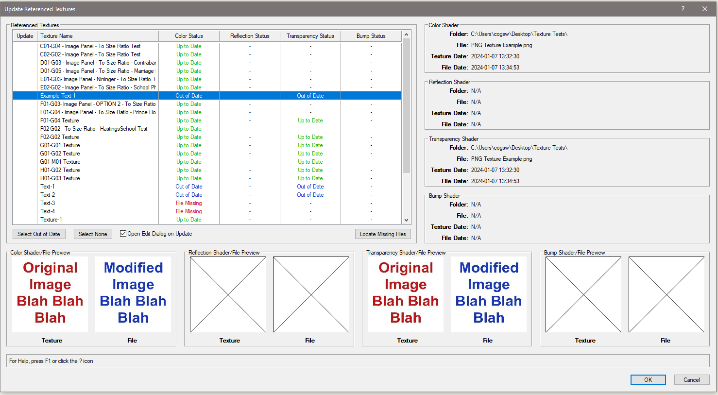
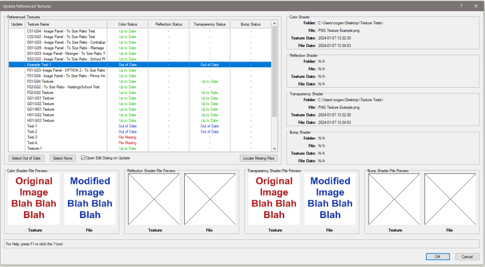
There is not currently a way to do this in Vectorworks. Even if you import your textures in as referenced Image objects and use those to create your textures, VW does not maintain the link between the Texture and the Image. This is, of course, less than ideal. I work with a bunch of exhibit designers who have mentioned that this is a major pain point for them during Design Development where graphics and text are constantly being revised so I wrote a couple of plug-ins to ease the process. Build Textures from Images Menu Command: At the top of the dialog box, there are options for naming incoming files. Generate a name from the filename with a prefix or suffix Start with a base name and iterate a number (IE Texture-1, Texture-2, Texture-3) You can select which Resource Manager folders the textures will be placed into. This dropdown should only display RW Texture folders. Pressing the Select Folder button will launch a file browser allowing you to select a folder to import from. A limitation of the Vectorscript means that the file explorer won't show what files are in the folders, just the folders themselves. Once you've selected a folder, all image files will be added to the List Browser in the middle of the dialog, with the Select and Color columns being selected by default. The List Browser is fully sortable and allows you to choose which shader the imported image will be used for (Color, Reflection, Transparency, and Bump). In the example above, I sorted by file type to select all .pngs and added the Transparency shader. This will remove white or transparent backgrounds for things like text. If a proposed Texture Name already exists as a named object in the drawing, the name will highlight in red. At the bottom of the List Browser has buttons to select all items, deselect all items, select only items with naming conflicts (more on this later), or deselect items with naming conflicts. At the bottom of the dialog box are settings for any List Browser items actively selected. If only one item is selected, the Texture Name text box will be active and populate with the selected item's name. As you edit the text box, it will actively change the value in the Texture Name column. Likewise, you can adjust the Texture Size or the target RM Folder fields (though these can be done for multiple selections). There is also a button for Get Name From Existing Resource, which will open a dialog box containing Renderworks Textures found in the drawing (in case you want to overwrite an existing Texture resource). Speaking of, in the lower right hand corner of the dialog box, there are a couple radio buttons that determine what will happen with any items with naming conflicts (red in the List Browser). By default, the option will be Overwrite/Merge. This will overwrite selected shader or add an image-type shader if one doesn't exists (like adding a Transparency or Bump shader to an existing Texture resource that just has a Color shader). Please note that there is a bug in Vectorworks where updating a Texture's shader image won't show on an object using that texture until either the drawing is closed and reopened, or the Texture's Edit dialog box is launched (you can even press Cancel or close the Edit dialog box and the object Texture will suddenly refresh). So I added a checkbox called Open Edit Dialog on Overwrite which will launch the Edit Texture dialog on any Texture being overwritten. You can either press Enter or Escape to close the Edit dialog, it won't really matter. If you are overwriting a bunch of files, it might be better to leave the checkbox unchecked and just save and reload the drawing. One other way to deal with naming conflicts is to Iterate Name. This will add a "-1" to the end of the proposed name and advance the number until it finds an open name. I was a little lazy with this one, so if you were to use this method on a texture named "Texture-1", it would start by trying the name "Texture-1-1" rather than "Texture-2". The final option is to ignore the Texture with the option Do Not Import. Any items with a naming conflict will be skipped In the lower left of the dialog box is a preview of the selected image. This will only populate if you have a single image selected. The only way I was able to get this to work was to add code to create a temporary Image resource from the image file, populate the preview, then delete the Image resource. If you have particularly large image files (in excess of 2 MB), it can take a while for this preview to populate and VW will hang a bit. But generally I would recommend having your texture images smaller than 1 MB in size anyway since your VW will get HUGE if you have a lot of large textures. When you press OK, the script will start the process of building each texture. This can take a little while as each texture will need to be individually updated, but you will see a progress bar and have the option to cancel if it's taking too long. For reference, building the 68 textures in the example above took 40 seconds. Much faster than building the resources individually. This command greatly speeds up texture import / creation but doesn't have much to do with your initial question. I made a small discovery that while you can't attach a record to a texture resource through the Resource Manager, you can absolutely attach a record with script. So, when you create textures using the plug-in above, it also attaches a record for each shader with the file name, path, and last modified date. Update Referenced Textures Menu Command: When you run the command, a dialog box will be generated listing all Texture resources with the attached record and a status for all shaders. "Up to Date" - The referenced file was found and the Last Modified date matches the record. "Out of Date" - The referenced file was found and the Last Modified date does not match the record. "File Missing" - The referenced file was not found in the file location stored in the record and will need to be located. Selecting any texture will populate the boxes on the right showing the record's folder location, filename, and last modified date for the shader as well as the current last modified date on the image file itself. For missing files, there is a button named Locate Missing Files, which will launch a file browser and allow you to select a new folder. If the file is found in that folder, the record will be updated and the status of the shader will be reassessed. You can select more than one texture at a time, so if you have moved all of your texture images, it's easy enough to get the record updated. One thing to keep in mind: the file path record will be updated as soon as the file is located with this method, even if you cancel out of the Update Referenced Textures dialog box. There are buttons at the bottom of the List Browser for Select Out of Date, which will put a check in the Update column for any texture with an out of date shader as well as a Select None to deselect any textures currently set to Update. There is a also an Open Edit Dialog on Update checkbox because of the bug mentioned above. If you're updating a lot of Textures and don't want to have to deal the the Edit dialog for each of them, leave this unchecked and save and reload the drawing. There are also image previews for each shader showing both the texture image and the current file image. Same warning about large image files applies here. Eventually, these plug-ins will be available for sale, but I still need to do some testing with them (particularly on Mac platforms). If you (or anyone else on the forums) would like to test them, I will send them along with installation instructions in a DM. Big shout-outs to @DomC for providing the undocumented but necessary object variable for locking in the image to the texture shader and to @JBenghiat and @MullinRJ for giving me the information needed to properly encrypt them with embedded Python code.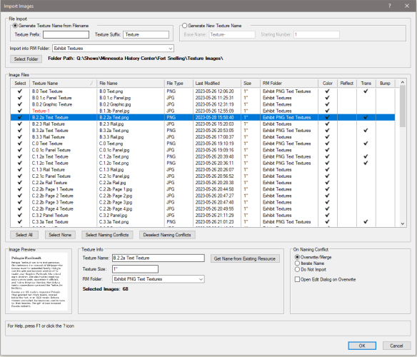
-
@Stefan B. Those actions are hard coded into the Truss object itself and won't appear in the Workspace Editor. The functionality would need to be recreated in a Menu Command by VW. It is worth a Feature Request as it shouldn't be too terribly complicated since the code already exists, but I wouldn't hold my breath for it.