Jesse Cogswell
-
Posts
634 -
Joined
-
Last visited
Content Type
Profiles
Forums
Events
Articles
Marionette
Store
Everything posted by Jesse Cogswell
-
 I also have a tool that can be used to track down any objects using a selected class, such as objects embedded in symbols, groups, viewport annotations, etc. It can be found in this post:
 -
Batch Rename enhancements
Jesse Cogswell replied to scottmoore's question in Wishlist - Feature and Content Requests
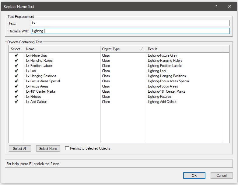
To anyone who uses the Replace Name Text tool that I posted above, I have a new version that fixes a few bugs and adds a couple of features. Fixed a bug resulting from unknown object types not found in the Function Reference Added a checkbox to limit name replacement for only selected objects (helpful when renaming Viewports) Allows for leaving the Replace With field empty, letting the user remove text Please let me know if anything breaks or doesn't work as intended. Installation will be the same as listed above. Replace Name Text.vsm -
@MarcelP102 is correct, this plug-in will work on any named object, including classes and layers. It makes renaming classes and removing parent classes really simple. To install, follow the instructions below: Download attached .vsm file Find your User Folder. The quick and dirty way to do this is to go to your Vectorworks Preferences, go to the User Folder tab, then click on Explore / Open in Finder. This will open your user folder in a separate window. In the explorer/finder window, find the Plug-ins folder and open it. Move the downloaded .vsm file into the Plug-ins folder. Restart Vectorworks. Now, you will want to add the menu command to your workspace. Go to Tools - Workspaces - Edit Current Workspace. Make sure that the Menus tab is selected. In the box on the left, expand the category JNC, you should see a command called Replace Name Text. In the box on the right, find a menu where you want to access the command (such as Tools). Drag and drop the command from the box on the left to the box on the right. Click OK. The tool allows you to have only look at selected objects (for renaming Viewports, for example), and the list browser is automatically sorted by object type. It looks at Plug-in Objects, Layers, Classes, anything with a name aside from Symbol Folders (there is a bug where changing the symbol folder name with a script doesn't properly update the Resource Manager, so the folder essentially disappears, so I removed that possibility). It will highlight whether the resulting change will cause a naming conflict with another resource as well. You can leave the Replace With text box empty if you want to remove text. Please let me know if you have any questions. I should also mention that this tool will work with any version of Vectorworks from 2019 to the current release (and presumably 2023, won't know until it releases). Replace Name Text.vsm
-
I wrote a script that can kind of do this back in 2021. It works great for none-database worksheets as it creates references back to the original worksheet. For databases, it unfortunately has to make the database data "absolute" in order to split up the worksheet, so it's best to do once the drawing is more or less finalized. Also, I should mention that, last time I tested it, it didn't properly pull images over, so if you're using it for a plant schedule with images of the symbols, it probably won't work for you. I unfortunately don't have the time at the moment to dig in and incorporate images right now, but it's theoretically possible.
-
CHANGE THE VIEWPORT VIEW (Cambiar la vista de un viewport)
Jesse Cogswell replied to MH2R's topic in Rendering
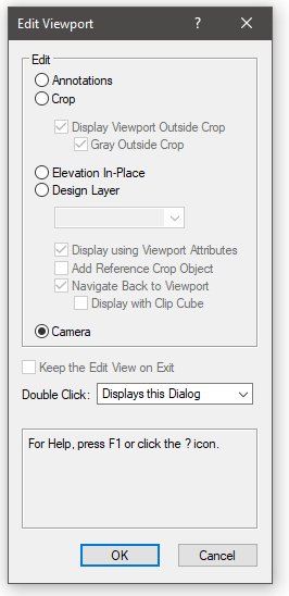
This topic is not related to Vision, which is a separate pre-visualization software owned by Vectorworks. To answer your question, what you need to start with is a RenderWorks Camera. In the standard workspace, you'll find it in the Visualization toolset, which has a lightbulb as an icon. Place your camera and get the view how you want it. Once that's done, select the camera, and go to View - Create Viewport. This will ask if you want to convert the camera or create a copy of the camera, choose whichever makes sense to you. After that, your Viewport will be created with the camera's view. Double-click the Viewport and select Camera as your edit target. Then you'll be able to make adjustments to the camera view. If you opt to make a copy of the original camera, the camera will remain independent of the Viewport (much to our chagrin). The only way to adjust the view is through the Camera option of the Edit Viewport dialog box.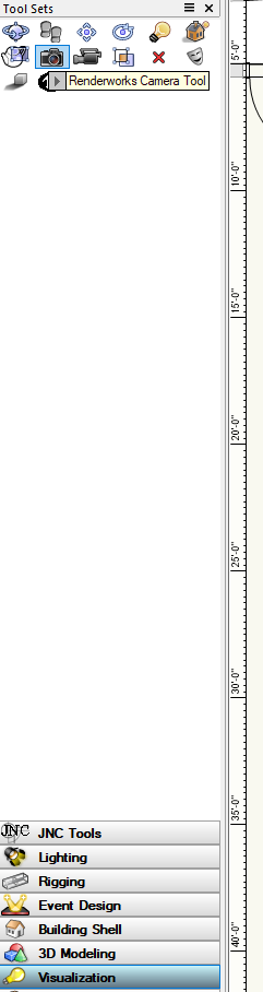
- 1 reply
-
- 1
-

-
Mostly possible. I wrote out a script that you can assign to a hot key to get into the crop and annotation space of a VP, but had a lot of trouble with the camera and could find no way for the Edit Section In-Place. To get these scripts to work on your machine, go to Tools - Plug-ins - Plug-in Manager. Make sure the Custom Plug-ins tab is active, and click on the New button. Select Command from the radio button list and click OK. Then click Edit Definition to give it a name and category. Then, click Edit Script and copy and paste the script into the editor. Do make sure that the Language drop-down at the top is set to VectorScript, since that's what these are written in. Then you should be able to find it in the Workspace Editor and assign a hotkey to it. Edit Annotations: PROCEDURE OpenVPAnno; {* Opens up selected Viewport Annotation Space Developed by: Jesse Cogswell VW Version: VW2022 Date: 9/1/2022 Revisions: *} CONST kEdit = 9743; kVP = 122; VAR currentLayer:STRING; PROCEDURE OpenAnno(h:HANDLE); {Opens annotation space of given viewport} VAR hAnno:HANDLE; BEGIN hAnno:=GetVPGroup(h,2); SetObjectVariableInt(hAnno,kEdit,0); END; BEGIN currentLayer:=GetLName(ActLayer); ForEachObject(OpenAnno,((SEL) & (L=currentLayer) & (T=kVP))); END; Run(OpenVPAnno); Edit Crop: PROCEDURE OpenVPCrop; {* Opens up selected Viewport Crop Space Developed by: Jesse Cogswell VW Version: VW2022 Date: 9/1/2022 Revisions: *} CONST kEdit = 9743; kVP = 122; VAR currentLayer:STRING; PROCEDURE OpenCrop(h:HANDLE); {Opens crop space of given viewport} VAR hAnno:HANDLE; BEGIN hCrop:=GetVPGroup(h,3); SetObjectVariableInt(hCrop,kEdit,0); END; BEGIN currentLayer:=GetLName(ActLayer); ForEachObject(OpenCrop,((SEL) & (L=currentLayer) & (T=kVP))); END; Run(OpenVPCrop); As for camera, I was not able to find a way to successfully "activate" the camera or open in the correct edit container, but I was able to get a handle to the camera object itself, so if anyone knows of an ObjectVariable or function that can get to the activated view of the camera from inside the viewport, please go ahead (and share with the class!). The code I have now identifies whether the selected VP contains a camera, and if it does, it goes through the list of named objects until it finds an object which has the Camera Attached to Viewport flag, then checks if it's the selected VP. If it is, it pulls the parent of the camera (which is the VP container) and opens it. This correctly opens the Viewport edit container, but not the same one that you would get by selecting Edit Camera in the VP edit dialog. There's a terrific chance that this is impossible with the current VectorScript function library (but I would be very happy to be wrong about this). What I have for code is listed below. I do have a commented out AlrtDialog that returns the name of the camera, just as a confirmation that the handle is correct. PROCEDURE OpenVPCamera; {* Opens up selected Viewport Camera if one exists Developed by: Jesse Cogswell VW Version: VW2022 Date: 9/1/2022 Revisions: *} CONST kEdit = 9743; kVP = 122; kVPCamera = 1037; kCameraAttached = 1038; VAR currentLayer:STRING; hCam:HANDLE; FUNCTION OpenCamera(hVP:HANDLE) : HANDLE; {Searches for cameras attached to VPs and returns handle to camera of given VP} LABEL 99; {Name Escape} VAR i,view:INTEGER; h,h2:HANDLE; BEGIN FOR i:=1 TO NameNum DO BEGIN h:=GetObject(NameList(i)); IF(GetObjectVariableBoolean(h,kCameraAttached)) THEN BEGIN IF(GetVPGroupParent(GetParent(h))=hVP) THEN BEGIN view:=GetObjectVariableInt(hVP,1007); h2:=GetParent(h); GOTO 99; END; END; END; 99: IF(h2<>NIL) THEN BEGIN SetObjectVariableInt(h2,kEdit,view); OpenCamera:=h; END; END; PROCEDURE CamCheck(h:HANDLE); {Checks if given VP has camera attached} BEGIN IF(GetObjectVariableBoolean(h,kVPCamera)) THEN hCam:=OpenCamera(h); END; BEGIN currentLayer:=GetLName(ActLayer); ForEachObject(CamCheck,((SEL) & (L=currentLayer) & (T=kVP))); {IF(hCam<>NIL) THEN AlrtDialog(GetName(hCam));} END; Run(OpenVPCamera);
-
Taking a quick glance, it looks like you are deleting the object h2 before you get to your if isSymbol check, so the prevObj = vs.PrevObj(h2) doesn't do anything since h2 would be nil.
-
One very important caveat not mentioned about Vision: you will need a console connected before you can do any meaningful rendering in Vision as there is no controls for lights within Vision itself. So if you go that route, you better have an Eos / MA / Hog / Onyx license handy that can output sACN or Artnet.
- 10 replies
-
- 3
-
-
- moving light
- rendering
- (and 2 more)
-
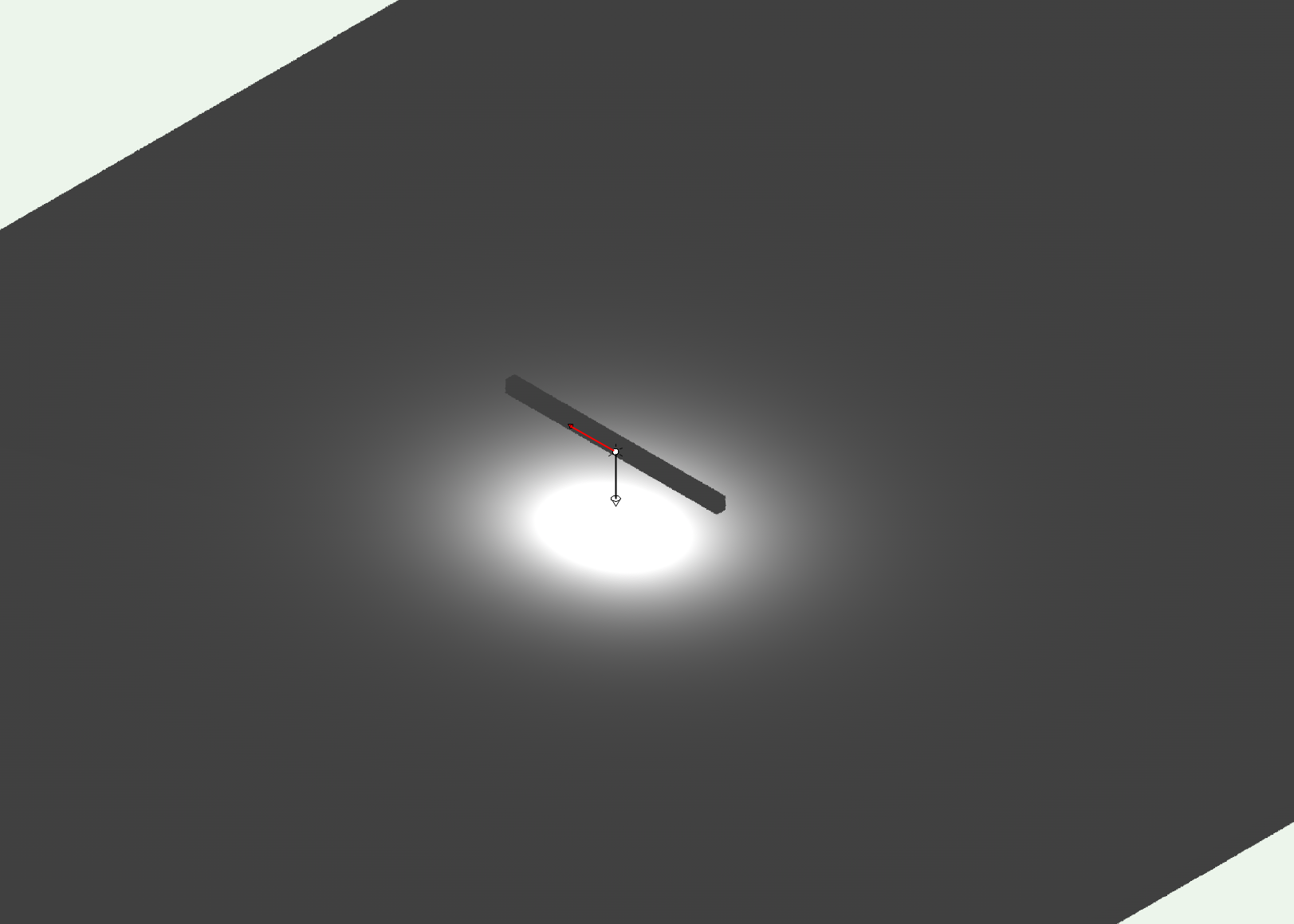
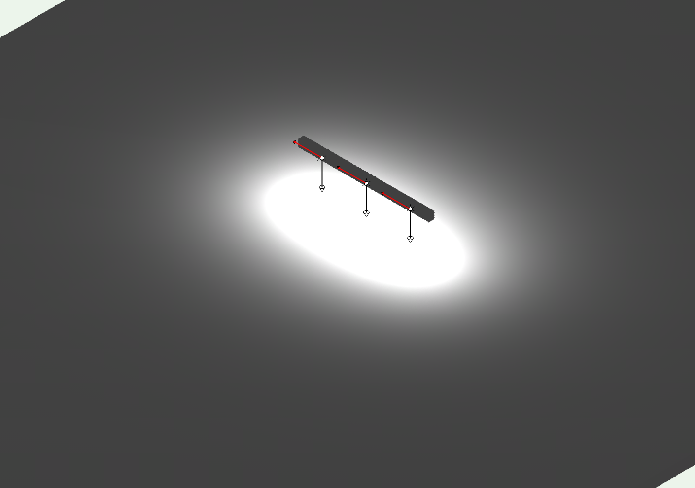
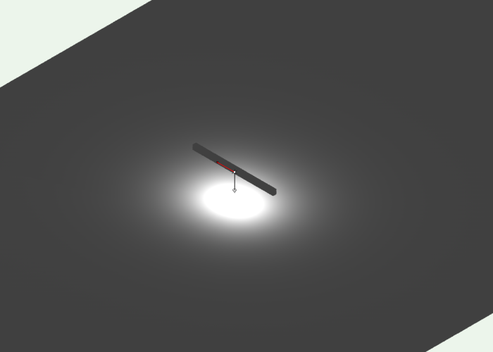
Good morning. I am trying to do some realistic rendering using some LED linear lighting fixtures and have a question regarding IES distribution files in Vectorworks. A standard IES file contains data for the luminous area dimensions (in my case, 3"x6'0"), but does Vectorworks actually use that data? Or do I need to distribute Custom Light Objects along the body of the fixture to get accurate output? If so, with what spacing? As an example, here is a screenshot from VW with the a symbol containing a custom Light at 2'-0" with a loaded IES file: You'll notice that the beamspread looks pretty circular, even though it wouldn't be in real life. Here is a screenshot from AGi32 (lighting calculation software) with the same fixture/IES file at the same height: This distribution looks much more like what I would suspect. I can mimic this somewhat by copying the custom light and spacing them out, but I would love to know the proper spacing to do this with so I don't mislead the client. Here's the custom light distributed every 2'0": Big thank you to anyone who knows the answer to this question.


- 1 reply
-
- 1
-
-
I have preferred to stick with Vectorscript myself, but also understand the larger application of Python being useful. I learned Python in 2010, a good number of years before it was integrated into Vectorworks, but didn't have much use for it at the time, so fell out of the habit. In the meantime, I became very familiar with Vectorscript and have been dragging my feet a bit in picking Python back up. In some ways, the Python integration is a bit "kludgy", being that you are still more or less locked into the Vectorscript functions when interacting with Vectorworks, but Python handles and organizes data much, much better. Sorting and searching arrays is MUCH easier in Python, and the Dictionary structure is pretty game-changing. If learning Vectorscript, you can't go wrong with the Vectorscript Language Guide that you linked above, it's how I was able to teach myself the language 12 years ago. If learning Python, there are a huge number of resources to look into, but it might take a bit of experimentation to apply that knowledge more specifically to Vectorworks. Either way, I cannot recommend enough keeping a copy of the Function Reference open anytime you're working on a script. In addition to the online one, an offline (and easier to navigate) one is stored in the VWHelp folder in the Vectorworks application directory. There, you will find a general description of each function and an example of the method constructor, and, if you're really lucky, a relevant example of how to use it. About a year ago, I also wrote up a quick "crash course" for Vectorscript for another user who was interested in getting started. It distills a lot of what you find in the Language Guide down to a slightly more straight forward how-to. Keep in mind that I wrote most of it in the wee hours of the morning, so it may get a bit loopy, but it may prove helpful. Do also be warned, this is how it begins. Once you start writing your own menu commands and plug-in objects, you might have a hard time getting yourself to stop...
-
Custom Circuit Boxes and Auto-Filling Labels
Jesse Cogswell replied to LSkulley's topic in Entertainment
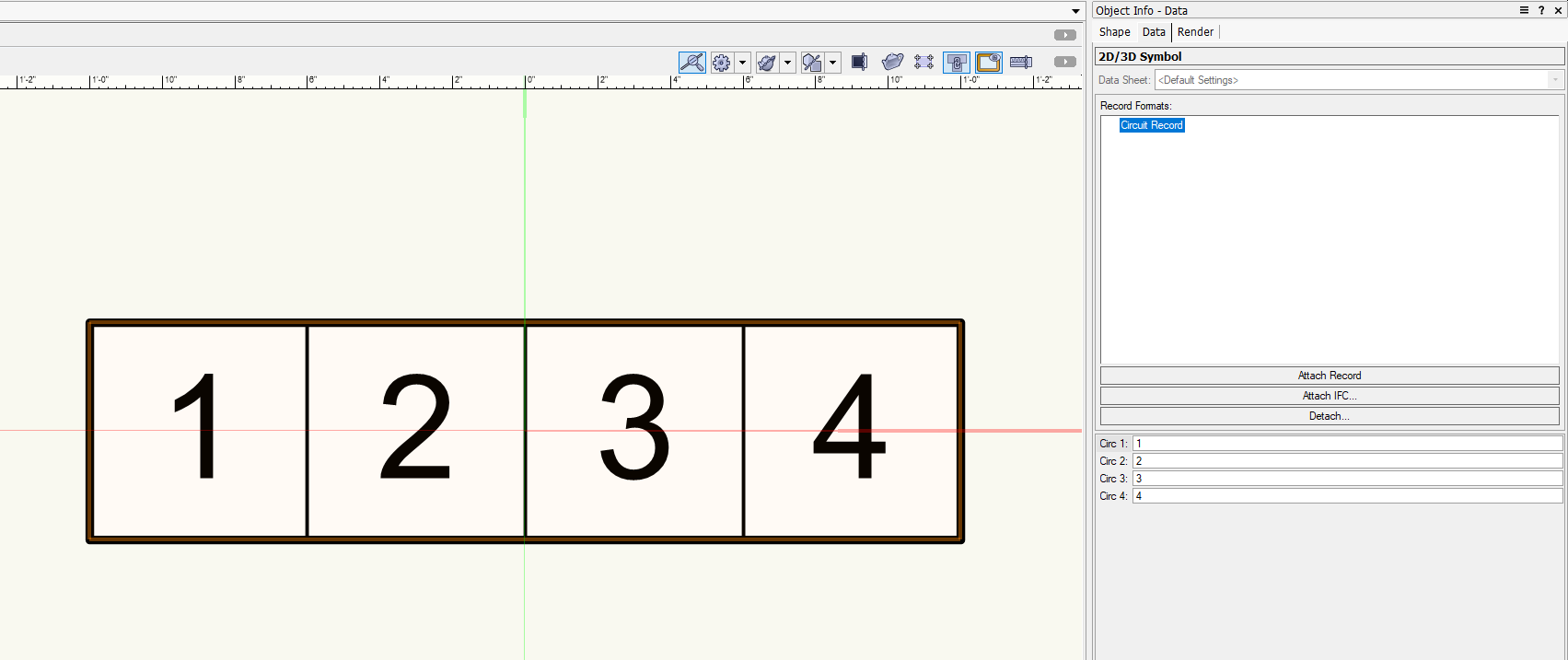
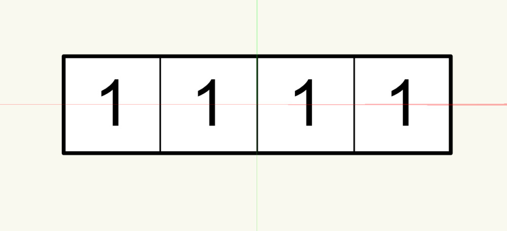
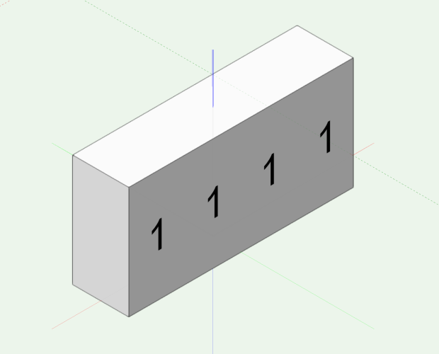
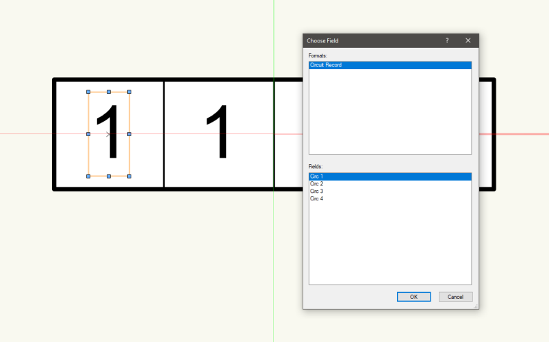
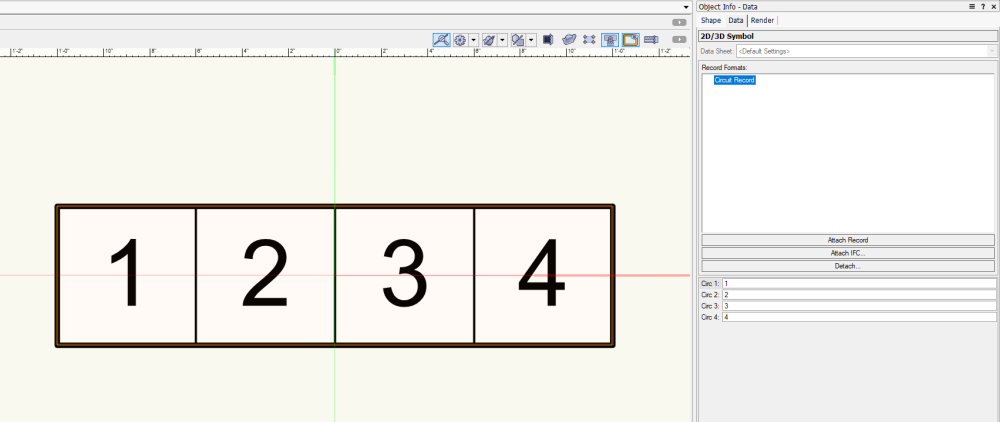
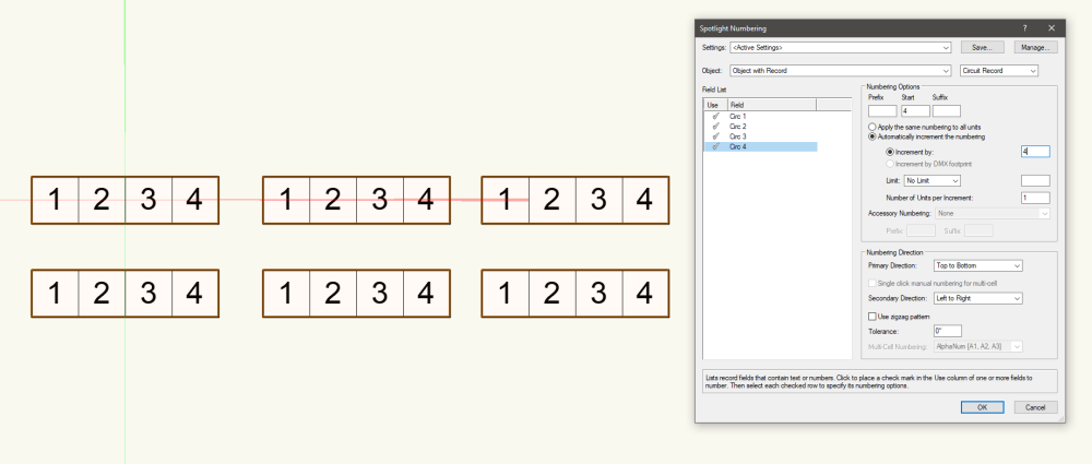
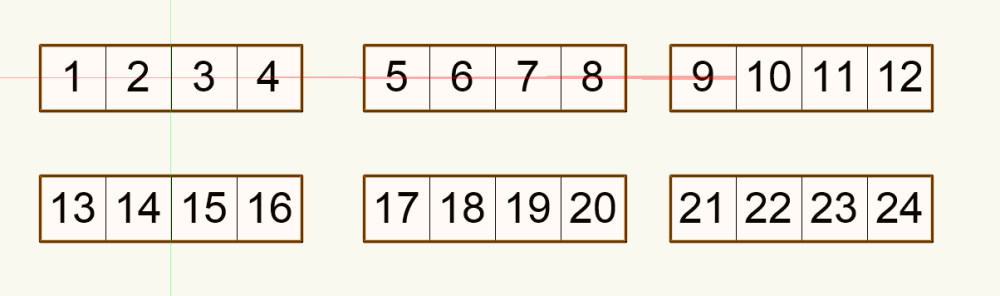
This is fairly simple and crazy powerful. I use record linked text in symbols all the time for labels, platform elevations, and title blocks. The process is as follows: First, build your record. For this example, I've included four circuits with their fields set to "text." I found that it's often times best to use "text" rather than "number" so that you can have circuits with a letter in them ("R" for relay, "W" for worklight, etc), and there's no huge advantage to having them as numbers, since you aren't going to be summing them in a worksheet anyway. It's entirely optional to have something in the default value, I will often leave it blank if it's going to be an object that doesn't always have a label, but in this case, I think it will be helpful. Four circuits are what I used in this example, but I would include the number of circuits for your largest box. Next, you are going to need to build your symbol. Include individual text blocks for each of the linked items. Don't really worry about what's in them for now, just make sure that it's not blank. This is a good opportunity to double check spacing. Also, make sure the text is formatted as you want it. Record linked text follows alignment, justification, and any kind of text wrapping that the source text box has. This also works with both 2D and 3D text, so if using a hybrid symbol and you want the text to appear in 3D, make sure to have text boxes with their plane set to 3D. Symbol 2D Symbol 3D Next, enter into the symbol edit and select one of the text boxes. Then go to Tools-Records-Link Text to Record. This will bring up a dialog allowing you to select the record and field to attach to the text. Do this for each text box. This can be really tedious if you have a lot of text boxes, so I recommend rebinding the menu command to something easy (I use Ctrl+R) using the Workspace Editor. Once you're done, you can change the circuits by using the Data tab of the Object Info Palette. Labeling things through the Data tab can be a little tedious as well. You can create database worksheets that can make things a little more convenient, or you can use Spotlight Numbering to do it for you. One major caveat of this is that you can't really have nested symbols with linked text, the linked text MUST be in the direct symbol. What this means is that you can't take two 4-circuit box symbols and use them to create an 8-circuit box symbol and still have access to the record fields. You can use Group, however, with the caveat that you will have to enter the group to edit the numbers unless you have a database worksheet. Record Linked Text Example.vwx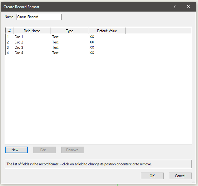
- 1 reply
-
- 1
-
-
@_c_ Had some success with this in Python. The same idea should carry over in Vectorscript since the Python implementation just adds a vs. prefix to the Vectorscript commands.
-
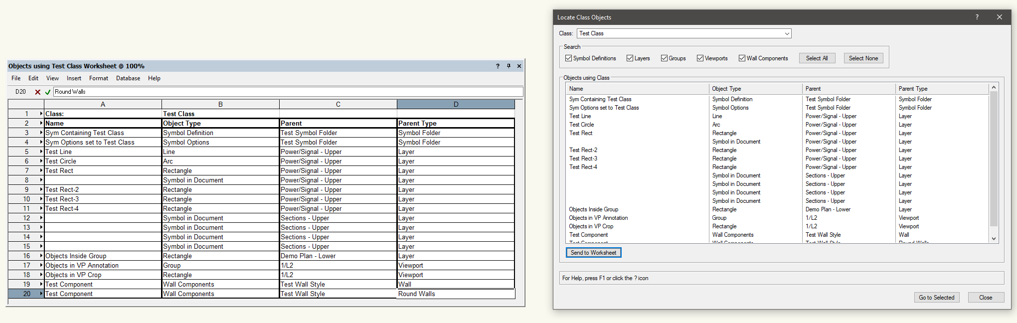
I wrote a tool that might help some of you out, though its use might be a little niche. The attached menu command will open a dialog which will list all items using the class selected in a drop-down. The tool will traverse symbol definitions, symbol options, groups, viewport annotations and crops, and wall components. Items directly on layers will be individually listed, items found within symbols, groups, and VPs will only list their parent. There is a box to dump the info into a Worksheet, or to go directly to a selected object. The behavior will be slightly different depending on where the objects were found: Inside Symbol Definition: The symbol edit window will be opened and all objects in the target class will be selected On Layer: User will be given the option to select only the selected row item, or to select all objects in the target class on the layer of the selected row item Inside Group: Opens the group edit window for the group and all objects in the target class will be selected Inside Viewport: Opens the Viewport Annotation or Crop edit window and all objects in the target class will be selected Wall Component: Selects wall centers view on wall There are options to filter what the tool searches through as well. The only thing this tool WON'T find is if an object in the target class is part of another object's path or profile group (such as the Extrude you guys referenced earlier). I'll try to think on ways to do this, but for now consider it a limitation of this tool. Please let me know if you need any help installing this or if you find any bugs. Locate Class Objects.vsm

-
@michnov There are two approaches to this. The first is to write a separate script for Increase, and a separate script for Decrease. Do this by going to Tools - Plug-ins - Plug-in Manager and creating a new Command. The scripts would look something like this, with the constant kAmount defining the scale amount. The scripts would look something like this: Increase: PROCEDURE IncreaseViewportScale; {Increase scale of selected Viewports by value of constant kAmount} CONST kViewport = 122; VAR currentLayer:STRING; PROCEDURE IncreaseScale(h:HANDLE); {Increases scale and resets given viewport} CONST kAmount = 5; kScale = 1003; VAR currentScale:REAL; BEGIN currentScale:=GetObjectVariableReal(h,kScale); SetObjectVariableReal(h,kScale,currentScale + kAmount); ResetObject(h); END; BEGIN currentLayer:=GetLName(ActLayer); ForEachObject(IncreaseScale,(SEL & (L=currentLayer) & (T=kViewport))); END; Run(IncreaseViewportScale); Decrease: PROCEDURE DecreaseViewportScale; {Decrease scale of selected Viewports by value of constant kAmount} CONST kViewport = 122; VAR currentLayer:STRING; PROCEDURE DecreaseScale(h:HANDLE); {Decreases scale and resets given viewport} CONST kAmount = 5; kScale = 1003; VAR currentScale:REAL; BEGIN currentScale:=GetObjectVariableReal(h,kScale); SetObjectVariableReal(h,kScale,currentScale - kAmount); ResetObject(h); END; BEGIN currentLayer:=GetLName(ActLayer); ForEachObject(DecreaseScale,(SEL & (L=currentLayer) & (T=kViewport))); END; Run(DecreaseViewportScale); You would then bind the scripts to shortcut keys through the Workspace Editor. These scripts would work for any selected viewports on the active layer. The other way to do this would be to make a user interactive "mode" that reacts to key presses. The following code could be put into a drawing by creating a new script through the Resource Manager or by making a new menu command through the Plug-in Manager. The way the code works is that, once started, it is listening for specific key presses, - to decrease the scale, + to increase the scale, and Esc to exit the mode. PROCEDURE ViewportScaleMode; {Allows user to scale selected viewports using + and - keys} CONST kMinusKey = 45; kPlusKey = 61; kEscKey = 27; kViewport = 122; VAR check:BOOLEAN; scaleAmount:REAL; keyHit:LONGINT; currentLayer:STRING; PROCEDURE IncreaseScale(h:HANDLE); CONST kScale = 1003; VAR currentScale:REAL; BEGIN currentScale:=GetObjectVariableReal(h,kScale); SetObjectVariableReal(h,kScale,currentScale+scaleAmount); ResetObject(h); END; PROCEDURE DecreaseScale(h:HANDLE); CONST kScale = 1003; VAR currentScale:REAL; BEGIN currentScale:=GetObjectVariableReal(h,kScale); SetObjectVariableReal(h,kScale,currentScale-scaleAmount); ResetObject(h); END; BEGIN currentLayer:=GetLName(ActLayer); check:=FALSE; scaleAmount:=RealDialog('Enter scale value:','5.00'); AlertInform('Viewport Scaling Mode','Use + and - keys to change scale, ESC to exit',FALSE); WHILE NOT check DO BEGIN IF KeyDown(keyHit) THEN CASE keyHit OF kMinusKey: BEGIN ForEachObject(DecreaseScale,(SEL & (L=currentLayer) & (T=kViewport))); ReDrawAll; END; kPlusKey: BEGIN ForEachObject(IncreaseScale,(SEL & (L=currentLayer) & (T=kViewport))); ReDrawAll; END; kEscKey: check:=TRUE; END; END; END; Run(ViewportScaleMode); One caveat of the second option is that you will get something of a "preview" of the viewport without annotations until the operation is complete. PLEASE NOTE: I wrote and tested the code on a PC. If you are running this on a Mac, there's no guarantee that KeyDown will return the same values, so there's a slight chance that you can get stuck in this mode if the Esc key number doesn't match up. Save all of your work before attempting to use this script. If needed, you can use the following script to determine the number of key presses in case you want to change the keys to something more to your liking or if the keyboards don't match: PROCEDURE KeyScript; VAR keyHit:LONGINT; BEGIN WHILE NOT KeyDown(keyHit) DO SysBeep; AlrtDialog(Concat('Key Pressed: ',Num2Str(0,keyHit))); END; Run(KeyScript);
- 1 reply
-
- 1
-
-
It looks like an edge selection highlight for applying something like a fillet or chamfer. I've noticed in VW in the past couple of years that every once in a while, a selection highlight will get "stuck" and not go away. Restarting VW is usually the way I fix it. If it goes away after a restart, you can likely ignore it. You might also try seeing if it appears in a Sheet Layer Viewport, just for the sake of curiosity.
-
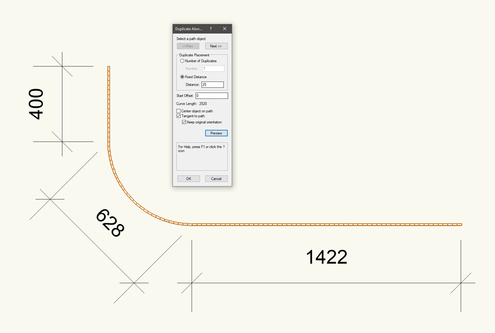
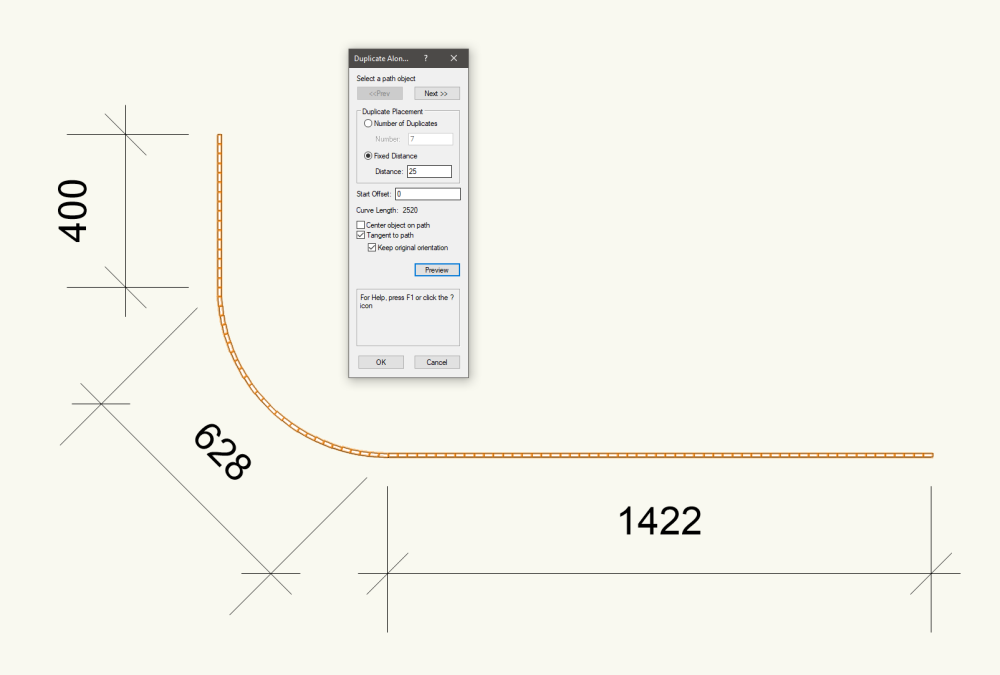
First, make sure that your path is all one object and not a 2 lines and an arc. Select all of the path components, then go to Modify - Compose. This will turn the path into a single polyline. Then you should be able to run the Array Along Path / Duplicate Along Path with these settings (Fixed Distance set to height of rectangle) and get it reasonably done along the path. You'll likely need to adjust the rectangles along the arc a little, but it's a good start. After the duplication is complete, you can select the patch and do Modify - Decompose if you need it back to being separate objects for the constrained dimensions.
-
Help with script to automaticly create wall hole object
Jesse Cogswell replied to MarcelP102's topic in Vectorscript
Got it. The example you posted above just had the ResetObject in the ResetThem procedure. -
Help with script to automaticly create wall hole object
Jesse Cogswell replied to MarcelP102's topic in Vectorscript
For the reset, you can save yourself a little bit of space by having the ForEachObject call use ResetObject directly, rather than a new procedure, as in ForEachObject(ResetObject, criteria);. Any procedure that is looking for a single handle can be used in this way, you would only need a separate procedure if you needed to do further work on them. -
Help with script to automaticly create wall hole object
Jesse Cogswell replied to MarcelP102's topic in Vectorscript
Try adding ResetObject(targetHd) before your SysBeep as well as a ReDrawAll. There is also a good chance that you need to do a reset on the parent wall, something to the tune of ResetObject(GetParent(targetHd)). -
Help with script to automaticly create wall hole object
Jesse Cogswell replied to MarcelP102's topic in Vectorscript
I was able to make it work using the following script: PROCEDURE Copy3DToWallHole; CONST kSymbol = 15; VAR targetHd,holeGroup:HANDLE; BSB:BOOLEAN; FUNCTION Extract3DFromSymbol(sym:STRING) : HANDLE; {Extracts Non-planar objects from given Symbol Definition and returns handle to 3D Solid} VAR h,tempHd:HANDLE; i,numSolids,result:INTEGER; solids:DYNARRAY[] OF HANDLE; BEGIN numSolids:=0; h:=FInGroup(GetObject(sym)); WHILE(h<>NIL) DO BEGIN IF (GetObjectVariableBoolean(h,1160) = FALSE) THEN BEGIN numSolids:=numSolids+1; ALLOCATE solids[1..numSolids]; solids[numSolids]:=h; h:=NextObj(h); END ELSE h:=NextObj(h); END; IF (numSolids > 0) THEN BEGIN tempHd:=HDuplicate(solids[1],0,0); FOR i:=2 TO numSolids DO BEGIN h:=HDuplicate(solids[i],0,0); result:=AddSolid(tempHd,h,tempHd); END; END; Extract3DFromSymbol:=tempHd; END; BEGIN targetHd:=FSObject(ActLayer); IF (GetTypeN(targetHd) = kSymbol) THEN BEGIN holeGroup:=Extract3DFromSymbol(GetSymName(targetHd)); BSB:=SetCustomObjectWallHoleGroup(targetHd,holeGroup); END; END; Run(Copy3DToWallHole); In general, I try to avoid using DoMenuTextByName whenever possible, reserving it only for things that don't have a Vectorscript equivalent or for launching one of my custom commands. The script uses FSObject to get a handle to the first selected object on the active layer. If that object is a symbol, it then uses GetSymName to get the name of the symbol definition. The Extract3DFromSymbol function uses FInGroup on the symbol definition itself and builds an array of handles to objects not on the screen plane using a WHILE loop. Even though VW2022 deprecates the screen plane, it is still used in the background to determine which objects are part of the 2D or 3D components of a symbol. If it's on the screen plane, it's part of the 2D component. A FOR loop then goes through that array and duplicates the objects using HDuplicate, then AddSolid to add them to the final solid. Once that process is complete, it uses SetCustomObjectWallHoleGroup on the originally selected symbol. There seems to be a bug in that the SetCustomObjectWallHoleGroup will not work when a symbol definition is passed in, but will if a symbol on the drawing is passed in, and the symbol definition will be updated accordingly. I tested this with fairly simple objects, if the 3D components are fairly complex, you might try adding in a CnvrtToGenericSolid command in to remove the nesting history from the Solid Addition. The SymbolToGroup command is a nifty trick but also something you have to keep an eye on. If it's run on a hybrid symbol, it will only act on the visible geometry at the time the command is run (will only convert the 2D geometry in Top/Plan view, or the 3D geometry when in a 3D view). Stepping through the individual objects of a symbol is usually the better bet since it will work regardless of which view you're in. -
Simple 3D File (no imports) major ram usage
Jesse Cogswell replied to Blind_Optimism's question in Troubleshooting
@zoomer Yup, I think they added that in 2021 or 2022. When you double-click an editable solid, you can select Edit Features, which will allow you to click on a face and go straight to the source object. It even builds the nesting structure into the Layer drop-down menu to let you jump to a specific point in the history. -
Simple 3D File (no imports) major ram usage
Jesse Cogswell replied to Blind_Optimism's question in Troubleshooting
Ooh boy, my laptop did not like that file. As I suspected, the objects you have made are very complicated nests of solid additions and subtractions. There is some good news as there is a very quick fix for you as long as you don't need to make any edits. If you select everything, then go to Modify - Convert - Convert to Generic Solids, it gets your file down to a MB in size and a whole lot more manageable RAM-wise (I've attached the file after this adjustment). I didn't want to remodel the entire thing, but I've also attached a document with just one of the panels modeled in the way that I would approach. You'll have a Solid Addition object for the panel, which will consist of a collection of Extrudes (double click the Solid to get into the editing where you can see the extrudes). The extrudes are constructed by drawing simple 2D shapes, then subtracting or adding surfaces together using Modify - Add Surface and Modify - Clip Surface. In this way, I traced your front panel using simple rectangles, with a rectangle for each hole, then subtracted. The rounded mounting feet is constructed with a rectangle and a circle, added together as a surface, then drawing another circle for the screw hole which is then clipped out of the other surface. Then it's extruded. One more thing to watch out for, Vectorworks gets really cranky when you have multiple polylines selected before running Model - Extrude. It will technically do it, with a single Extrude object consisting of seemingly disconnected objects, but you will see a bad hit in terms of performance. Same goes for sweeps, you want to only sweep one polyline at a time. I once inherited a drawing with a hundred lighting fixtures which were all built with sweeps, which were created a collection of lines and arcs that were all selected and swept at once. When I tried to create a Section Viewport, Vectorworks would crash. Once I went in and edited the sweep, grabbed all of the lines and arcs, and used the Modify - Compose command to create a single polyline, everything ran like butter. Electrical Box TS Convert To Solid.vwx Electrical Box TS Front Panel Remodel.vwx -
Simple 3D File (no imports) major ram usage
Jesse Cogswell replied to Blind_Optimism's question in Troubleshooting
@Blind_Optimism You do have to be a bit careful with using the Push/Pull tool in Vectorworks. If you are using it in the first mode (Extrude Face Mode), every time you change a surface, you are creating a new solid subtraction or solid addition. Vectorworks saves the history of all of this to allow for you to make changes later, but you can end up an object that is a solid subtraction inside a solid addition with tapered extrudes inside another solid addition. All of this nesting does increase file sizes and I can only imagine affects memory use as well. When using Push/Pull, it's probably better to use the Move Face Mode, which will move the faces but turn the object into a Generic Solid, which limits the changes you can make to it, but is much easier on memory usage. Personally, when 3D modelling I do all of the addition and subtraction operations manually to try to keep things in the fewest instances of "nesting" as I can get away with. If I need a box with a hole in it, I think of a way to have that hole be part of the polyline that gets extruded in order to cut down the number of boolean operations to create the final shape. I also try to "bundle" operations together. If I need to have multiple holes punched into a 3D shape, I create a cylinder for each hole, then select all of them and the original shape and run Model - Subtract Solid to punch the holes all at once, rather than doing it for each hole. That way, it's also a lot easier to edit later as I don't have to keep going into layers of the "nest" to finally get to the right subtraction operation when I need to move something. -
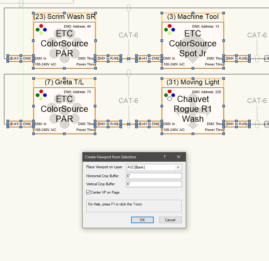
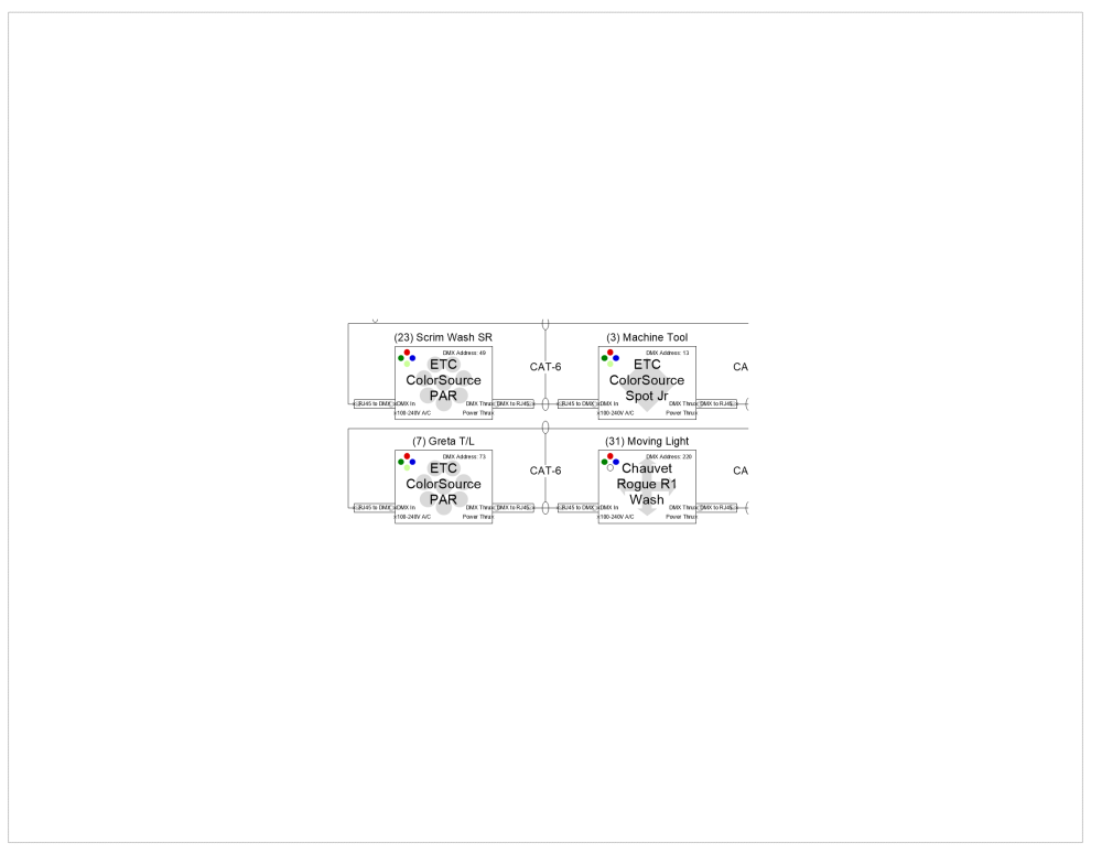
@lcdaI wrote a script a while back that does just this. It will build a viewport with matching visibilities as the active view and the with the scale of the active layer and creates a crop based on the bounding box of the selected items. It also has an option to center the viewport on the page after its constructed. Selected Objects and Dialog Box: Created Viewport on Page: To install the plug-in, download the attached .vsm file and place it in the Plug-ins folder of your User Folder (easiest way to get to this is to go to Vectorworks Preferences - User Folder and click on the Explore or Open in Finder button). Restart Vectorworks and then add it to your workspace by going to Tools - Workspaces - Edit Current Workspace. This will open up a dialog box with two large boxes side-by-side. Make sure the Menus tab is active, then in the left box, find and expand the category JNC, the script Create VP from Selection should be in there. In the box on the right, find a menu for the command to live in (such as the View menu). Then, click and drag the plug-in from the box on the left to the target menu in the box on the right. Then click OK. Create VP from Selection.vsm
-
You could include the texture file in a .vwx file in the plugin folder, then use FindFile or FindFileInPluginFolder to get a path to the file. From there, you would use BuildResourceListN with that path and type 93 to retrieve the textures in that .vwx file. You would then use ImportResourceToCurrentFile to import the necessary texture into the active file.