


JustinVH
-
Posts
591 -
Joined
-
Last visited
Content Type
Profiles
Forums
Events
Articles
Marionette
Store
Posts posted by JustinVH
-
-
Those were made using NURBS to create the choked section and then simple NURBS lines with curves to go under the truss and connect at the top. The trick is to do each component at its own NURBS piece and then compose them together before doing the extrude along path command. For that particular example you show I had one choke section as a NURBS curve that wrapped all around the chord, I had a second curve that connected to the end of the wrap and then under the truss to the midpoint, and the third was a curve that connected to the top of the choke and met where the shackle connects but only to the midline. I then composed those three lines together into into 1/4 of the entire NURBS curve and then mirrored to get 4 total sections. After performing an extrude along path with each section I them combined with the Solid Addition command. If you would like I can send you the template file with the curves already made and then you just have to manipulate and compose to your desired look.
-
 3
3
-
-
To add to Jesse's response, that 3D loci must be at (0,0,Z) or there is a risk that the parts of the light will explode in all different directions from the origin when trying to focus. This is why there are some lights where the yoke is a a wonky angle because we had to keep the loci centered but the yoke geometry was offset before turning vertical. That loci should also have the Parts record attached and be assigned Point.
-
To all concerned. This has been fixed and will be released in the Update 4 catalog rebuild in the English International version of VW2024. I am not sure of the exact date of Update 4 but wanted to let everyone know this has been fixed when that update goes live.
-
2
-
-
To model the look of the chain going over the block I would take two chain link symbols(in the symbol parts folder of the hoists) and connect them together with one rotated so it resembles chain in real life. I would then draw the path around the block using a NURBS curve and use the Duplicate Along Path command to add all the pairs of links together. Just make sure to duplicate by fixed distance which would be link to link and make sure to choose the Tangent option so everything rotates nicely.
-
2
-
-
You can cheat drawing lines of bicycle rack using the fence tool with a workaround. You just have to convert the fence to unstyled and choose the Infill in the dialog as the Infill Barrier Movable symbol which is bicycle rack and remove all the posts from the settings, set the spacing to the length of the bicycle rack and set all the heights to zero in the settings. Once the fence object is inserted you have to Cmd+K to convert the fence into a group so you can delete the posts that insert by default. I just did this and inserted over 200' of bicycle rack in under 30 seconds.
-
1
-
-
Kevin is correct.
-
Your request has been entered into the internal tracking system and has been assigned ticket number CD-4693. If that number is provided to Tech Support the representative will be able to provide a status update if there is one available.
-
Thank you for the request. This has been entered into our internal tracking system with ticket number CD-4692. If necessary, you can reach out to Tech Support and provide the listed number and the representative will be able to provide an update if one is available.
-
Your request has been added to the internal tracking system with a reference number of CD-4669. If desired, tech support can be contacted and given the reference number and can provide a status if available.
-
1
-
-
Try this course from Vectorworks University. It shows how to take the DWG files from a manufacturer and make it into a truss symbol as well as setup the truss in the Truss Properties dialog to allow for proper auto connect.
https://university.vectorworks.net/mod/overview/view.php?id=4325
-
1
-
-
3 minutes ago, LenLindhout said:
Now it smoothly calculates all 112tons of equipment in a heartbeat
That is a lot of equipment!
-
 1
1
-
-
In your VW2023 screenshots is that a corner block where the hoist is attached? If so, I don't believe you can have a corner block without the adjacent piece of truss attached but @jcogdell or @Scott C. Parkermay know better.
-
@gangottiPlease make a new request for the item that you are requesting so that other users can upvote the post. Once that is done I will enter the item into our internal tracking system and post the ticket number.
-
Thank you for the clarification. Your notes have been added to the above ticket number in our system.
-
1
-
-
@jcogdellCan you think of a way this can be done? I know that you helped and made some custom bridle objects for the default content a couple of versions ago.
-
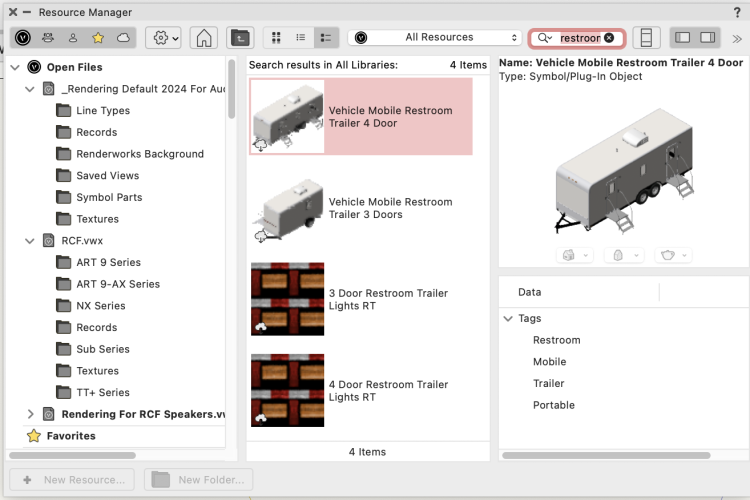
@AndrewYVR @jschulmanI did a quick search or the RM by typing in restroom into the search field and returned two results for portable restrooms for events. There is a screenshot attached. All that is needed for inventory reporting is to add the EntEquipUniversal record to the symbol container and populate the fields to your liking.
For those who want to track this request the ticket in JIRA(our internal tracking system) is CD-4672. If you reach out to Vectorworks Tech Support give the CD# they can give an update on what is currently listed for the development of this issue and a possible release date. Of course, that could change depending on other factors.
-
1
-
-
The existing slings in the libraries were made using a series of NURBS curves composed together and then the profile of the sling was extruded along the composed NURBS curve using the Extrude Along Path command.
-
3
-
-
I use a Bluetooth number pad and have it to the left of my keyboard. I am right handed but do all my view changes and number data entry on the Floating Data Tab with my left hand. I never take my right hand off the mouse and have reconfigured all my keyboard shortcuts that use more than just a single key to be left handed only.
-
3
-
-
Your request has been received and has been entered into our tracking system. The speakers will be released in a future update to the Vectorworks Premium Libraries. The ticket number in our system is CD-4649.
-
Your request has been received and has been entered into our internal tracking system for scheduling. The ticket ID is CD-4644.
-
1
-
-
Also make sure to refresh your Resource Manager from the gear icon to force the program to update the RM and get the latest from the cloud.
-
1
-
-
If the K3 bumpers are not in the Resource Manager then you should submit a request and start a new thread in this portion of the forum. This way the request can be upvoted by other users and help us with priority listing and planning.
-
1
-
-
There are actually two occurrences of the Truss Record. There is the occurrence attached to the symbol in the Resource Manager and there is the occurrence attached to the symbol once it is placed into your drawing on the design layer. Each symbol instance will allow you to change what is in the Truss Record(through the OIP) but this will not change the record of the symbol in the Resource Manager. In order to make the color changes stick you must change the Truss Record that is attached to the symbol in the RM, not the instances in the drawing on the design layer.
To do this, right click on the truss symbol in the RM and choose Edit 2D Component or Edit 3D Component(the choice is yours) and this will enter the symbol edit mode. Once in edit mode make sure nothing is selected and find the Truss Record in the Data pane of the OIP. Change the color in this location and then exit the symbol by clicking the Exit Symbol button on the top right. This will set the changes to the Truss Record and will allow the correct color choice to translate to reports and will allow the truss to be imported into other drawings and retain the color choice change. A good idea is to place this new truss into your User Libraries or Workgroup folder so that you will still have the changed truss when there are RM updates or when you open a new drawing.
-
2
-
-
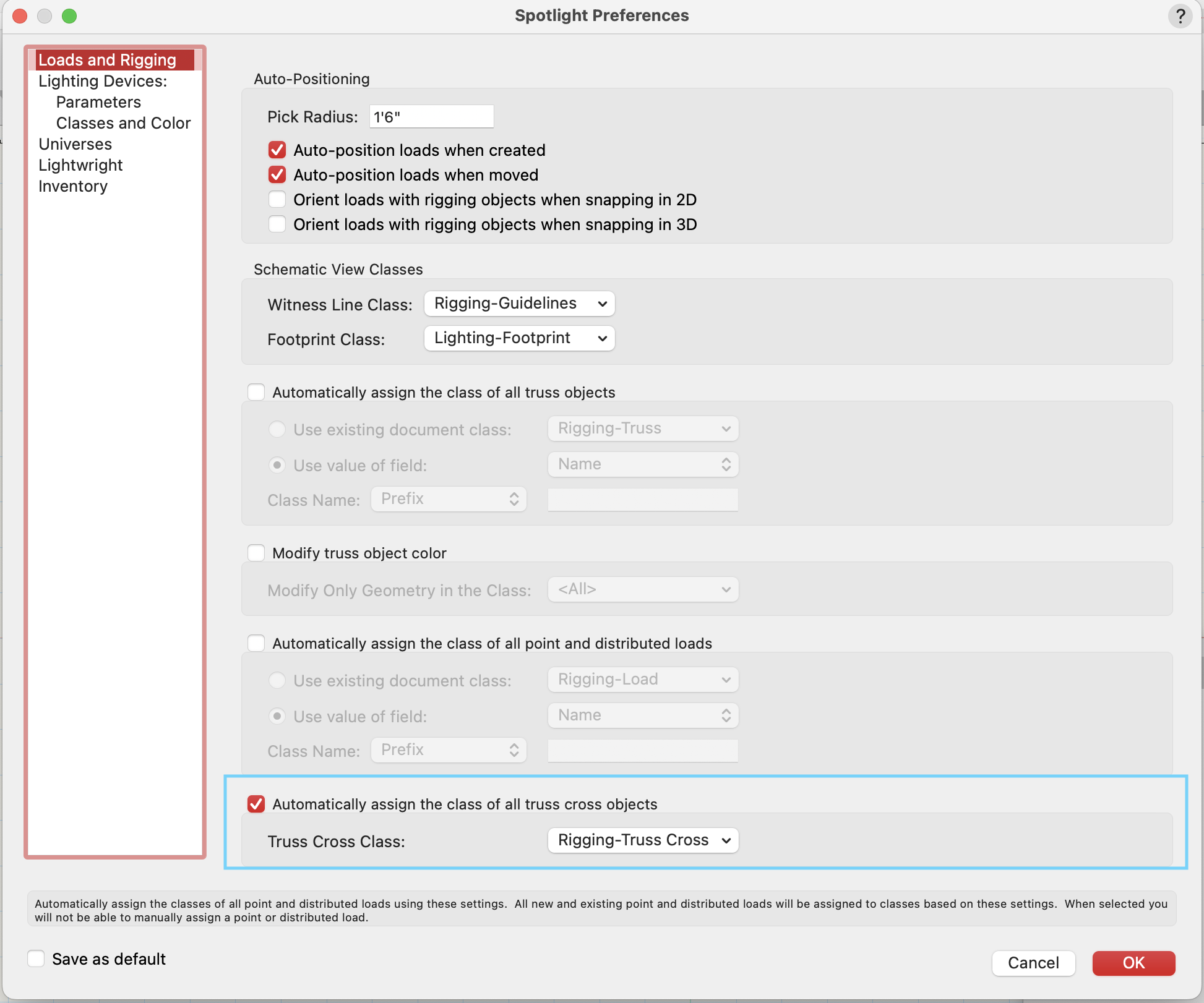
In the Spotlight Preferences there is an option to assign truss cross objects to a certain class of your choosing. This is off by default and needs to be activated by the user. I was also mistaken, the default class is Rigging-Truss Cross not Rigging-Truss-Truss Cross.

-
1
-

Data and Hoists
in Entertainment
Posted
@BRSebbeYou need to have the symbol downloaded into your document before you can access any of the symbol edit commands. It does not need to be inserted into your drawing, but it does need to be in the Resource Manager of your working document, not on the cloud.