


JustinVH
-
Posts
588 -
Joined
-
Last visited
Content Type
Profiles
Forums
Events
Articles
Marionette
Store
Everything posted by JustinVH
-
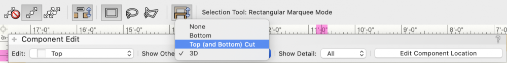
@trashcan A trick to help you align the 2D and 3D components of symbols is to make sure that while in the 2D component you enable the visibility of the 3D components. This allows you to draw right on top of the 3D and if your snaps are set correctly to snap to the 3D geometry. To enable the 3D visibility just make sure to show 3D in the "Show Other" dropdown in the Component Edit palette.
-
@Charlie Winter The only thing that I have found successful is to find the center of the base in Top/Plan with and place a 3D loci on this location. Then in a side view measure how far the 3D loci is from the beginning of the truss and then move both the the 2D and 3D in the base symbol by the appropriate distance. I believe the truss base symbol insertion point wants to be half the size of the truss box to the left of the center of the base. If you want me to check your file just let me know but I rarely get it right when I make the default content libraries so I just go into a side view and find the measurement and make the move. Justin
-
I agree with Scott. Definitely want to start with the base and build up and across. Also want to make sure that the base is set to vertical and the start connection is set to "No Connnection" so that the truss can only build in the up direction.
-
@trashcan Are these Vectorworks symbols or custom symbols? If you send me your file I can see what is the issue.
-
There are some truss pickups in the Vectorworks Libraries>Objects-Ent Truss>Truss Pickups folder in the Resource Manager. However, at this time they are setup as static rigging accessories and have no Braceworks or Auto Connect functionality.
-
Have you tried opening the gear icon at the top of the RM and choosing 'Refresh Libraries'? This usually solves that issue.
-
@Vesa There are also some tents in the content in the Resource Manger, they are located in the Vectorworks Libraries> Objects-Ent Event>Event Tents folder.
-

no definition in truss when Importing into MA 3D
JustinVH replied to JetSet86's question in Troubleshooting
Thank you for sending your file by DM. I have downloaded your file and sent you a response. -
no definition in truss when Importing into MA 3D
JustinVH replied to JetSet86's question in Troubleshooting
@JetSet86 What format are you using to bring the truss into MA3D? I would like to file a bug for the engineers to take a look? -
no definition in truss when Importing into MA 3D
JustinVH replied to JetSet86's question in Troubleshooting
Have you turned off the Rigging-Truss-Simplified class? It looks like that class is still on as it is just extruded an extruded rectangle. -
In content development world we have learned that simple objects like sweeps and extrudes should stay as sweeps and extrudes as converting to generic solids can sometimes increase the size of the object and symbol. Once we start performing operations like subtractions, additions, and commands from the 3D modeling tool set we convert to generic solids to strip the object of geometry history and reduce the file size. That being said, we always keep a backup copy of our files in non generic solids just in case a file corruption happens in the future and we need to examine the original symbol's creation methods.
-
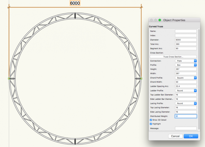
@jkamst Currently the Prolyte H30V circles do not exist in the libraries. With the recent acquisition of Prolyte by Area 4 Industries I will not be able to get a contact that I can request CAD files from in order to add to the existing Prolyte libraries. Unfortunately, at this time I cannot offer any sort of timeframe for additional content to the Prolyte libraries. I was able to make a complete 6 meter outside diameter circle using the Curved Truss tool and was Abel to set the cross section to Prolyte H30V. I have attached a screenshot of the settings I used with the tool and hopefully you are able to use similar settings to make the 2,4, and 6 meter circles that you desire. I am most likely wrong on the diameters of the lacing and ladder bars but those specs should be able to be found on the Prolyte website. Also note that my units are in mm so that is why my circle is 6000 in diameter and not 6. Let me know if you have any questions and feel free to DM me if needed.
-
@AlexSawaya Are you able to post a file? I can take a look at it and see if I can discover anything on Monday.
-
@AlexSawaya I took a look on my machine as well and it looks like what you are seeing are the loci for the Braceworks-Distributed Load class. This is added to the cables and other items so that the weights can be used to properly calculate all weights in Braceworks. If you turn off the Braceworks-Distributed Load class the loci will disappear and the line will be thin again. I am going to file a bug for this today.
-
Those marks appear to be 2D loci. Have you contacted tech support regarding this? That may be a bug that nobody is aware of yet.
-
@livespace josha I would avoid duplicating individual pieces of truss or corners and trying to place them. Sometimes this causes issues with the auto connect and introducing artifacts. I always go back to the resource manager and grab a new piece of truss much like you would when onsite and you have to go back to the truck or to the pile in the arena to get another piece. If you are making a run of 100' using 10' sections you can simply keep the symbol active and use auto connect to snap across and you don't have to keep selecting from the resource manager. The "Make Active" command at 0:13 is how I activate all symbols from the resource manager. Simply choose your symbol in the resource manager and right click to open a menu and make active will be there. It will activate the symbol as a parametric object and you won't have to use the resource picker like you do if you use a tool. You can also double click to activate a symbol as a parametric object as well.
-
What Vectorworks version are you using?
-
@livespace josha Are you able to send me this file by DM so that I can take a look? I setup the auto connect settings for all of the truss that is shipped in the Resource Manager and I have not experienced this type of behavior that you are showing. Are those Christie Lites Type A symbols or some other manufacturer? If they are Christie Lites Type A part of the issue you are having has to do with the corner and the gusset plates. The gusset plates actually lie outside the "box" of the straight truss and because of how the 3D symbol for the corner is laid out the corner shifts by 3/8" when snapping using auto connect. In plan view the corner block and upright are not perfectly aligned like the real world and the auto connect is having trouble finding the side snap points. If you are able to send the file I would love to take a look and see what else could be causing the issue and see if I can fix it in your file and send it back to you or find the cause and file a bug. I made a quick video using Christie Lites Type A 6 way corner block and a 8' straight piece of truss to assemble a goal post and the auto connect worked as I would expect but I had to use right or left isometric views as I find they help when assembling truss vertically. When I tried to connect from a top view I did also have the struggles that are present in your video. Truss Corners.mov
-
@Wade You should make sure that you save a copy of your modified .txt files somewhere on your desktop as well. When Vectorworks gets updated through service packs or new releases the .txt files that are in the installer may override your custom changes and you will have to do the work again to modify your signals and connectors. I am not saying this will happen but just wanted to give you a heads up so you don't risk losing your work and can just replace the .txt file quickly.
-
@a guy Is there any way that you can DM me the engineering data for the truss and I can take a look. I just create the geometry and setup the auto connect information. The Braceworks information is setup by our structural engineer and then coded into the software. I may be able to decipher though if you send it to me, no promises though.
-
@Peter Neufeld You are correct. The only way to change the cross section is throughTruss Properties page by right clicking on a truss symbol.
-
Rotation of symbols in resource browser...
JustinVH replied to anthall5's topic in General Discussion
@anthall5 Not a problem to help you. Litec was released in the September and November 2019 updates to the Service Select libraries. Most of their products are in the software now but still need the Braceworks data for calculations. They can be found in the Service Select Libraries>Objects-Ent Truss>Litec folder and you can use those as a guide for setting your symbols up or modify them to your style. The DADO connectors are in there as well to use as a guide. They are setup just like corners but you have to make them X-Corners and so some crazy math. You can DM me if after looking at the existing libraries you still need some help. I have attached a screenshot of the Litec libraries in the RM for you.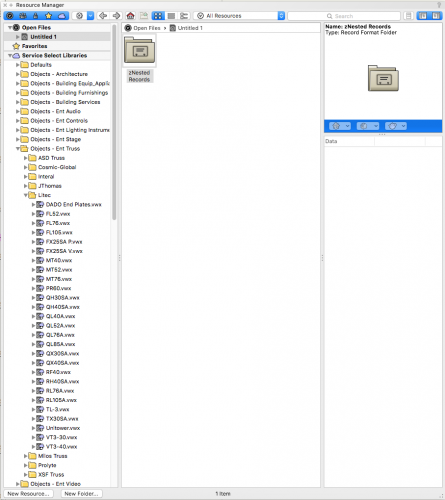
-
Rotation of symbols in resource browser...
JustinVH replied to anthall5's topic in General Discussion
@anthall5 If you need any assistance making those symbols into fully functional truss symbols with auto connect please let me know. I build and setup most of the truss that ships in the default content so I would be glad to answer any questions you have. Those look like Litec truss which is also not included in the Vectorworks Service Select libraries if you are a member of this program. I know that Litec is working on getting us the Braceworks data as well so at some point in the future you may be able to connect your custom symbols to a Braceworks cross section and have full functionality. -
@stayathomedad Are you talking about the auto connect cross that is in the end and in the middle of each truss symbol or are you talking about the Insert Points loci?
-
@Zach Are you using VW2019 or VW2020? Those items should have been fixed for 2020?


