


JustinVH
-
Posts
591 -
Joined
-
Last visited
Content Type
Profiles
Forums
Events
Articles
Marionette
Store
Posts posted by JustinVH
-
-
@BNULB Are you talking about the Auto Connect function? The 2D and 3D loci are remnants of the truss symbols before the Auto Connect feature was added to the software. It sounds like the QX30 is a Litec corner. Is is possible to share a screenshot or the file so that I can see what type of corner this is so I can provide the best help? Without knowing the configuration of this corner I don't know which technique for determining the snap locations to show.
-
@Mark Aceto A trick that I found with the Pickup Symbol is to change the classing of the 2D geometry so that you can turn it off by class but leave the 3D visible with the OIP. Both the 2D and 3D are on the Rigging-Truss-Accessories class by default.
-
 2
2
-
-
@Cookie_NZ You can pre-add clamps to lighting devices. Just be sure to have the parts record attached to the clamp and set to 'Base' and also have the Light Info Record attached to the clamp and choose Accessory or Static Accessory for the Device Type.
-
1
-
-
@MartinBlomberg Is it posible to send me the file so that I can take a look?
-
@EskiVES If you are running Vectorworks 2019 the Layher scaffolding is in the Vectorworks Service Select Libraries for that release in the Objects>Ent Stage folder.
-
@Mark Aceto Can you DM me the file so I can look?
-
@Mark Aceto Here you go. In order to get things to line up correctly I performed the following steps:
-Align the 3D geometry so that the center of the clamp is centered on the pipe.
-If you want to show two clamps have two instances of the 3D geometry in clamp symbol.
-Exit the symbol and attach the Parts record to the symbol.
-Choose Base to be true for the symbol.
-Use the accessory tool to insert the clamp.
-
2
-
-
Unfortunately, I do not have a possible solution for you. Tech support may be your best bet.
-
@michael john williams Are you using VW2021? In the Document Preferences there is a new feature called 'Save VGM Cache'. This is on by default and can cause the file size to increase. Turning that cache off should help to reduce the file size but will make file opening and navigating slower. I hope that helps.
-
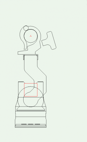
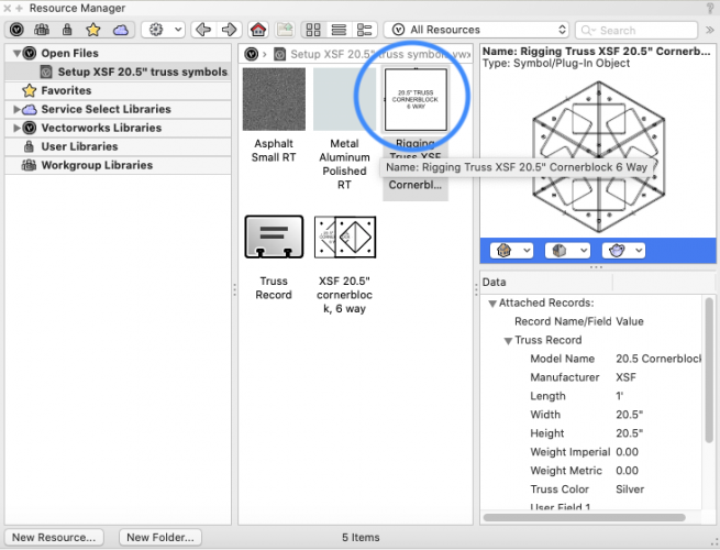
@wadecordts I downloaded your file and set the corner up for you using the proper truss record and the auto connect settings that should apply to corner blocks. Without having a piece of straight truss to connect to the corner it is hard to confirm is all the settings are correct but testing using the corner appears looks right. I left your original symbol but duplicated it and drew it again to setup with the naming that would be used if I released this myself in the shipped VSS libraries. Use the symbol I circled in the screenshot as that is the setup symbol. If you have any questions or issues please DM me and I will be glad to help.
Justin
-
@Mark Aceto Those wire rope "stingers" are not in the content at this time. My recommendation is if you would like to add steel to the pickup symbol to duplicate the symbol and add the length of steel you desire as geometry. Just remember to change the offset in the SlingRecord and add the additional weight in grams.
-
@Mark Aceto The 3D loci in the shackle is from the zNested shackle that lives with the new pickup symbols. They live on the NonPlot class and are there to take measurements from the pin and the apex of the bell(mainly put there by me to set the heights and insertion points of all those new symbols) when in wireframe. That is why the new hoist hook also has a 3D loci.
The sling offset is measuring the distance from the center of the truss (that auto connect cross that cannot be hidden) to the top of the inside of the bell in the shackle, of course if the pin is up then that measurement is to the bottom of the pin where the next rigging point will connect. Keep in mind this measurement must be in mm due to the code of the record and I like to use 3 decimal places even though the field is set to use 1 place. The loci are on the NonPlot class so they can be turned off by the user.
-
1
-
-
- Popular Post
- Popular Post
10 hours ago, Mark Aceto said:
And now all of the truss symbols in the RM are displayed in mm lol... Hey, is there a ways to change that?@Mark Aceto The reason they are all in mm is because the code is in metric and all of our internal scripts for setting up the data are in metric. It makes it easier if both of the spreadsheets that are used for setup are using the same units and that is why the record in the RM is in mm even though the truss properties will use document units. However, an experiment was conducted late last year and it was determined that the RM record could be Imperial as long as the spreadsheet to setup the Braceworks part of the symbol was in metric. As a result, we made a change and decided to ship US manufacturers with Imperial units in the RM record and European, UK, and Australian companies with metric units for all future releases. You can see this change in some of the later XSF libraries and some of the new James Thomas and Tomcat libraries in 2021as they were released in the 2020 version after the decision was made. As new truss libraries are released you will see the preferred units for the country of use/manufacturer in the RM.
-
4
-
 1
1
-
@Alexey Trebukhin I have found that if you go into the OIP and choose 'Edit Accessories' you can then add additional clamps. You want to be sure to use the second mode though so that the extra clamps do not insert at the insertion point of the symbol but instead where you click them into the document. You may also have to go into a front or side view and adjust the clamp height to line up with the bottom of the base.
If you make a custom symbol and add an additional clamp so that two attach in one symbol you will need to update the weight of the symbol.
-
@MattG Here is a file. Please note that the weight may not be exactly correct. If you want to change it note that weight is in grams and offset length is in mm.
-
1
-
-
@Mark Aceto What is the width of the Tyler GT? Could the placement of the appropriate symbol in the Pickups folder be altered to work? I know it is not a sling but at least it is a pickup symbol.
-
1
-
-
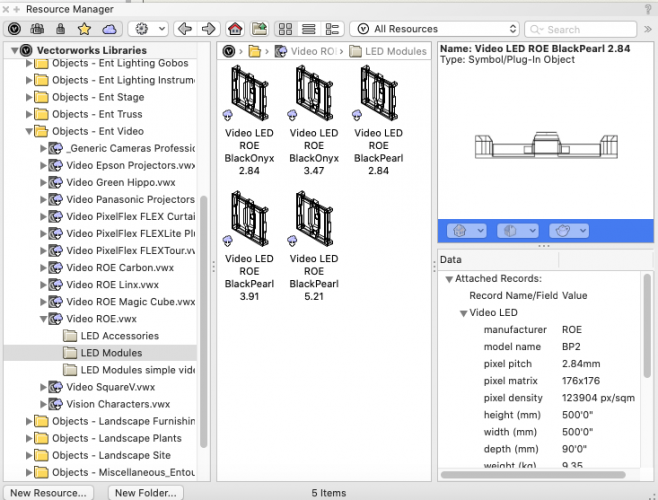
@Jacobtheld If you are using Vectorworks 2020 the Roe BP2 is available in the Resource Manager in the Vectorworks Libraries>Objects Ent Video>Video ROE file.
-
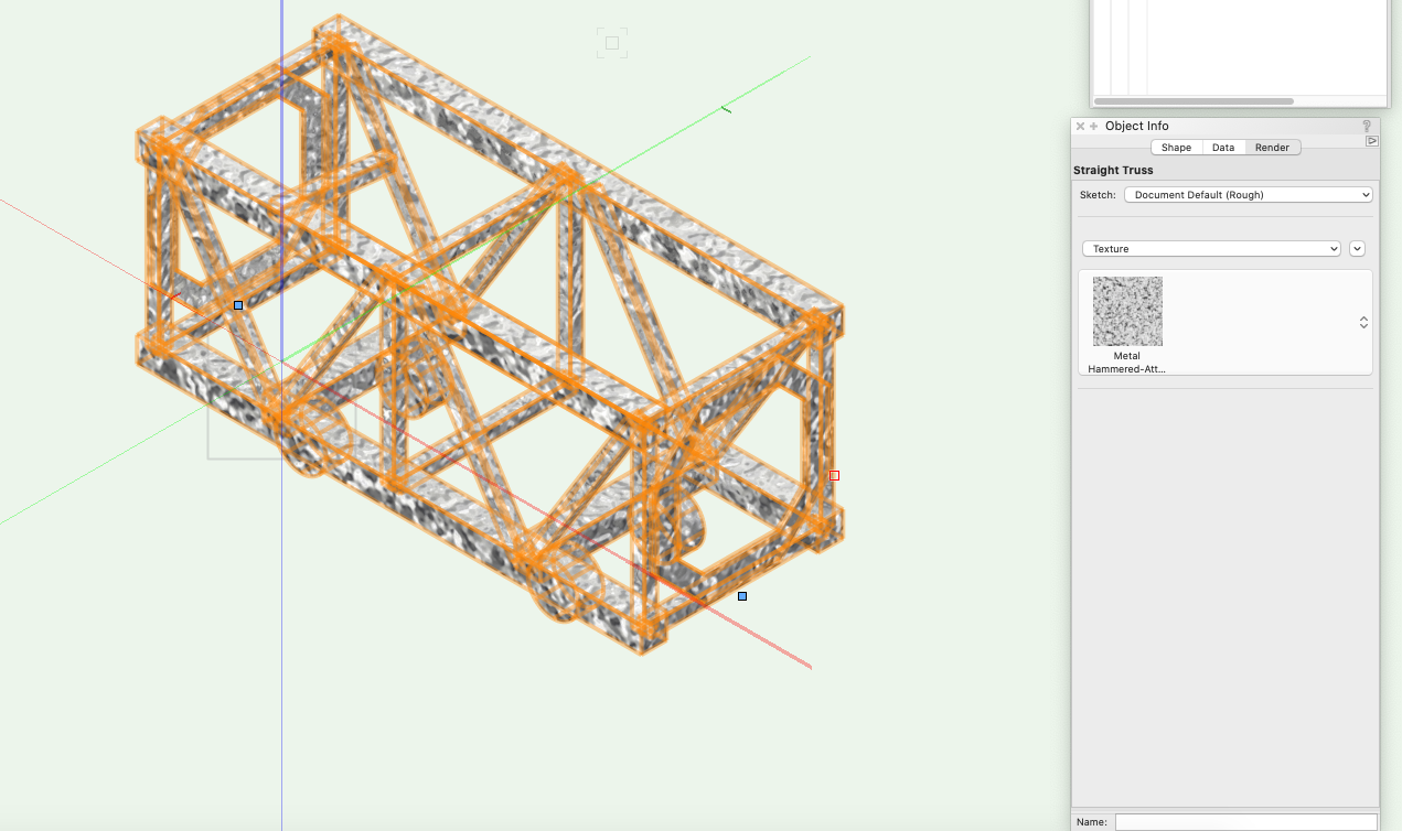
I believe the issue with not being able to apply a texture has been resolved. I was able to apply a texture using the render tab of the OIP using VW 2020 SP4.

-
1
-
-
@Haydenovative Not sure how to change the 3D fill as the geometry is generated from using the tool but you can assign a texture using the render tab of the OIP and choosing the texture that you desire. In my test I downloaded the Chrome texture and applied it successfully for renders.
-
1
-
-
@gmulder I took a look and I was able to fix your file and come up with a solution. The trick is to use the No Connection option on the flat base portion of the truss base when when setting up the truss info. Using the No Connection option will force the Auto Connect Engine to only use the Neutral, Male, or Female end of the symbol which will flip the symbol accordingly when placing on top of a piece of truss, this way you only need to have one symbol that can be used on both ends. In the file I have attached I set your base as a "No Connection" start and a "Male" end connection and the corresponding test piece of truss as a "Female" connection for both start and end. I did this as I saw you were using the gendered connections and decided to stick with that for you.
Typically the conical connections that are on the H30V line of truss use the "Neutral" connection in the libraries that ship with Vectorworks as a separate coupler is used in the real world and is not actually placed into the drawing. I typically only use Male/Female with the shipped libraries if the end connections are welded onto the truss at the factory like you see with fork and gable style truss. I also tested with using "Neutral" on the truss and male portion of the base plate and also had success in getting the plate to properly connect to the top of the truss. If you decide to use other shipped H30V content out the Resource Manager keep in mind these will be using the "Neutral" connection and you will have to adjust them to Female/Female to use the base in your file. Let me know if you have any further questions.
Justin
-
1
-
-
@gmulder I will take a look at this, I think I have a solution that will work for you. I will post the file here is I have success.
-
1
-
-
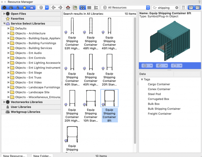
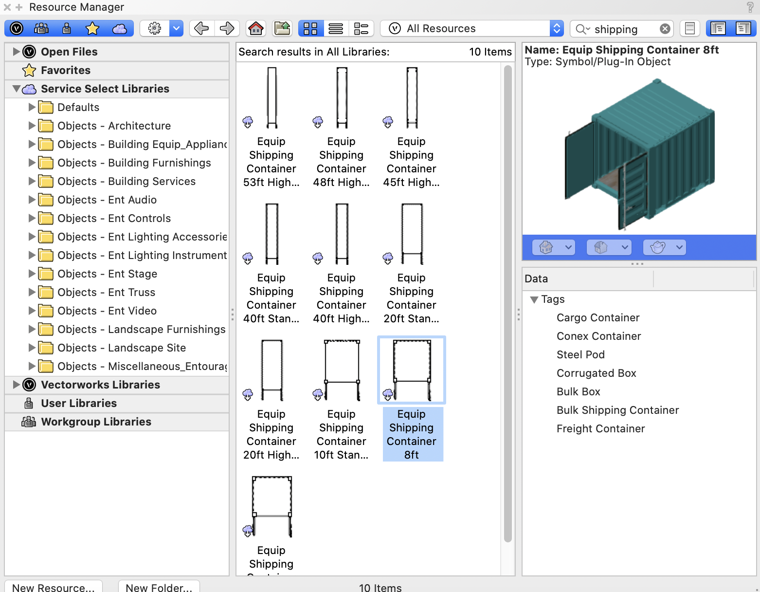
@trashcan There are shipping containers in the Resource Manager in the Objects-Landscape Site>Equipment Shipping Containers file. There are multiple sizes and they can be connected together to make different structures.
-
2
-
-
@MAURO I know it is not Marionette but if you have VSS the Litec Q30 product lines have been released as symbols and are available in the Resource Manager.
-
That is normal for truss. The insertion point of all of the truss in the Resource Manager is bottom center when viewed from the side. It just happens that triangle truss in the point down direction puts the insertion point on the chord and not in between the chords.


Creating snap points for truss corners
in Braceworks
Posted
@BNULB Even though you have the educational version you still should be able to use Auto Connect as that is a Spotlight/Designer feature. You won't be able to run calculations because that is what the Braceworks module adds to the software.
I took a look at your file and that DEDO symbol is from the VW libraries but it looks like you modified the 2D which is perfectly fine. Your particular instance in your document seems to have inserted as a 2D/3D symbol and not a Truss Object. I used your symbol and inserted it using the 'Insert Truss' from the Rigging toolset and was able to connect Litec QX30SA truss to all six locations. Let me know if you have any further questions but you are on the right track and it should work for you.