


JustinVH
-
Posts
591 -
Joined
-
Last visited
Content Type
Profiles
Forums
Events
Articles
Marionette
Store
Posts posted by JustinVH
-
-
@Iainy1961Is this what you were trying to achieve? It is still a lighting device for me.
-
@Iainy1961You will have to go into the Edit 2D Component of the symbol and redraw the 2D geometry in order to get the look you desire. To do this follow these steps:
-To access edit window, right click on the symbol in the RM and choose Edit 2D Component to enter the 2D Top/Plan geometry.
-Delete the current 2D geometry.
-Redraw your desired geometry and assign classes as appropriate.
A good trick to draw this view can be achieved using the cardinal direction 2D geometry that is used for Architect symbols but not supported for Spotlight. To do this trick do the following:
-Right click on the symbol in the RM and choose Edit 3D Component to enter the 3D Top/Plan geometry.
-In the Component Edit Palette choose Front from the Edit Dropdown.
-With nothing selected, right click in empty space and choose the Generate 2D from 3D Component command, and choose Hidden Line.
-The program will draw the view in 2D in a group.
-Copy or Cmd/Ctrl X to get the geometry on your clipboard.
-Return to the 2D Component and paste the group into the 2D, from there edit the line work as you see fit, sometimes the curves can be created as lots of tiny facets so you may want to clean up that line work.
-
 1
1
-
-
I may be wrong but I believe that the rendering engine used for Spotlight lighting instruments can only render a symmetrical round beam regardless of the beam and field angles. The Draw Beam option will take the beam and field angles into account for showing how the beam spreads but cannot be used to render. I believe you have to create a different type of lighting fixture and use an .ies file to get oval beams. I am adding @klinzey who will be able to clarify for certain if my statement is correct.
-
1
-
-
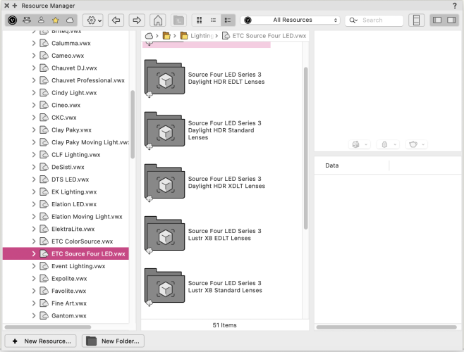
@Alex KeenThey are definitely there. They are in the Premium Libraries in the Lighting Instruments>ETC Source Four LED folder. You have to have access to Premium Libraries and have them enabled to see this content.
-
@mjmNot a problem. In fact, here is a file with just those two textures in case anyone wants to use them for their work. It saves the hassle of trying to search and find them as they can be buried.
-
1
-
-
There are also Default Instrument Textures in Silver and White that can be downloaded in the RM and applied to the lights. Keep in mind that the geometry of shipped symbols is set to Cool Gray 90% so if you render without textures turned on the light will still look like a black blob even if you lighten the texture so you may also want to change the color of the geometry. Almost 100%(well over 99%) of the lights in the shipped content libraries will use the Default Instrument Texture-Black with a color of Cool Gray 90% unless a manufacturer has a white or silver option and specifically asks for us to use one of the other default textures.
-
1
-
-
All you have to do is go into the 2D Component of the symbol and remove the circle and add the rectangle that you wish. You can class the rectangle as you desire and set your line weights. Doing so will not cause any issues with the functionality of the symbol. Vectorworks is not going to ship a changed version of the 2D geometry so this change will have to be made by the user if desired.
-
1
-
-
That is 100% Z-Fighting. Are you able to upload the file so someone can take a look at it? I would be curious to see whether it is the image geometry getting in the way or if it is the screen geometry itself getting in the way. Being able to examine the object will help everyone determine which piece of geometry to shift.
-
1
-
-
This request is currently being developed and is scheduled for release in the April 2024 Premium Library update in the English International version of VW2024.
-
This request is in production and is scheduled for delivery in the April 2024 Premium Library update in the English International version of VW2024.
-
Just letting everyone know that the initial four requests made by Mark on this thread are in production and are scheduled for the April 2024 Premium Library update in the English International version of VW2024. If anyone is using a language localized distributor version the inclusion of the April 2024 updated libraries may be delayed depending on that distributor's localization schedule.
-
@markddI believe you have made a really informative video on this? I do not know where the link is at the moment though.
-
Do you need it to function as a Spotlight lighting device or can it just function as a generic symbol? Knowing this answer can better determine if a solution exists.
-
1
-
-
Take a look at the at the Astera AX1 in the Resource Manager. They are similar and may be a good starting point if you need to model them yourself.
-
Anything that is prefixed Light Fixt is designed for Architect use and will be story aware. Anything prefixed Light Instr is designed for theatrical use and will not be story aware.
-
That lift was inserted using the Stage Lift tool which is located in the Rigging tool set.
-
1
-
-
- Popular Post
- Popular Post
The biggest issue with plumbing fixtures and a lot of architectural content is that those manufacturers don't want to work with Vectorworks because the other CAD softwares have larger market shares and are able to use DWG and Revit formats right out of the box. Those companies don't want to devote the resources to working with Vectorworks even though the CAD Content Team would be doing the clean up for them. Emails and phone calls are left unanswered or simply stated not interested. On the other hand, Entertainment companies are beating down the door to get added are willing to do the work for us or provide whatever we need to make the process as seamless as possible, this is also starting to be true for Landmark products as well which is why there are more of those symbols being added. We ask the user to hound the companies to work with Vectorworks so we can include their products as we feel that if many users complain there is a better chance of it happening.
-
5
-
Your request has been entered into the internal tracking system that is used in CAD Content Development. The issue number is CD-4780 and if you reach out to tech support and provide the tracking number they can give any status updates that are available.
-
Sorry, many people started Slacking me and I got disrupted. Here is a file with the T-Link set up to make a T-Corner. I ran a Braceworks calculation as well and it worked. The only tricky part is when you auto connect to the perpendicular portion you are hovering over empty space to find the auto-connect line but it can be found. I found it was easier to hover over the link itself or turn on the Insert Points class to find the loci.
-
It can be done. You just have to set it up like a T-Corner. I made this exact symbol as a special request for a huge touring company several years ago. If I can find it I will attach it here, I think it took me less than five minutes to duplicate the existing symbol and set it up to be a T and it did work with Braceworks.
-
2
-
-
What are the pendant lights that you are using?
-
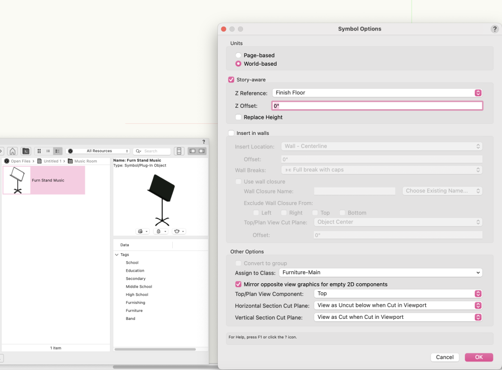
One more note, there is a music stand in the Entertainment folder that is not story aware by default. It is located in Entertainment>Stage>_Generic>Musical Instruments.
-
@echerneyThe music stand is set to story aware in the Symbol Options and that is why your height keeps changing. You can uncheck this option by right clicking on the symbol and editing the symbol options. I will log this in our internal tracking system and discuss with the team if this should really be story aware or not.


Editing a lighting symbol
in Entertainment
Posted
@Iainy1961You may have left the front 2D in that view. Those views are not supported in Spotlight Lighting Instruments. Glad that is what you are looking for though.