


Mat Caird
-
Posts
313 -
Joined
-
Last visited
Content Type
Profiles
Forums
Events
Articles
Marionette
Store
Posts posted by Mat Caird
-
-
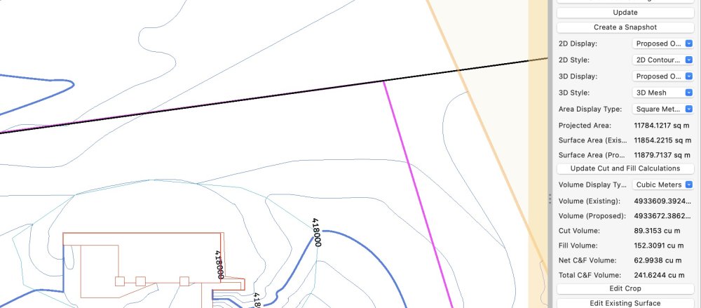
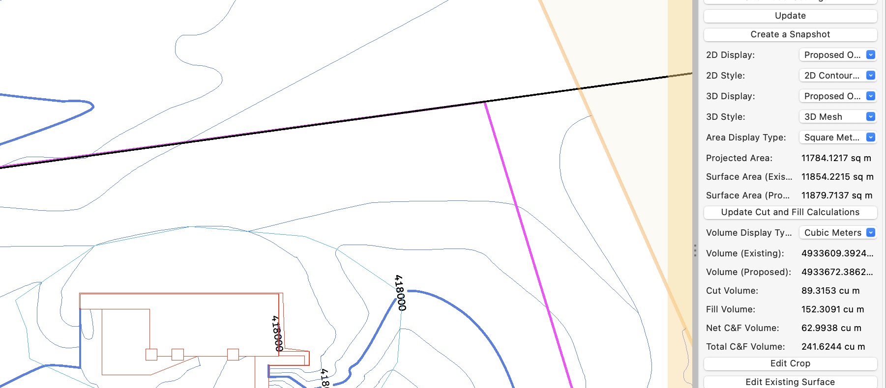
Thanks Michaelk, this worked a treat.
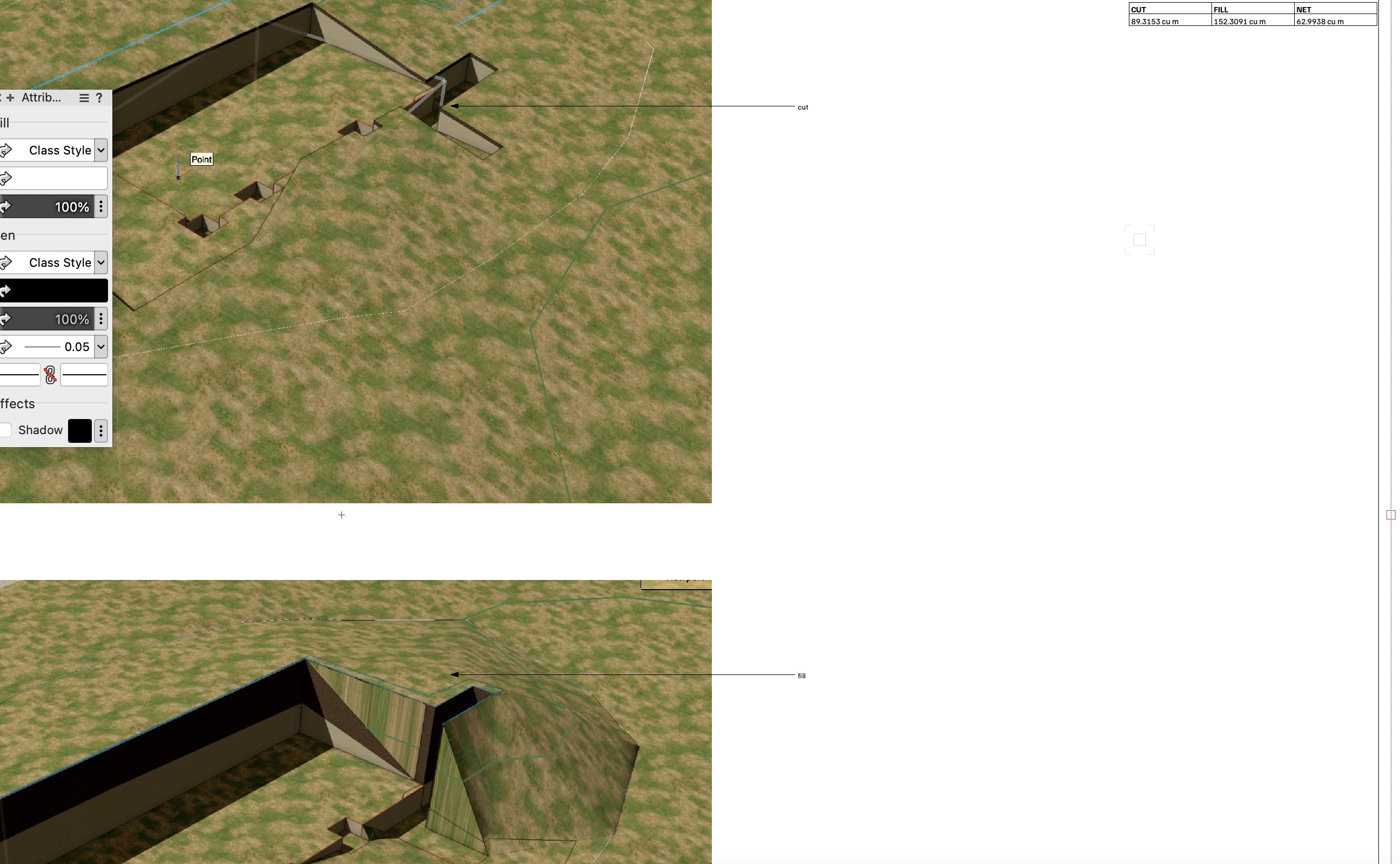
I used screenshots to show the cut and fill images.
The "Create a Snapshot" didn't work as I expected - when I deleted the Grade Limits Site modifier (ie the modifier responsible for the Fill), the snapshot changed.
I'd be interested in feedback on what the "Create a Snapshot" feature could be used for.
(There are some other steps I've ignored to keep my question concise).
Regards, Mat

-
Hi All
How do I get a simple cut and fill worksheet same as shows up in the OIP when the site model is selected?
I've tried the AEC|Terrain|Create Site model Volume List but the result is zero, even though the OIP shows the values.
Thanks in advance, Mat
-
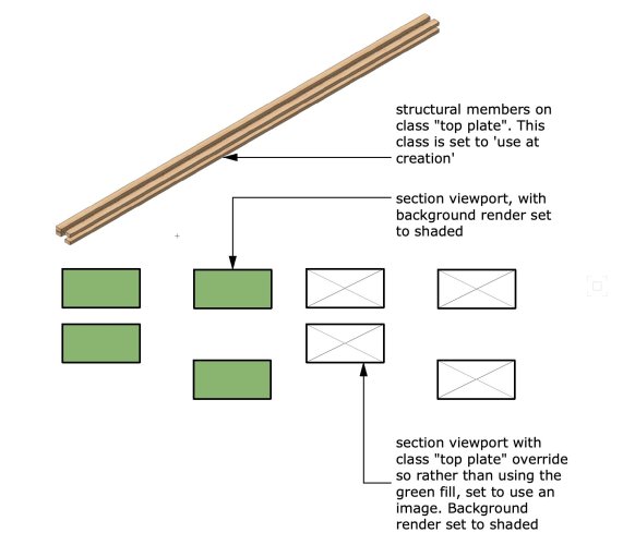
Create a class named Slab.
Set the line weight to be .18Tick the option for “use at creation”
select your slab and change its class to the new class Slab
choose yes when asked about assigning the new class options to existing objects.
now, in plan, your slab should have a line weight of .18
next, select the section viewport, then select Classes in the object info palette.
double click the slab class and now you can override the class appearance in this viewport only.
The key to making this work is that the slab object must be on a class that is set to use at creation, and the slab must not have any overrides applied to it via the Attributes palette.
I like to use a grey solid fill in the plan views, then override with a concrete hatch in the section VP
-
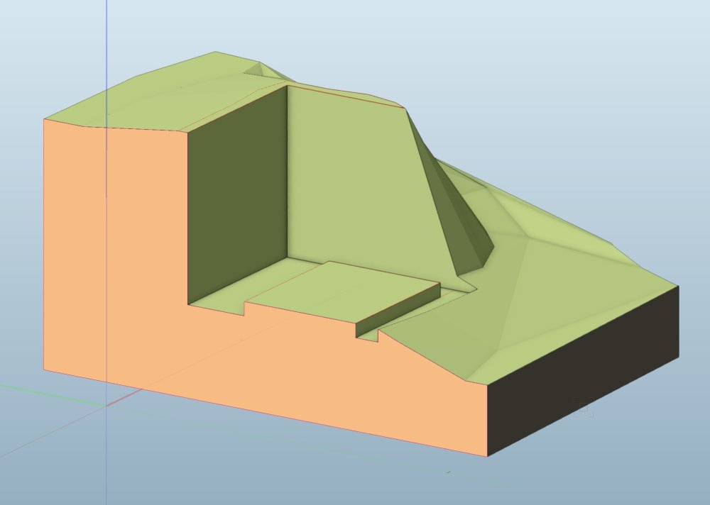
Hi Zoomer
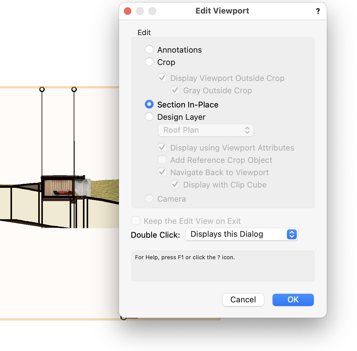
To display the fill;
Double click the section viewport, choose Edit | Section in place.
Orbit the view to suit.
In VW2023 you can rotate/orbit the view (I don't think this was possible in earlier versions of the edit section in place feature.)

Here's the test file showing the fill;
Still no lines.
-
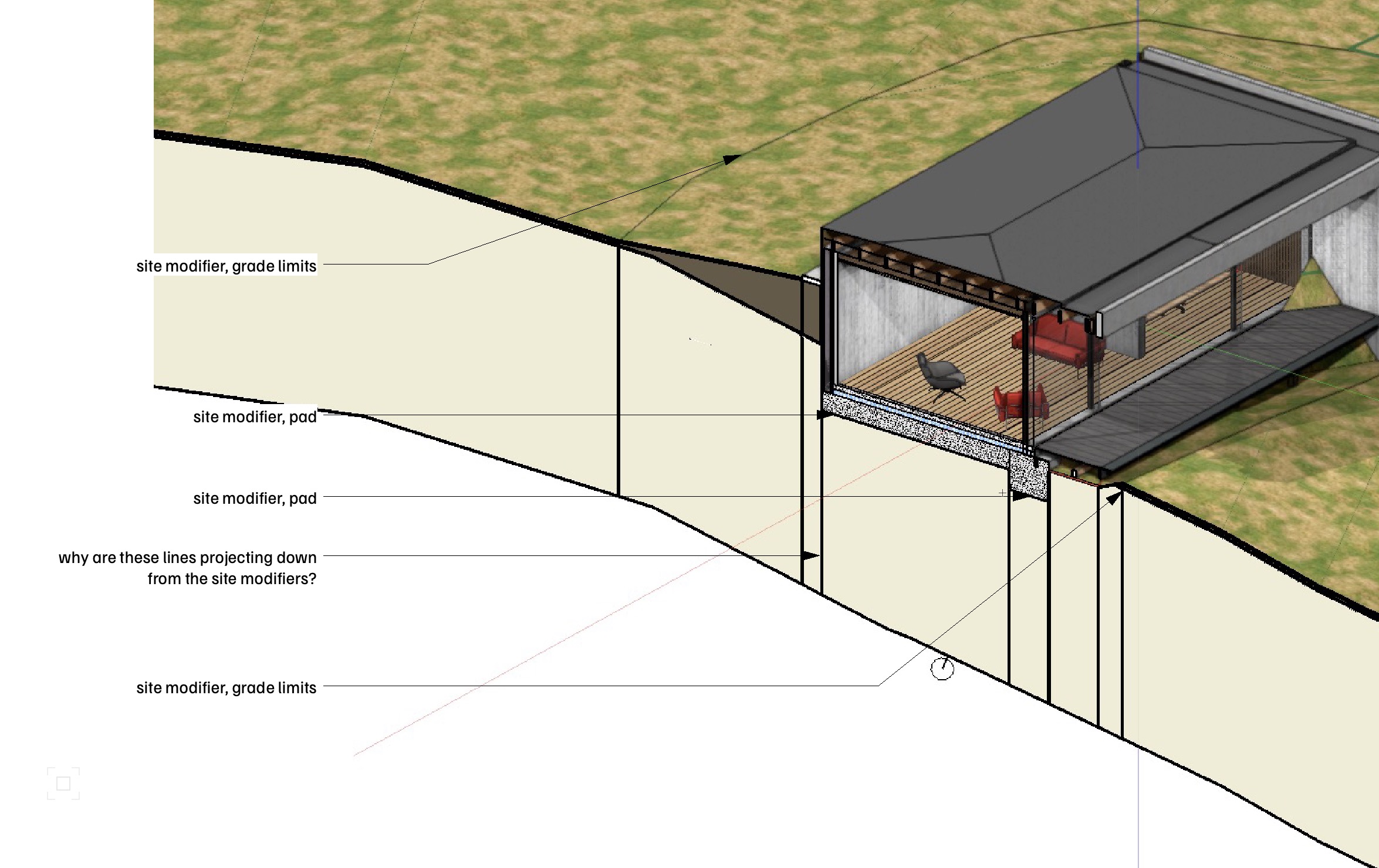
Hi All. Can anyone explain me how to remove these vertical lines on my site model please;
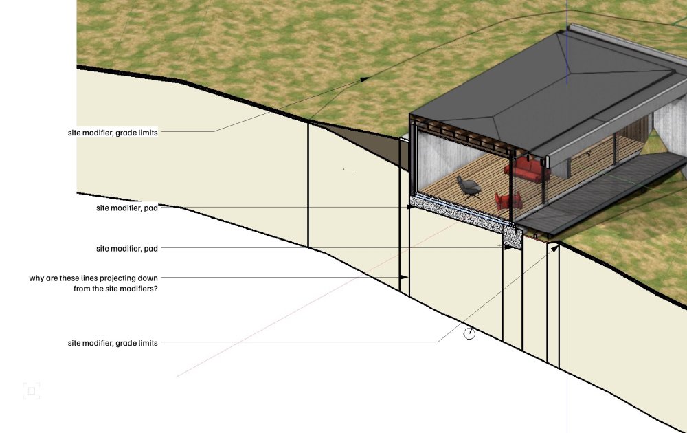
I've set up a test file, and the test file does not display the lines for some reason.

Thanks in advance all.
Mat
-
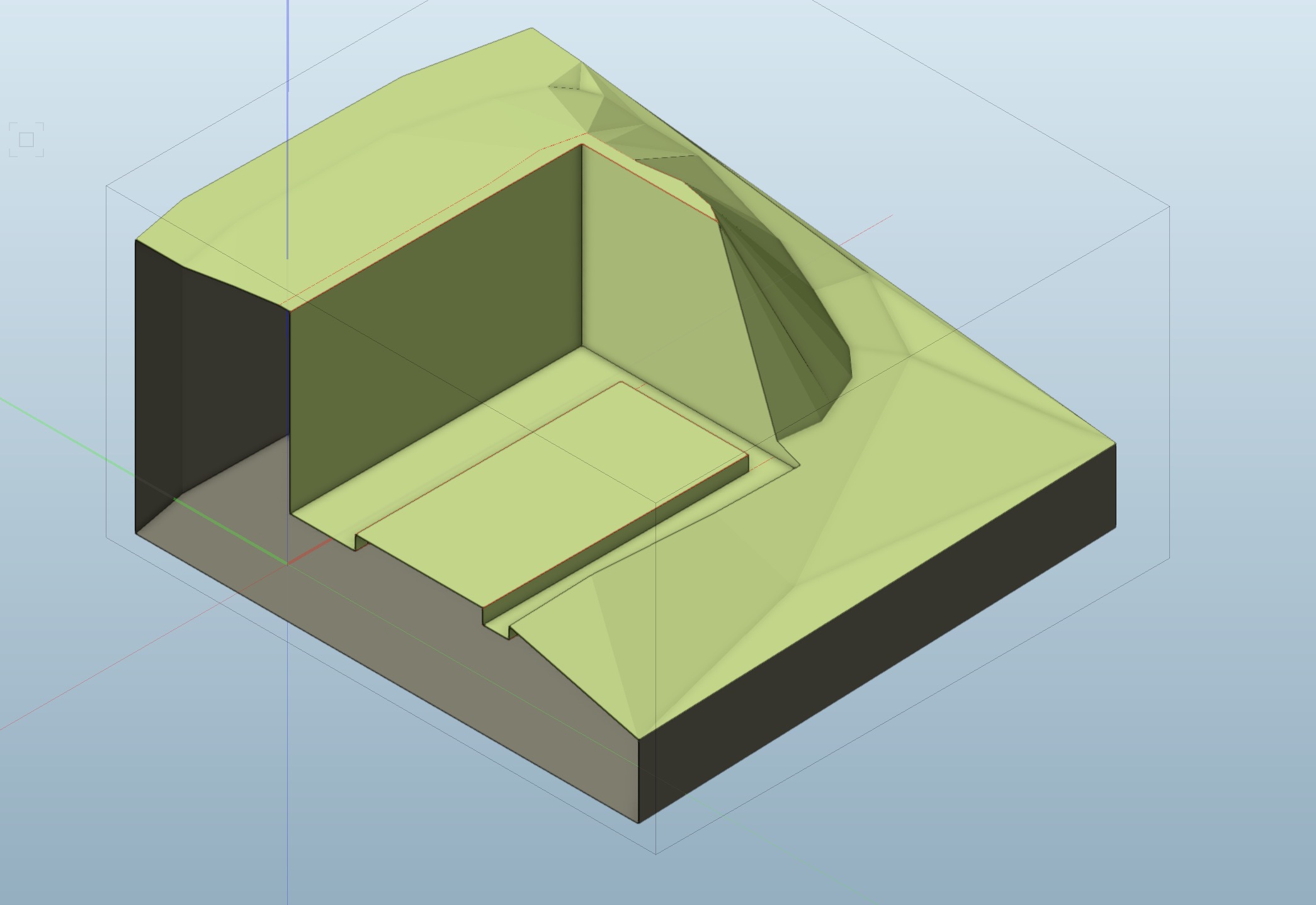
Thanks to Jonathon Pickup, I think I discovered the problem;
-
 1
1
-
-
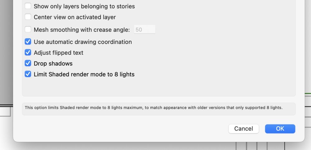
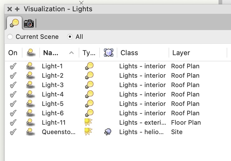
Hi Dave, yes they are. FWIW I use classes to control the visibility of lights rather than the vis. palette.
Thanks, Mat
-
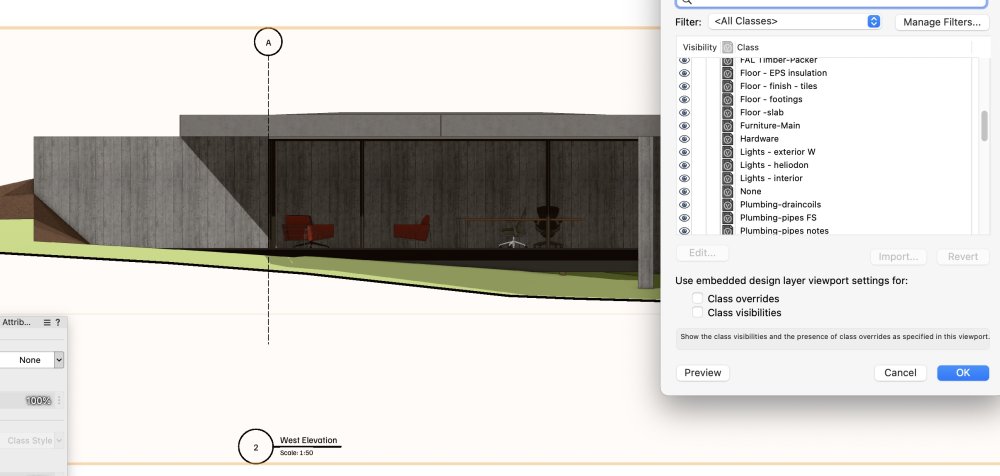
Hi All
I have 6 light objects used to illuminate the interior of my building. These lights are on their own class, and all the lights are set to 'on' in the OIP. They act as expected on the design layer as below;
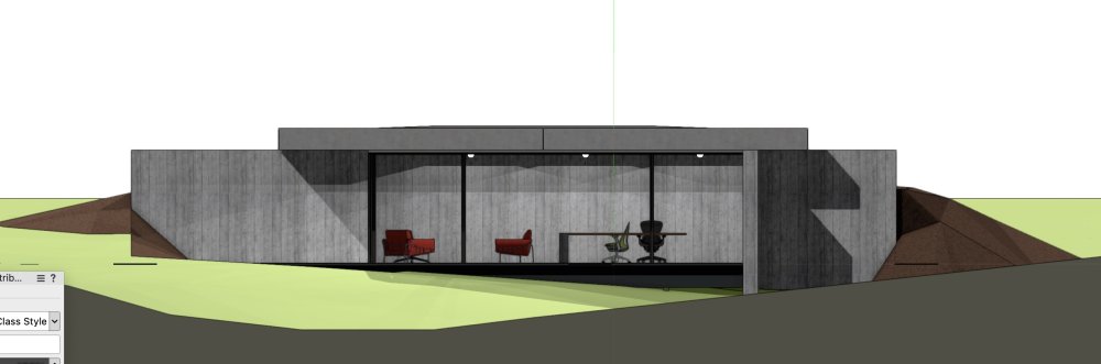
I have created a sheet layer viewport (below), and the lights sometimes work, and sometimes don't. I have tried deleting and redrawing the lights. I have tried switching them on and off in the OIP. I have checked classes and layers, and all seems correct. Any ideas anyone? TIA
-
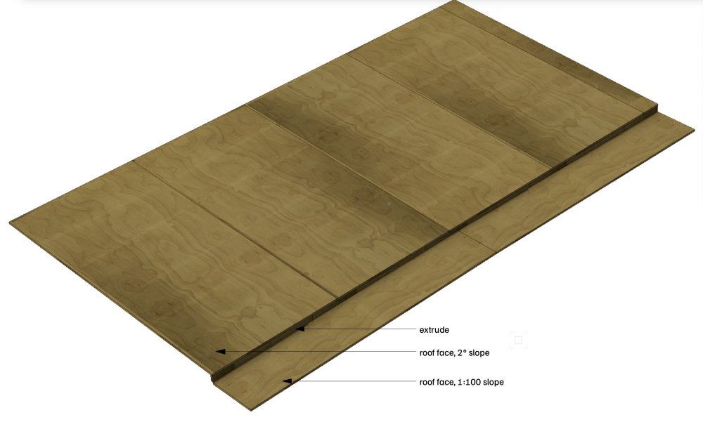
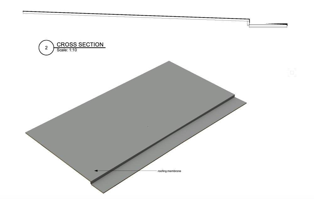
I always use roof faces for this kind of thing. Basically, I just model the plywood....
You can use the extract surface tool to quickly model the rubber membrane. You'll need to move it slightly so it sits above the plywood.
It will work OK in a cross section - I'd annotate the plywood in section with a plywood hatch I use.
You'd need to manually annotate the slopes per sheet.
-
1
-
-
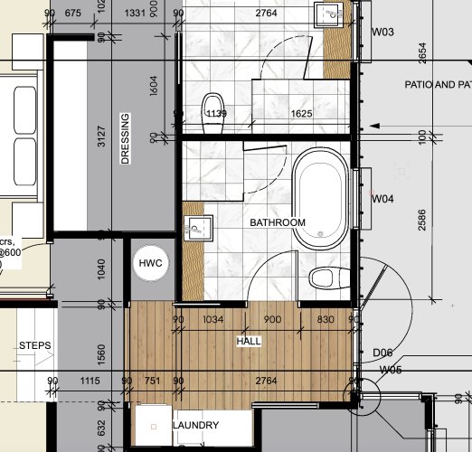
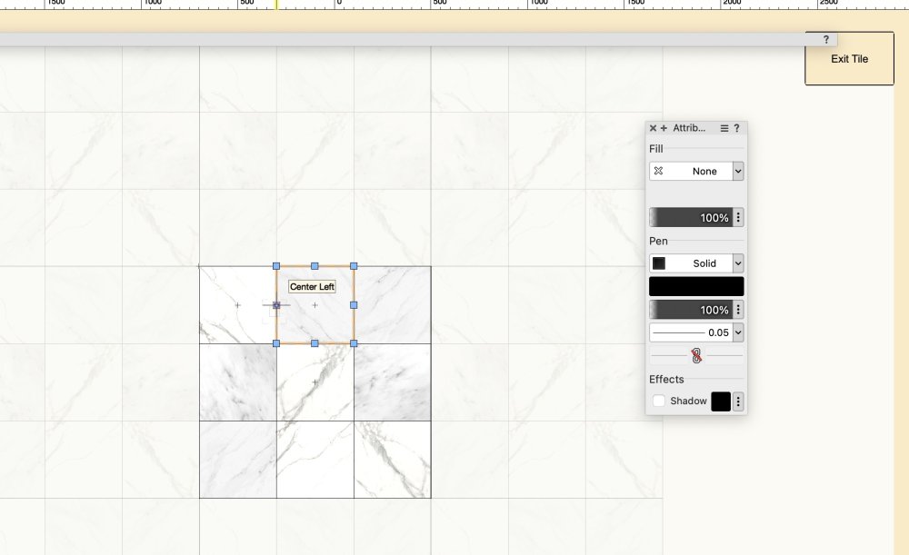
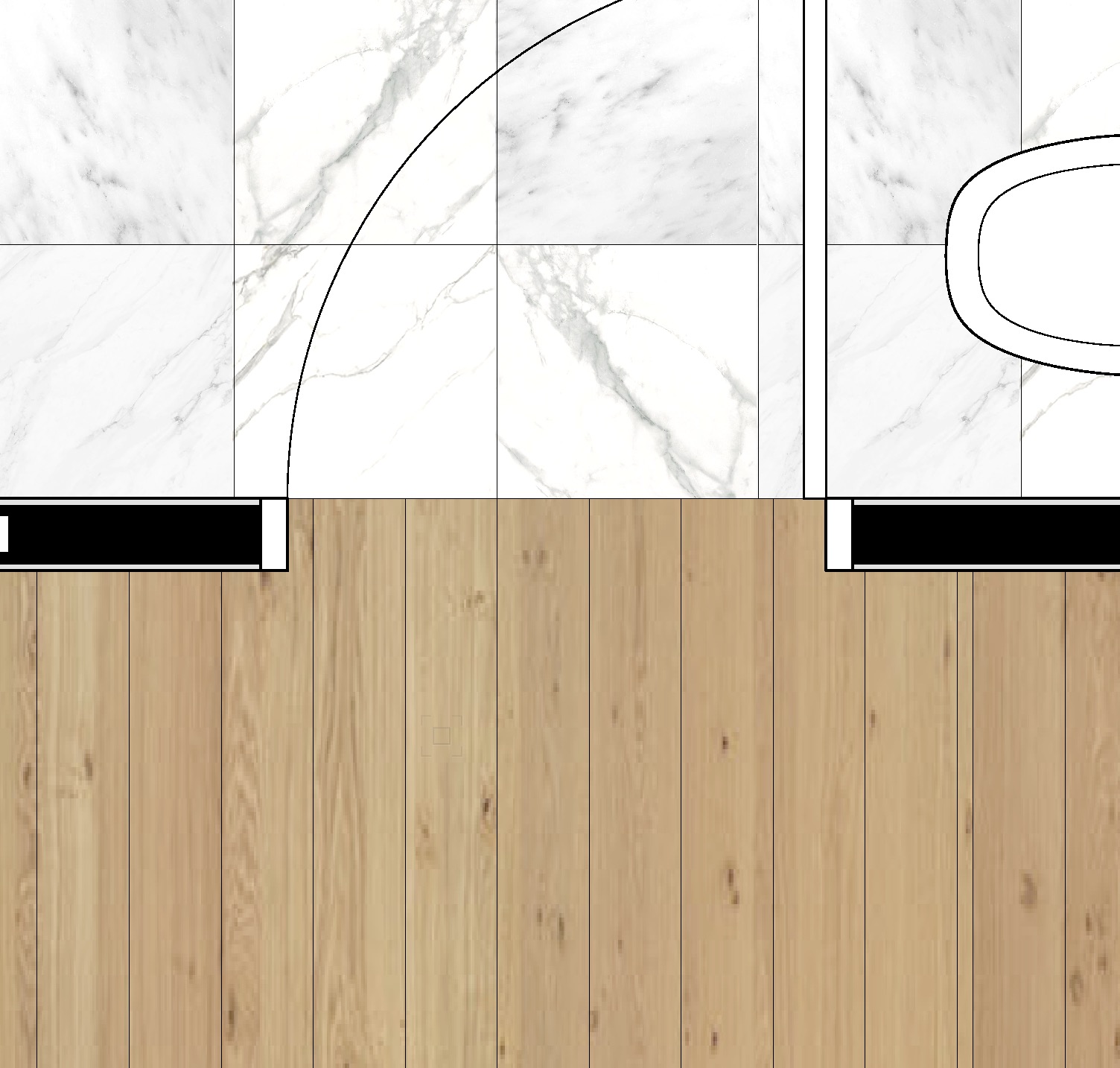
I use a "Tile" I've created in order to represent the floor covering. I draw a rectangle/polygon (on the layer plane), apply the Tile via the attributes pallet. I don't bother doing this for carpet.
It seems to be quick and easy. Also, I can use the attributes mapping tool to quickly suggest a tile layout for the builder.
Probably moving forward I should use the Floor tool, which would then show thickness in a 3d view. Draw the outline of the floor, set the fill attribute to the Tile, then AEC|Floor.
Let me know if you want instruction on building the 'tile'.
.
-
1
-
-
My setup is the same as Dave's and startup experience same as Dave's.
-
There are a number of ways;
You could draw a rectangle in this section orientation and extrude it - probably easiest method but mayn't show correctly in top/plan.
You could draw a rectangle in top/plan view, the AEC|Floor - a bit more fiddly than method 1.
You could delve into the render setting of the slab you've drawn, and change the "sides" texture to appear how you want. - this might look good in elevation but won't be noticeable in the section view.
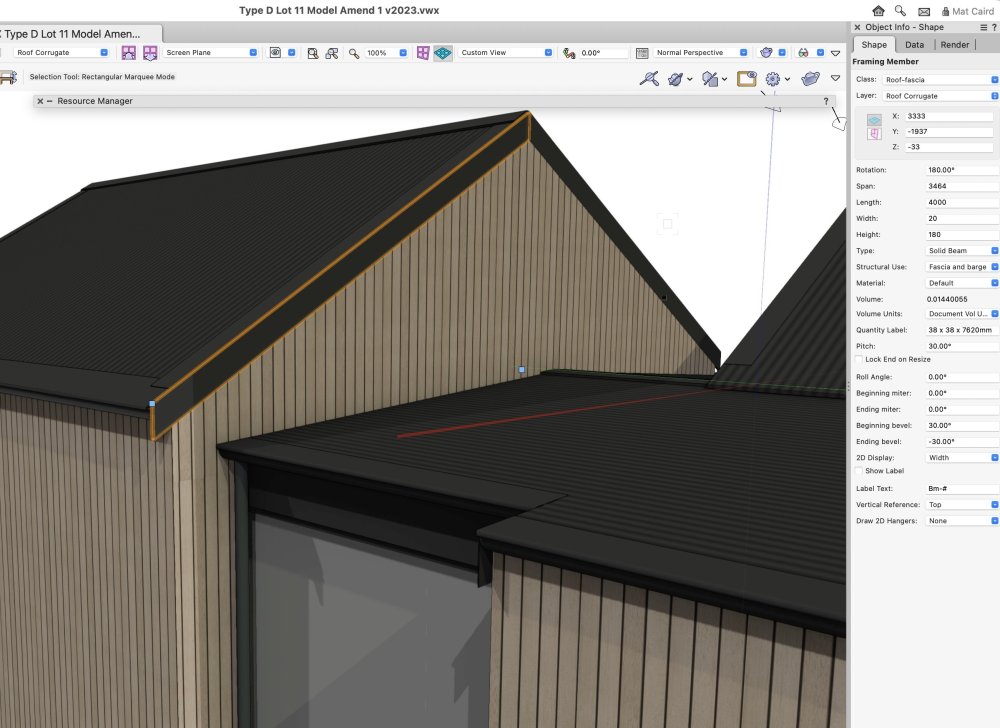
I've been using the framing member tool to draw fascias, and it works quite well.
Making a new wall style to cap it is probably the most hassle. - I'd personally avoid that approach.
Here attached an example using the framing member tool;
-
1
-
-
There is a clunky workaround; you need to size the image perfectly.
 T
T
-
2
-
-
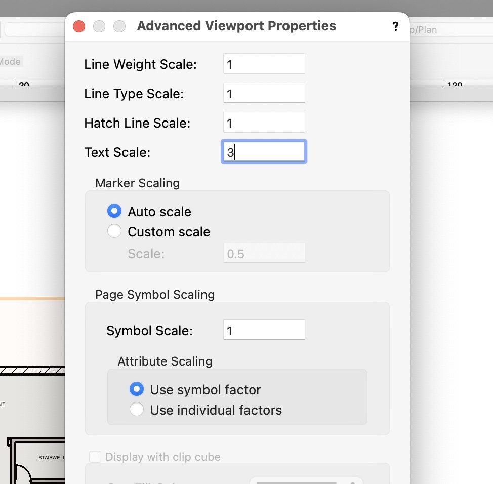
If you label the contours on your design layer, then create a sheet layer viewport at a different scale, you can use the Advanced Properties to scale the text. It won't change the viewport annotation text size, only the text on the design layer visible in said viewport..
-
1
-
-
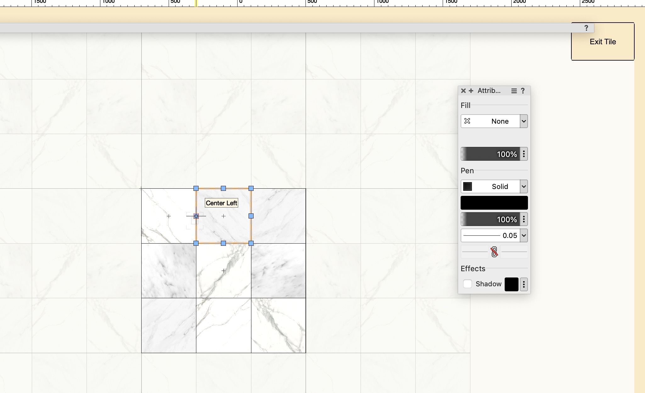
Thanks Jeff, but no. I really want to delete all the default stamps and replace them with my preferred phrases.
-
Hi All, does anyone know where I can edit the Stamp Text defaults list please? Currently I need to enter the custom text for each Titleblock, but presumably there's a text file somewhere populated with the other stamps?
OsX.
PFA.
TIA.
Mat.

-
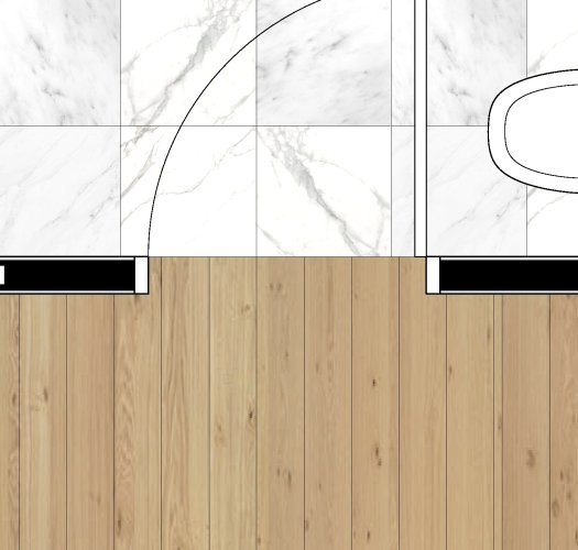
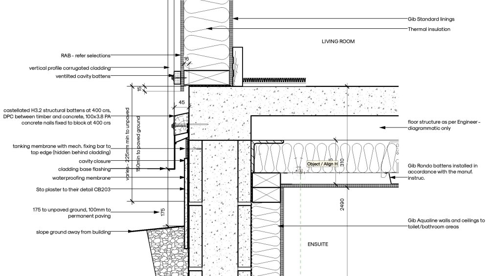
I would normally draw the wall with one or more components which actually overhang and therefore conceal the slab.
But here for you, the easiest way may be to double click the slab (in plan view), and in the Edit Slab dialog, choose Boundary, and then resize the boundary to be on the inside face of the wall.
So I would have in mind the construction method before I start modelling;
-
1
-
-
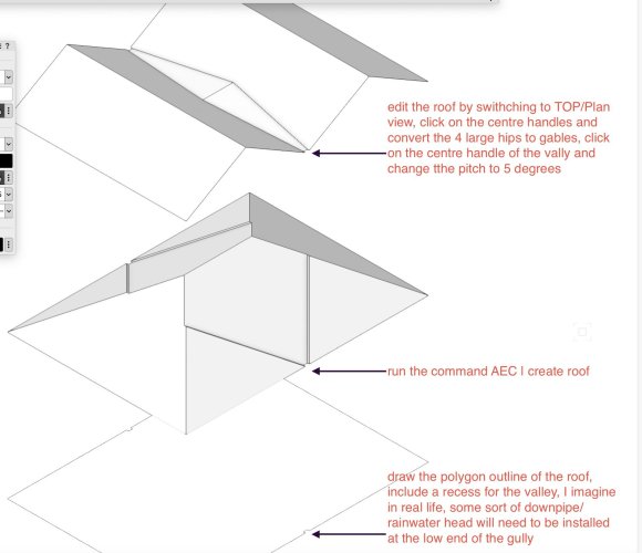
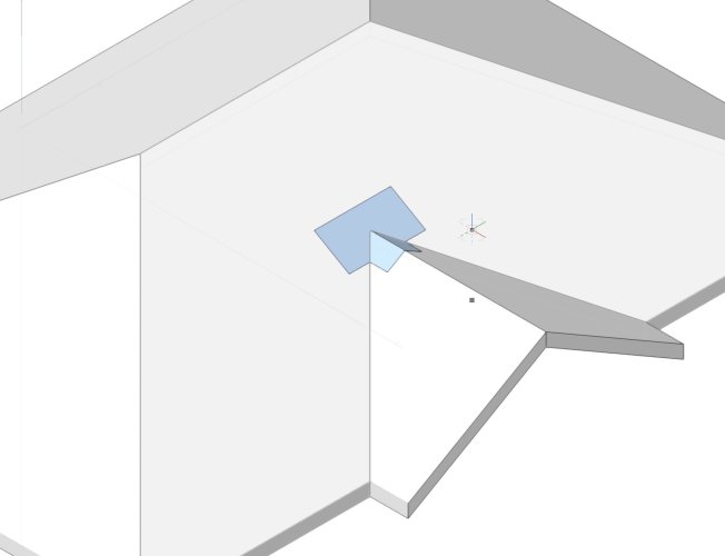
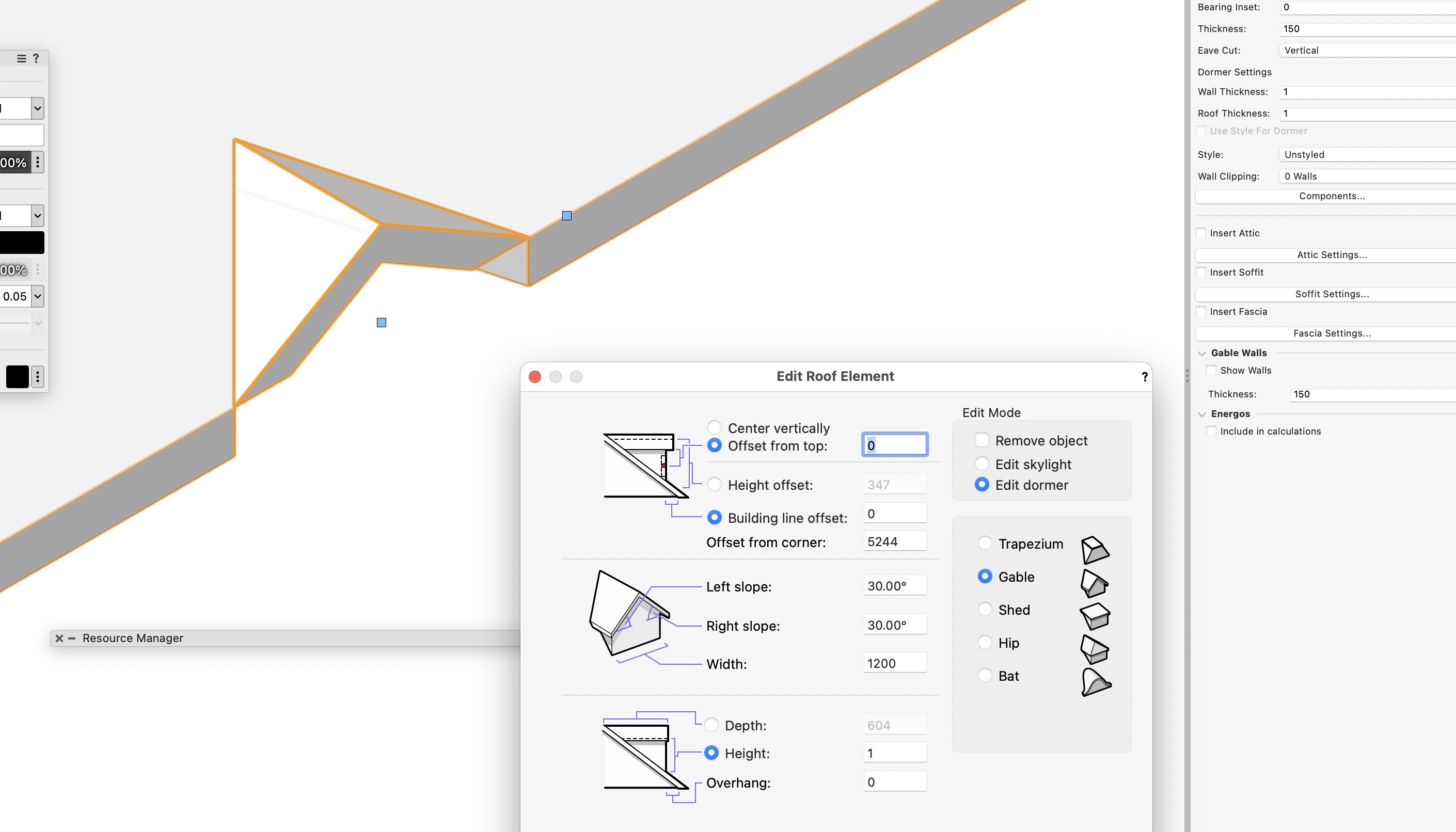
I got to here using a roof element (the roof element class is turned off in this view).

-
Or, use the create roof command;
-
4
-
-
Is this what you mean?
-
Thanks Julian for answering. I can't do them all in one hit for a couple of reasons;
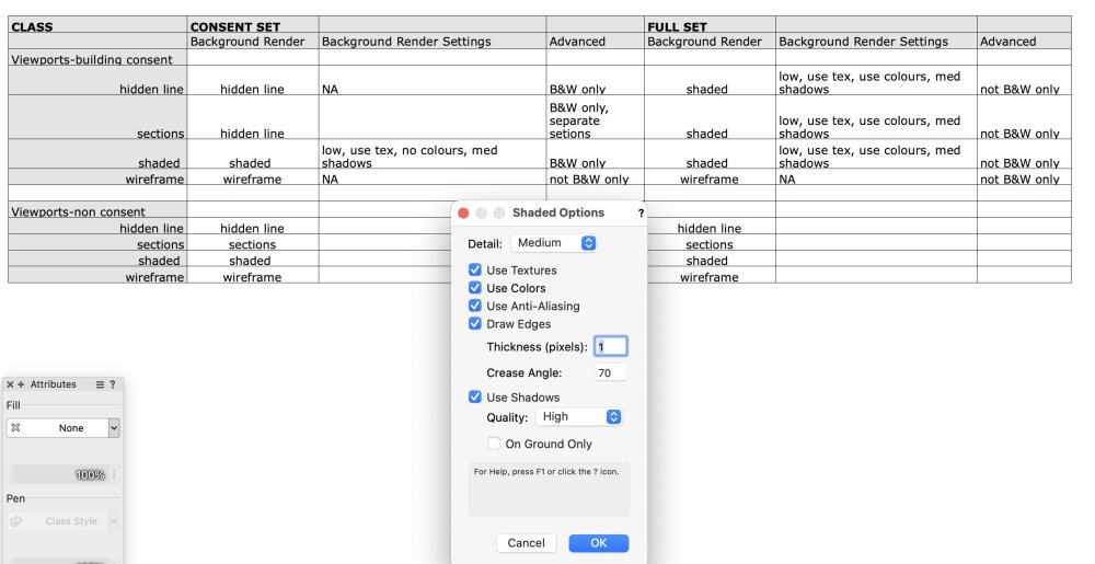
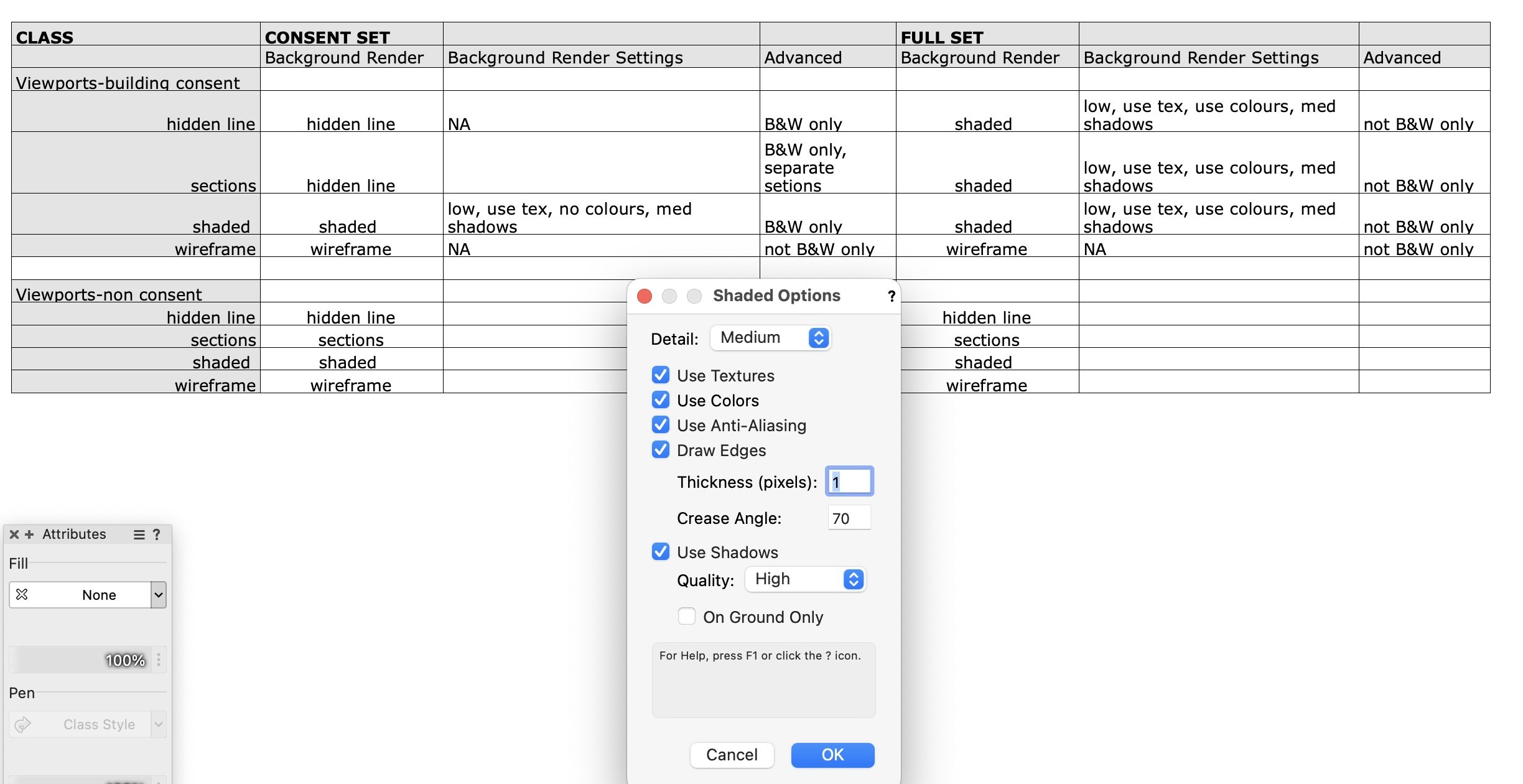
1. A section viewport and a 'normal viewport', if both are selected, and the background render mode is set to shaded, the background render settings are not available.
2. I have 11 hidden line viewports, 11 section viewports, 19 shaded VPs, 7 wireframes. For the full colour set, all except the wireframe can use the same settings so that is easy enough. But for the black and white set, the hidden line viewports I need to set differently from the shaded VP's, then there're 2 types of shaded viewport (section VP and normal VP).
If there was a VS function to select the individual background render settings for each VP, then I'd be able to write a 1-click solution to my scenario.
-
Hi All
I have a house project file with 49 Sheets. There are 119 viewports in the project, some wireframe, some shaded, some hidden line, some section viewports.
I wish to export the project to PDF for the building consent/permit as black and white, with a subset of the 49 sheets.
I wish to export a full set for the builder, in colour.
I have modelled the entire project, down to nuts and bolts, in 3d, and I'm using the viewports to produce detail drawings at 1 to 5, elevations at 1 to 50 etc.
I have placed the viewports onto classes describing their Background Rendering setting. eg "Viewports-building consent hidden line"
I have used the Tools|Custom Modification tool to create a script to select viewports of the same Background Render. Then I manually adjust the render settings.
EditProperties(((T=VIEWPORT) & (C='Viewports-building consent wireframe')));
I've looked at the Vectorscript Function Reference but cannot find any function to "deselect 'use textures shaded render'". Is it possible to edit the background render settings using VS?
Thanks in advance. Apologies for the I have I have I wish I wish.......
Mat
-
Hi Jim
Try this;
edit the class named Note-Redlines to <use at creation>
in that class, tick use at creation in the Text Style box of the same class dialog then select your text style "Callouts 10 Pt"
click OK - it might work, if not;
find the attributes pallet, and left click on the 3 lines, beside the ? - choose "make all attributes by class"
-it might work, if not;
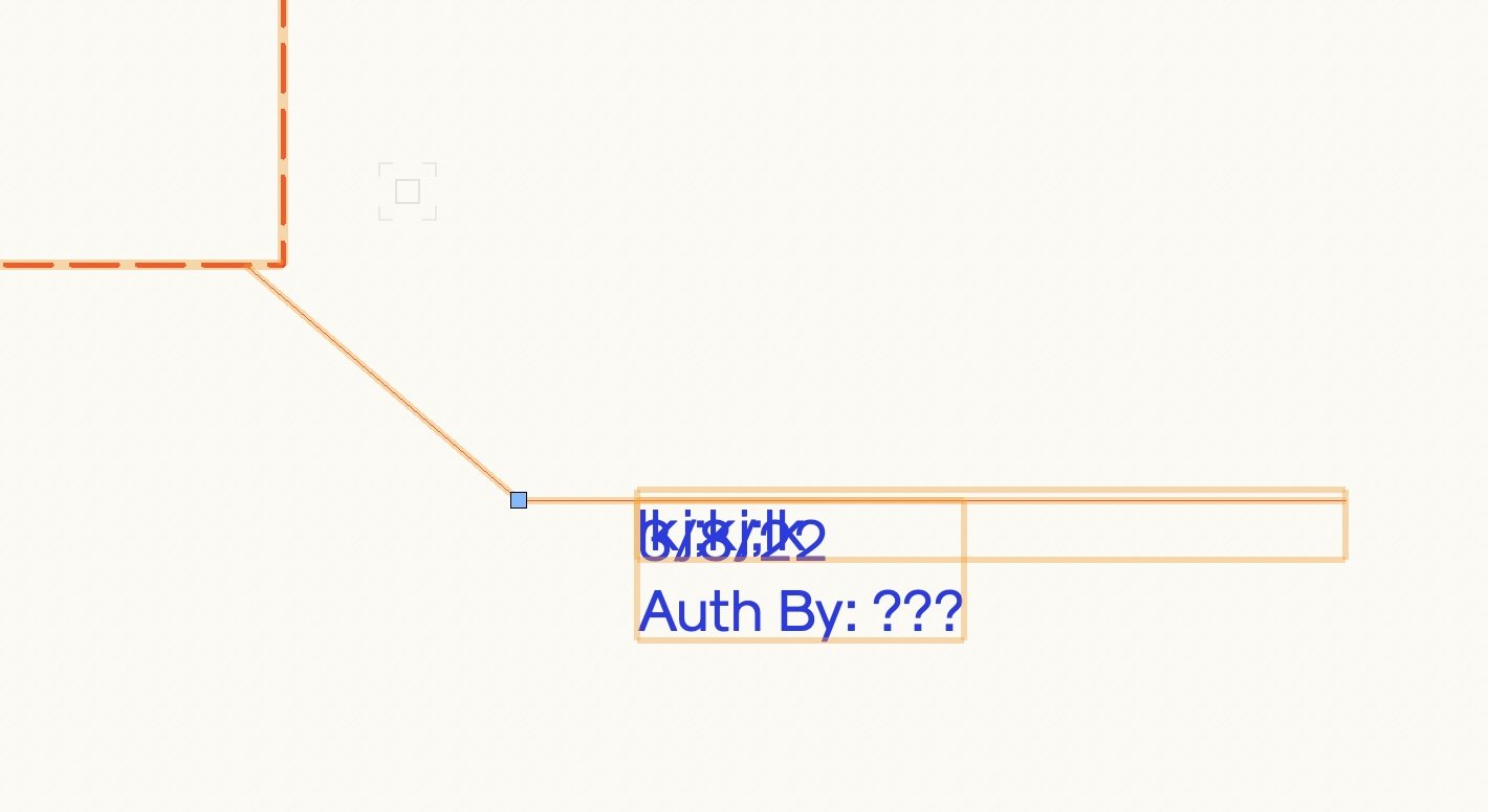
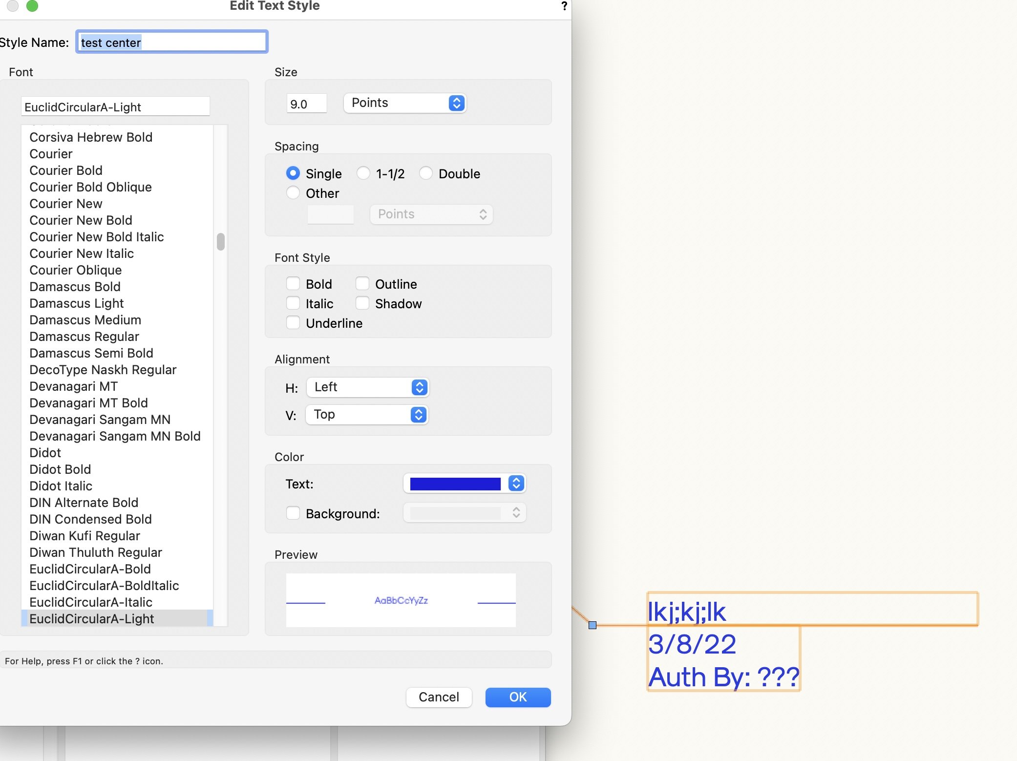
right click on the redline and choose "locate text style in resource manager", then right click on the text style, make sure the alignment is not set to top baseline, or bottom baseline. Change the colour of the text just so you can see if the redline is actually updating. Click OK. You'll probably need to "make all attributes by class" again.
Finally, you might need to flip horizontally, or flip vertically your redline object.
Good luck - it worked for me.


-
Here’s an idea;
make a new layer, call it "curtain wall". Draw the curtain wall on this layer
Make another new layer, called "floor plan 1" draw the program
same for another new layer, floor plan 2. Etc
Make sure all 3 layers are the same scale.
use the layer options "show snap modify others"
turn on/off layers 2 and 3 as necessary
an alternative; if the curtain wall is aligned perfectly (as it would be IRL) across both floors, and drawn on both floors (layers), VW will display it as one wall in elevation, 3d, section views. Provided the wall style is the same on both layers.
Mat


Renderworks Background using BOTH photo AND PANO images - how to edit & fine tune these
in Troubleshooting
Posted
I don't think you can move the renderworks background. You can edit some aspects of the background using the resource browser. But not the position. I think it just fills the *screen*
A friend of mine makes a giant cylinder, say 400m diameter, 100m tall, and applies a panoramic image to the inside face of the cylinder (he does this by making the image a render works texture in the normal manner). You can then control the texture in the normal manner. I haven't tried this method. I'd be interested to see if it works for you.