
Jeff Prince
-
Posts
2,919 -
Joined
Content Type
Profiles
Forums
Events
Articles
Marionette
Store
Everything posted by Jeff Prince
-
I just read your message. Unfortunately, there was no lidar, .vwx file, or project coordinates attached or in the link provided, so I'm unable to review the site. I did look at the lidar available in what I suspect is your vicinity of interests. It looks like the 2019 data is most comprehensive. I was able to pull that down and generate a site model of a fairly large area using 4 different point clouds. This is good because it tells you the data is there and it's possible to do something with it. Here's some of the vicinity brought into Vectorworks. So, 1st you import the point cloud. It seems the data either lacks geographic location or Vectorworks is not importing it correctly. This is where those .shp files of the LiDAR study area are handy, as those do come into their real world position correctly, so import those first. Then, you can move the point cloud(s) in Top/Plan view to line up with the geometry of .shp files and/or the GIS aerial image built into Vectorworks. Using top/plan for this move prevents you from snapping to an incorrect elevation and preserving the elevation in the LiDAR. Once you have the LiDAR situated correctly, you can convert it to a site model by selecting it and then issuing the "create site model from data" tool. You can choose the number of points to import, which is essentially decimates the point cloud for you and takes out a large number of those trees sticking up in the air. Finally, edit this site model by "recreate from source data". This will give you access to the points. Using the clip cube to work small sections at a time, you can delete points that you do not wish to use. After you are done, the site model will be rebuilt. Repeat the process as required and your model will take on a smoother appearance. In terms of using Blender with geographic point clouds, there is a lot of information on the blender sites and YouTube about Blender GIS and LiDAR Decimation if you want to learn more. Just be warned, this requires installing add-ons and a higher comfort level with Blender. Hopefully @Katarina Ollikainen or @Tom W. can help you out, I'm going on break for a bit 🙂
-
Turn your joint in a symbol. This will give you greater control over graphics and orientation. Plus, when things go wrong, you only have one thing to fix instead 100s 🙂 I draw two crossing lines at 90 degrees. I then color one red and the other green (like the axis) and turn it into a symbol. This gives you visual orientation of the rotation and makes it easier to adjust. See attached file for example. The original joint I created did not rotate correctly so I drew some helper lines and dimensions to determine how the symbol geometry needed needed to be rotated. I left that stuff in there so you can see how it was prior to repair. Using the Red, Green, Blue convention for axis depiction can really help you see what is going on with the tools as you use them and provide insights into how to fix things. Now, you might be wondering "why does Vectorworks place my line in a seemingly random way". It looks that way, but isn't random. Everything is related to the start point of the path. If you draw your joint at the start point of the polyline and in the proper orientation, things will work as they should. It's just we generally don't think like that when designing. So, in your example, the "correct" drawing of the joint would look like the line in green below. It is drawn from the start point of your path to the perpendicular offset path, kind of like your line drawn in red, but orientated about the start point of the path. The cumulative worldwide wasted energy on topics like this due to Vectorworks logic could power a small village in perpetuity 🙂. You would think that selecting the 'center, tangent, keep orientation' options (which you need to activate in this example) would help VWX figure this out, but no, you still have to draw the geometry correctly. DUPE ALONG PATH-symbol trick.vwx

-
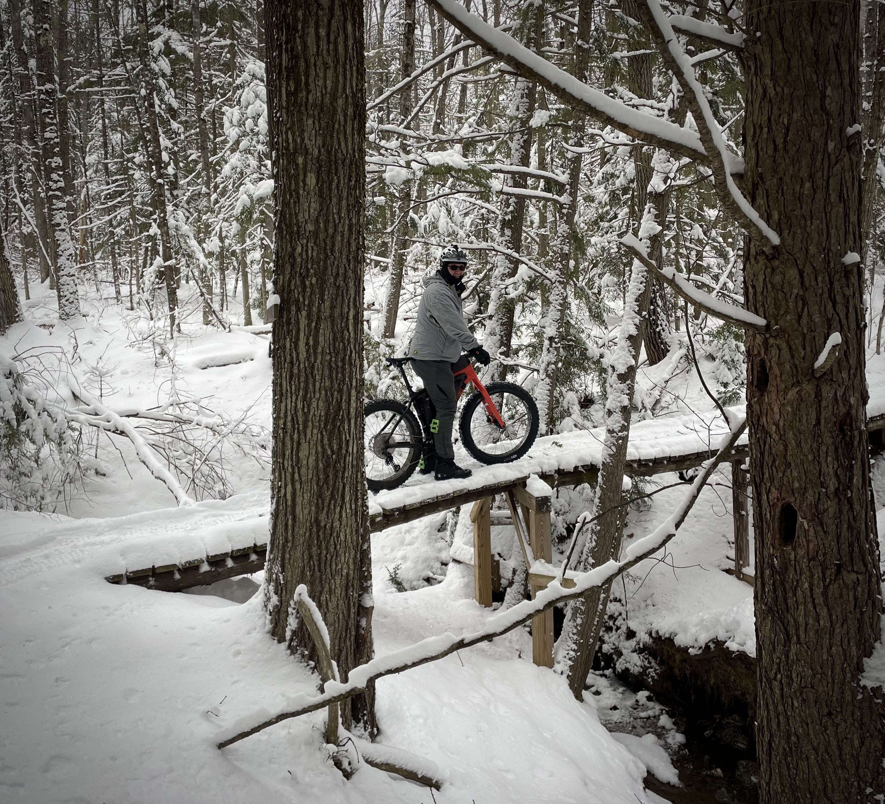
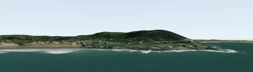
I received your message, but the data was not point cloud data, it was GIS data depicting the area your are interested in, boundaries and descriptors for aerial surveying done to collect lidar, and a geoTIFF DEM. DEMs are raster heightfield information where the greyscale value of a pixel in the image determines elevation. Vectorworks does not have a method of using that type of data. Blender and Rhino do, but you would be better served collecting the actual point cloud files, typical .las, .laz, or .pts. These point cloud files describe geolocated points in 3D space, which Vectorworks does understand. Here's an example of what you can do with raster data in appropriate software: Landscape Visualizations
-

Screen recording Vectorworks
Jeff Prince replied to Cadplan Architecture's topic in General Discussion
@Cadplan Architecture I should get a commission for selling the built in Quicktime screen recording 🙂 I just recorded this using the techniques described earlier. I was using my AirPods. You don't even have to go into iMovie to trim the clip or reduce the file size, these are features built into Quicktime. The best part of using this technique of saved views is you can easily go back to a view when someone asks a question. I had to do this a lot during the Covid days of Teams/Zoom presentations. Saved views made things easy. It's slicker when you have two screens and can do your Vectorworks controls from the second screen and just present a clean view of the model with no distractions. Bonus: you don't have to "educate" Revit people on what software you are using. screenrecordorbit.mov -
Screen recording Vectorworks
Jeff Prince replied to Cadplan Architecture's topic in General Discussion
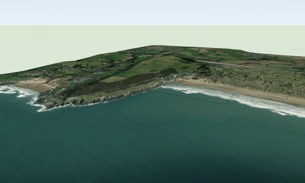
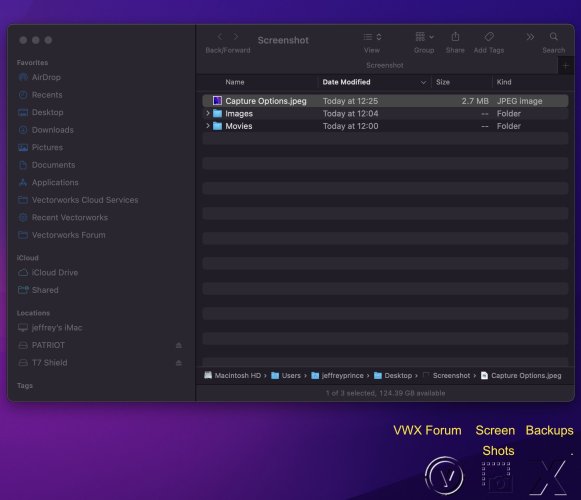
I know you said you have tried to use Quicktime, but it's really easy once you get the hang of it. I encourage you to give it another shot before buying something if you only need basic recording of screen and/or audio. The fastest way to initiate the screen recording and options is Command + Shift + 5. You can also access it by opening Quicktime Player, File \ New Screen Recording. Hit the options button and configure to suit, here's how I use it: Save to: I save all my screenshots and screen recordings to a folder on the desktop specifically for that purpose. You can do the same by hitting the "other location" menu option and choosing a place to save. I made some unobtrusive transparent icons for commonly used temporary folders and stuck them in the lower right of my screen. The yellow text was added for the purpose of this illustration, normally you just see the icons. Timer: I just started using the 10 second option. This is a handy way to get yourself ready for audio recording. Hit record, take a deep breath and Go! Microphone: Set it to none, or if you want to record audio of your screen recording, pick the appropriate attached microphone. AirPods or a dedicated mic work much better than built in. Options: Show Floating Thumbnail just refers to when you are done recording or taking a screen shot... a little thumbnail briefly appears in the lower right of the screen. I like it because it gives me confirmation that I took the screen shot when I'm doing a bunch of them. No need to go check the folder thanks to the thumbnail. Remember Last Selection should be self explanatory. Show Mouse Clicks is pretty handy when you are trying to demonstrate how to do something on screen, not so useful when rotating a model 🙂 Actually that is incorrect, see above.
-
Let me know if you need someone to write the foreword for your manual 🙂
-
If you send me links to the specific datasets you want to use, I can tell you how to manipulate them in the next day or so. It's possible some of the .shp files you downloaded are only polygons representing the rectangular tiles to be downloaded, not very useful for your purposes, but typical with government data to delineate collection areas or tiles completed... not the actual data 🙂 Anyhow, if you make life easy on me for looking at the specific data sets you want to use and project limits, I can give you some pointers. About the images you posted. The point cloud that has houses and vegetation in it needs to be edited if a ground surface only version of the file is not available as @Amanda McDermott was suggesting. The easy way to do this is with Agisoft Metashape with offers tools to expedite this kind of thing, especially if the vegetation and structures can be classified and filtered. However, you can manually delete points from the cloud in Vectorworks. Using the clip cube to isolate areas for editing and having a copy of the incorrect site mode in the background can make this much easier, but It's a laborious task if you are doing large areas.
-
You guys are flirting with the answer and in the right neighborhood. No need to rebuild the site model. Rare problem, but easy to fix. Essentially, your modifier does not have enough points along its perimeter for Vectorworks to triangulate the surface to your liking. The fix is to add vertices to the modifier along its perimeter. When you see weird triangulation like this: It's a harbinger of doom when it comes to site models and usually means you need to add some vertices to assist the triangulator and/or revisit your site model and hunt for overlapping vertices on 3D polys.

-
My pleasure. As you are probably aware, a point cloud is a bunch of 3D points defining a surface. LiDAR at 1M resolution typically has one point per square meter. So, for a small site, that isn't too much data, but for a 10km x 10km area, it could be exceptionally point dense and bring your computer to its knees. That is where decimation can be handy during import. You'll see the total number or points and can reduce it to an acceptable %, based on your computer's horsepower and experience. I usually try 5% to see how quick a new data source will come in and increase the % on subsequent imports as I see how fast it it. I recommend not having any files open when bringing in a point cloud for the first time. Once you know it will behave nicely, you can then reference it into your working file or directly place it. Just make sure you back up all your work before importing point clouds, you can sometimes run into problems with them that can cause a loss of work. Tutorials... I can't remember if there are any on Vectorworks University or not, but that is the place to look. I've posted a lot of information about site modeling here on the forum which you can find by searching my name as author. Hopefully some others will jump in here, I'm taking a break from the forum for a while, hence the "adios amigos". I will still be doing paid tutoring during my break and can be reached by private message here.
-
@DaveNorton I have an explanation and solution for this, but I would like to see if one of the experts here or from Vectorworks can get you sorted before I share it. @Tom W. @Katarina Ollikainen
-
It depends on the resolution and timeliness of the data. It seems that "National LiDAR Program Point Cloud" at 1M resolution might be okay, depending on what you are doing and how accurate it needs to be. You would then import that as a point cloud if it's in .laz, .pts, or similar point based formats you can see in the import point cloud command. Keep in mind, government sourced LiDAR and GIS are generally far from "survey grade" data, meaning they are okay for starting a project, but if you need high accuracy... you will eventually need to get a proper survey done. Then, request a point file in .CSV format from your surveyor to get the best data into Vectorworks. Hopefully one of your UK colleagues like @Tom W.. Nope, you have to import it in a suitable format and build a site model with said data.
-
Site Model not affected by Site Modifiers Vectorworks 2023
Jeff Prince replied to TeeMuki's topic in Site Design
I don't think it work like that anymore and hasn't for a long time apparently... There are work arounds, depending on what and how you want to show it. -
I find shapes like this are easiest to make with a Loft using 2 profile curves in Vectorworks.
-
Just for fun. Note how the fabric hangs inside and outside the diameter of the table, creating an interesting shadow 🙂
-
Here's how people on the forum can help you troubleshoot it further.... 1. Copy and paste the problematic wall into a new file. 2. See if the behavior continues. 3, If so, save the copy and post it here so we can have a look. This will keep the file small and prevent you from having to share your entire model.
-
I responded to your other post on the same topic with a video. @Matt Panzer is right, more info is needed to understand why your situation is behaving differently.
-
Are you trying to do something like my attached video? If so, how is the process different on your end? sloping curved wall.mov
-
My pleasure, that’s great to hear! Now, make sure you keep it running well by observing the maintenance schedule and keeping it clean. Build up of paper dust, ink vapors, and mangled bits of paper stuck in the throat are usual the cause of most issues.
-
Switching from PC to Mac Ecosystem - any regrets?
Jeff Prince replied to StagehandPv's topic in Hardware
I spent over 20 years on a PC for my professional work. No regrets (or blue screens of death) since moving to Mac. I used an iPad extensively prior to making the switch. Life is much easier now as I can move seamlessly between the desktop and iPad for much of my needs. I also replaced Adobe with Affinity, so there is a huge advantage there using a Mac/IPad compared to the PC/IPad situation. Overall I feel the switch has led to fewer issues, greater productivity, and more joy in the design process. All that equates to higher profits too. I will occasionally get a pinwheel of doom while using vectorworks, but that is something to do with asking vectorworks to do something complex that fails on the PC too, so more of a VWX issue than Mac/PC. If you do the switch, read up on how best to use ICloud for all of your devices and relevant workflows. This is really the key to getting the most out of the system. -
site model question (stairs/ramps next to retaining walls)
Jeff Prince replied to DDD's topic in Site Design
Happy to help. FYI - I typically just do a single retaining modifier to carve out the whole area for a stair set and cheek walks on small landscape sets like these. It makes it faster to edit the modifier if your stair pitch or position needs to change 🙂 -
I think you hit the nail on the head. I see architects constantly improving their landscape renderings without really know much about landscape plants. They can easily paint a random collection of plants, shrubs, and even weeds and grasses using a 3D brush you simply drag across the screen for most of the temperate world. I used to tell architects that buildings are easy, landscape visualizations are where the challenge is... but that is changing rapidly. Bringing it back to where this all stated... Blender is evolving so rapidly and in so many directions, it sure would be nice for a clean workflow between VWX and Blender (& Rhino). There are things you can do in those packages to enhance the work made in Vectorworks, but will never be developed for Vectorworks. Like who is ever going to create a procedural alleyway generator for Vectorworks? Someone did for Blender, and that is a niche within a niche. The amount of more universally useful stuff out there is mind boggling. The Rhino / Grasshopper community is generating tons of useful stuff too. Random terrain generators, terrain from DEMs/raster images, excellent slope analysis, solar analysis, etc, etc, etc... I was farting around with Rhino earlier this year after a very long hiatus. I'll probably have to get on board with it rapidly if I'm selected for a certain project in the the Middle East, as it is the primary conceptual design tool shared amongst the 12 studios involved 🙂 Just more reasons to connect Vectorworks to the larger ecosystem...
-
@zoomer doesn't it seem Vectorworks w/C4D is the one at a disadvantage here with regards to being connected to a greater ecosystem of modeling and rendering? Modelers like Blender, Sketchup, and Rhino have many rendering engines they support and integrate with. Where those of us who model in Vectorworks have fewer choices and more difficult workflows when we are required by client/collaborators to move our work into other software environments. Exports like: Vectorworks to Sketchup? Vectorworks to ArchiCAD? far from seamless. Lots of export formats kick out 3D only, leaving textures behind. That's kinda painful. It's still not flawless moving from Vectorworks into Twinmotion, which has sync and support from both vendors, yet fails on many fronts. It's getting better, but still... I can see why several of my Vectorworks architects still use Sketchup for their conceptual work.
-
Hardscape material 2D and 3D settings
Jeff Prince replied to Devonshire's topic in General Discussion
You are hitting a bunch of topics all at once. You should probably try the Materials workflow if you want your 2D and 3D to match all the time. Using the Hardscape tool's Joint feature with Textures doesn't work the way you would like to. -
Hardscape material 2D and 3D settings
Jeff Prince replied to Devonshire's topic in General Discussion
No, you have to do that manually. The 2D and 3D need to behave separately... 2D needs are driven by plans at various scales while 3D needs are typically driven by rendering or diagrams. -
Vectorworks Save reminder alert
Jeff Prince replied to Cadplan Architecture's question in Wishlist - Feature and Content Requests
You will likely reconsider this the first time you accidentally turn off Autosaving. People usually don’t notice this happened until disaster strikes. The reminder creates some piece of mind that your backup will probably be there when you need it.