


Ryan Seybert
-
Posts
118 -
Joined
-
Last visited
Content Type
Profiles
Forums
Events
Articles
Marionette
Store
Posts posted by Ryan Seybert
-
-
@Nikolay Zhelyazkov You are correct, the titleblocks were built without borders as the company is very specific about the look of them. This also, prevents us from changing the scale factor to make them fit.
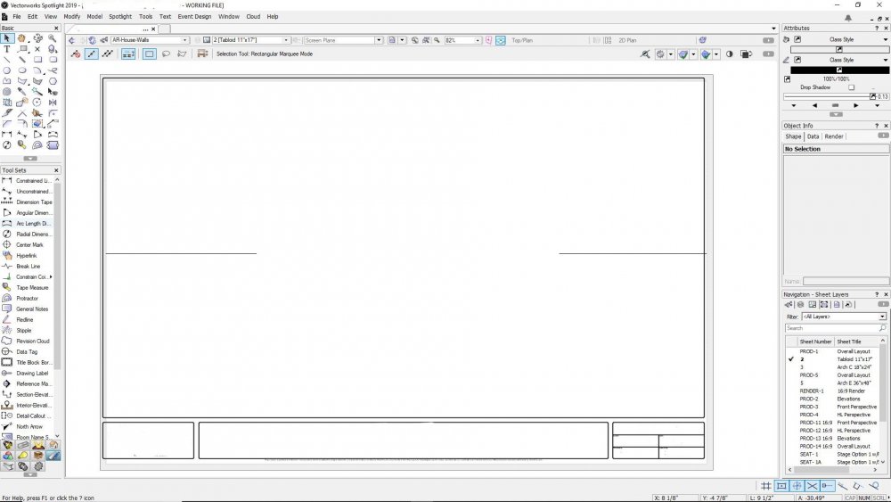
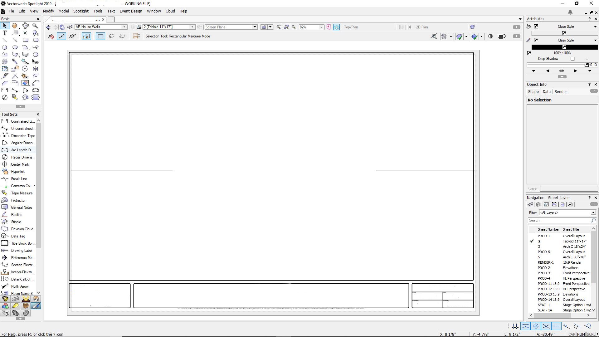
I've attached a screen shot of a sheet layer illustrating the issue. I've erased the confidential info so there are some spots that will look incorrect. You can clearly see that the titleblock is outside of the "print boundary". This is exactly how it was when I opened the file.
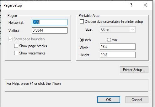
I've also attached a screenshot of the page set up window showing that "choose size unavailable in printer setup" is deselected. If I check that and select "One Printer Page" the titleblock will align to the page correctly. This adjustment will last until another users logs into the file and has to make the change again. Changing the "Pages Horizontal/Vertical" page size to 1/1 will yield the same results.
One thing to note, is that 90% of the collaborative work is done with project sharing, however, even when a file is not a project file the issue is still prevalent. The only time we don't have the issue is when the file is only ever opened by one person, usually a person detail drawing that only that user will draw in.
-
@Nikolay Zhelyazkov Thanks for the reply.
I've attached a chopped up version of our start template as a test file for you. Hopefully the issues is still intact after purging out all the other proprietary info.
There are two sheet layers, Letter and Tabloid. Those two are the most used out of our title blocks. All of the ARCH series don't seem to give us too much trouble.
Please review and let me know what the issue is. Its likely an error on my part when I built them. We recently transitioned over from AutoCAD where building title blocks was as simple as drawing the line work, adding some data attributes, and making a symbol out of it. The VW title block process seems to be a bit more tasking.
Thanks again for the help.
-
HI All,
We have recently switched over from AutoCAD and are having some difficulty with printing sheet layers. In AutoCAD, when you crate a title block symbol, you draw the exact sheet size as an outline and draw the title block line work accordingly and taking general margin dimensions into consideration. Never really had a problem with it.
Vectorworks seems to be a can of worms. The challenge is that whenever another user tries to print a layout they must first adjust the page settings for that sheet layer.
The steps we have been doing are the following:
- Edit Sheet layer by double clicking on the target sheet layer.
- Click "Page Setup".
- Select "Choose size unavailable in printer setup".
- In the drop down, select "One Printer Page".
- Hit "OK" three times to exit out of the Sheet Layer Manager.
If we do not follow these steps we end up with the Title Block sticking outside of the page print boundaries. How do we set this up so we do not have to do this every time?
Thanks!
-
Whats the fix for this?!
Thanks in advance.

-
Hi all,
How do you set a symbol to take on the attributes of the class its placed on?
In AutoCAD, you build your block(symbol) on the "0" layer. Once created, all objects within the block definition that don't have attributes assigned to them take on the attributes of the layer(class) the block(symbol) is currently on.
We've just made the switch to VW from AutoCAD. So far we're very impressed with the software but we're struggling with some of the differences.
Any help would be greatly appreciated.
Thanks!
-
 1
1
-
-
Hi all,
I would like to export a drawing to PDF but without line weights. We often send out drawings of very large productions in a very small scale via PDF. The line weights have always be an issue with this. Coming from an AutoCAD background, before plotting you can check/uncheck "plot with line weights". Is there something similar with Vectorworks?
Thanks in advance.
-
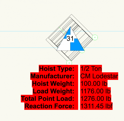
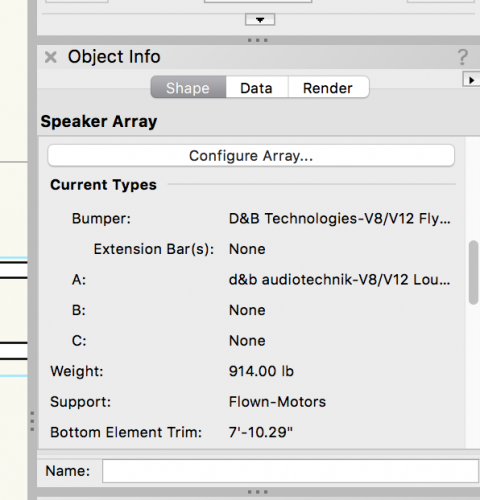
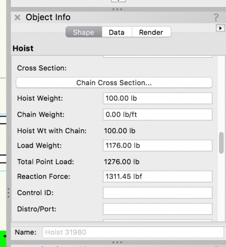
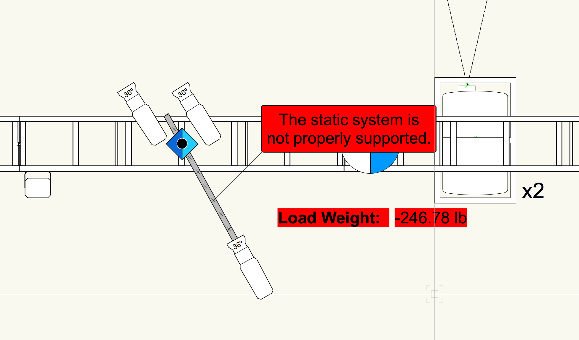
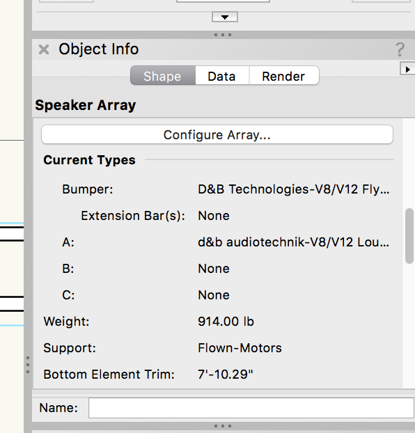
I have a motor point picking an audio array and the load weight is off by 262lbs.
1/2 Ton motor = 100lbs.
Audio Array = 914lbs.
Total Point Load = 1,014lbs.
Braceworks is calculating a load of 1,176lbs. with an excess of 262lbs., roughly 28.67% of the load. Not sure where its coming from.
It also seems to scale larger when the load becomes larger. I changed the array so that it was a flat 1,000lbs. The excess grew to 350lbs., 35% of the load.
I've attached some screenshots for clarity.
Any help would be greatly appriciated.
-
The trick seems to be move the Array to the motor point or the truss. The motor point or the truss will do its little red thing and then it'll connect.
-
3
-
-
-
Anny chance you can provide a step by step on how to accomplish the 1/101 display? Been racking my brain and its getting pretty frustrating.
Thanks in advance.
-
Would love to see the ability to link truss to the sides of another truss on the same plane. this would be accomplished by a grapple or other type of real world hardware. This is not a major issue with Spotlight as it is once you run calcs in Braceworks. Braceworks will see this as an unsupported connection.
-
1
-
-
Hey all,
Thanks for the replies. I've attached a few screen shots to better illustrate what we are trying to accomplish.
1- Are the VW plug-in objects you speak of built into VW or are they third-party add-ons?
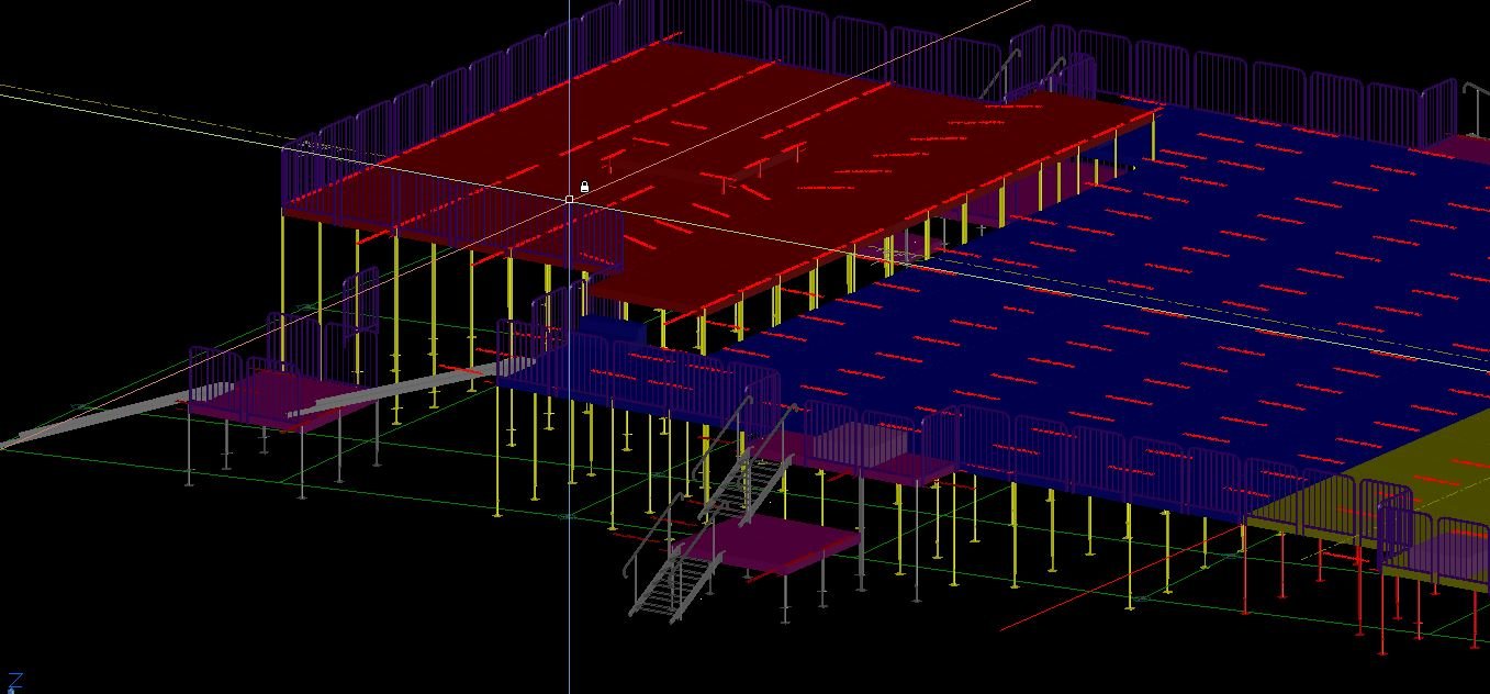
2- I'm somewhat familiar with the built in staging tools. What I'm interested is when we build a deck on an unlevel surface, being able to drop in the parts we need and be able to retrieve the parts list from the program through some means of data export. I've attached a screen shot of a large deck we built for a private function. The deck was built on a field that had a dramatic downward slope. When we detailed the deck out, we essentially placed each leg (the deck leg tool) and then manipulated the "block/symbol" via the visibility parameters that I built into the tool. If something like this currently exists with-in VW or a third party add-on I would most definitely be interested in checking it out. Its one of the major things that my scenic department is adamant on having before making the switch to VW.


-
Thanks for the reply. I figured this was the best way to accomplish what I'm trying to do outside of the workgroup option.
-
Hi Pat,
Thanks for the reply. I spoke with Andy briefly on another unrelated thread.
Looking forward to their responses.
I can post some screen shots of the tools when I get to my office.
Thanks.
-
Do you really need to have the Design suite in order to share workgroup resources from a cloud based collaboration service such as Dropbox?
-
Hello All,
I work for an event production team that is looking at making the switch to Vectorworks Spotlight from AutoCAD. We're all pretty proficient with AutoCAD, some more than others. We are looking at making the switch as AutoCAD does not support out industry specific demands.
We have a couple dynamic blocks that I built for use in AutoCAD that are really important to our workflow. Any help as to how to recreate them in Vectorworks would be greatly appreciated as they weigh in greatly on our disicion to migrate to Vectorworks or not. See below.
Triangulation block:
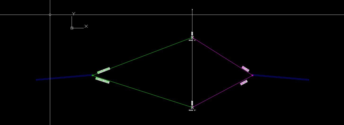
When we are on site, we utilize triangulation to mark out where we place our structures and production elements.
Currently, the process consists of three elements:
- Point "A" - simple block with a polar stretch feature that allows us to stretch a line segment along a fixed angle to a designated piece of architecture. The length the line is displayed on the block and is also exported for use in a spreadsheet as well as printed on stickers.
- Point "B" - Exact copy of Point "A" except it is redefined as Point "B" for data export purposes. Commonly, it is placed 20'-0" from Point "A".
- Spike Point - This is the real work horse. The insertion point is meant to be placed on the point you wish to triangulate. The block contains two line segments, both with non-polar stretch functions. One line is stretched to Point "A" while the other is stretched to Point "B". Each line segment displays its length as well as exports its length for use in a spreadsheet as well as printed on stickers.
Block with Visibilities:
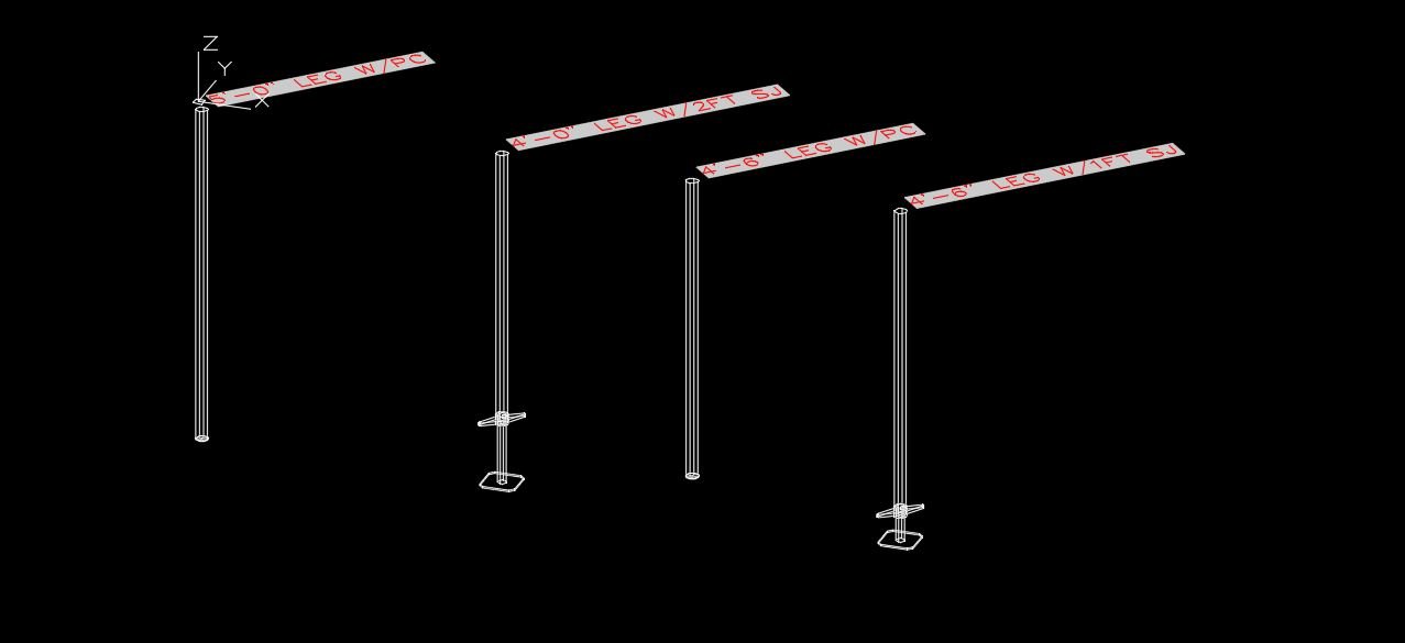
We have several blocks in our arsenal that deploy visibility states for quick drafting as well as exporting data about that particular objects. One in particular, is a block that contains about 32 different iterations of a stage deck leg, with each iteration being a selectable visibility.
Each iteration is comprised of two separate blocks: the leg and the foot. Some examples are:
- 12" leg w/plastic cap
- 30" leg w/screw foot
- 60" leg w/screw jack
When that block is exported, we have a spreadsheet that tells us how many of what are in the drawing, allowing us to order the correct number of parts.
Any help on how to replicate the above described would be greatly appreciated!
-
I wouldn't mind seeing the fixture take on the attribute of what cable its receiving. For instance, if you run 10ft L6-20 and 25ft 5PIN jumpers to a fixture it would populate user fields for use downstream in paperwork and lighting tapes.
Unless there is a way of doing this already... I'm coming from about 12 years of AutoCAD. All my symbols have cable fields for use in paperwork and truss tape. Rather surprised VW doesn't have these fields implemented already.
-
1
-


Lighting Symbol w/Assigned Class?
in Entertainment
Posted
Hi All,
My entire Lighting symbol library has classes assigned to each class so that when they are inserted into a new drawing they are automatically on the class I want them to live on. The issue is that although all the symbols are "assigned" to a specific class, they do not actually come in on that class. Instead they come in on the active class.
What am I missing? I'm still relatively new to VW so I'm sure I'm missing a step.
Thanks in advance.