Claes Lundstrom
-
Posts
227 -
Joined
-
Last visited
Content Type
Profiles
Forums
Events
Articles
Marionette
Store
Everything posted by Claes Lundstrom
-
Loft surface from nurbs curve
Claes Lundstrom replied to ben@gibson.co.nz's question in Troubleshooting
What are the settings on Shaded Options? Low? Have you tried something higher? -
My solution to this rather annoying shortcoming is to have a small wireless separate numerical keyboard attached when I'm on the move.
-
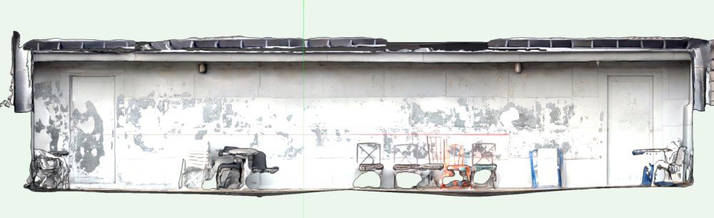
It's for sure more than an aid for rendering. In this example, a two or three minute scan in combination with the Clip Cube gives and excellent status report of how well the floor drainage is working, as you can clearly see the angle of the floor towards the drain well. A better scanner, such as the Matterport would probably give a better result, but it's never an absolutely correct result. It should also be pointed out that a conventional laser distance measuring device also comes with a degree of errors. You can try it by scanning the distance between two seemingly flat walls. Just tested my Leica at a distance of about five meters and found a fluctuation of 4-5 mm in a series of ten measurements at the same location. That equals to an error margin of 0.1 %. The main flaw with laser and ladar measuring is that it does not know what is important and not. Having thousands of measuring points on a more or less flat wall or floor is a bit pointless. We as humans can instantly see where the shape actually changes, and we can therefore instantly reduce the number of measuring points to an absolute minimum. I did a lot of boat cover designs a few years back, where we tried all available methods for scanning. On a boat cover, you are not really interested in the panels as such, just where the edges are located, and this is where point cloud measuring is pretty useless. We also tried a Dutch wire based system (very expensive) and found that the internal precision it required to make it work made it drift and becoming unreliable after a while. The best way was actually to use photogrammetry using user defined measuring points. Photogrammetry uses a series of pictures from different angles and where the program compiles the data into a small number of 3D points that you can skin. A conclusion is perhaps that each of these devices have their strengths and weak points. Laser/Ladar works best on flat of gently curved shapes, but having problems with finding precise corners. In a house with flat walls, you can use the wealth of similar points to identify a wall or floor and then let the CAD program find the joints. The trick is to find the right combination of tools for a given task.
-
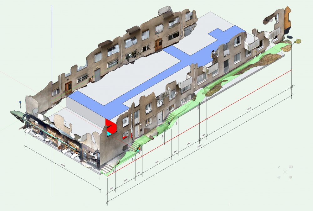
My guess is about 1%. Heights are a little more accurate. You can't measure something like a kitchen for production design where you cut everything to measure, but it has proven invaluable as it gives a lot of details and where they are located. Great for creating cost estimates. In the example, one of the tasks where to locate plumbing and ventilation, where we did not have any documentation at all. The architectural drawings from 1939 where a bit sketchy and the building had some changes made over its 80 year plus lifetime. I'm actually surprised how useful it has been scanning with the phone, and I suspect every contractor will have something like this in their standard tool set some time very soon.
-
Here is a compilation of about 25 scans direct imported into VW, and used for documenting a building in combination with the technical drawings (not shown here). The scanner used was an iPhone 13 Pro equipped with the freeware Scaniverse. The resulting file is about 600 Megs.
-
On the subject of argumented reality, I have tried Adobe Aero, and it seems to work with files from VW, TouchCAD, Scaniverse and Keyshot on both the Mac and on iPhone. The picture is from an iPhone.

-
Loft keeps making groups instead of single NURBS
Claes Lundstrom replied to techdef's topic in General Discussion
It's not 16 curves as such. It does indeed work If you make one simple curve and duplicate it using Duplicate Array. So the shape is most likely the key here. I think the underlying 3D engine simply thinks your shape is too complicated to work, for example overlapping itself or something like that. -
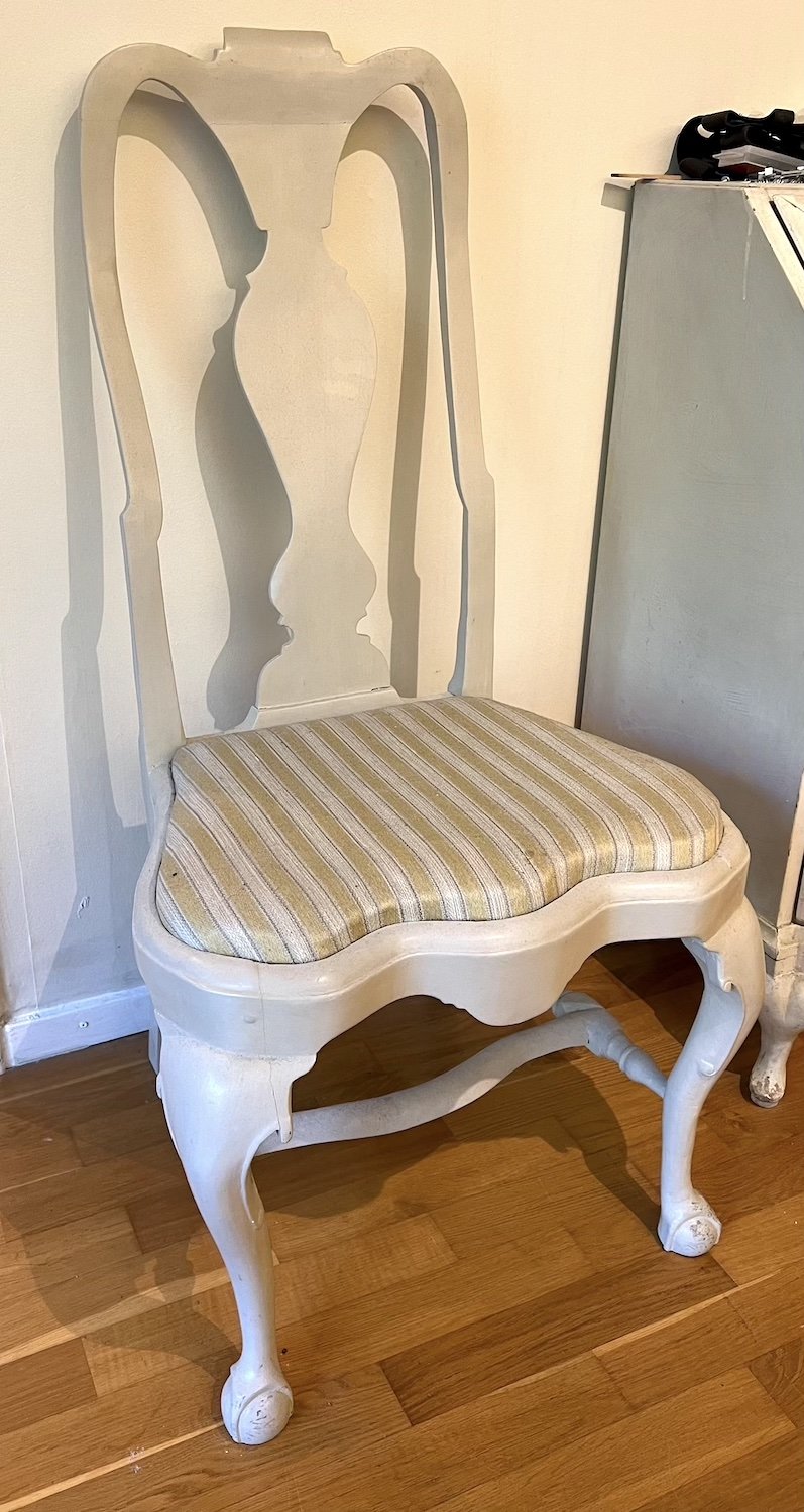
The biggest limitations when scanning objects with an iPhone, such as the Eames chair, comes on the skinny parts, for example the foot and armrests. Bigger more solid chunky objects typically works fairly ok I would say. In my example, a 250 year old chair, the seat works fine, whereas the skinny and more intricate parts fail. The problem with it is of course the combination of being skinny and having a very intricate and detailed shape. Another disadvantage with scans in general for a symbol is that the model becomes much bigger. A good symbol should always have as few elements a possible, especially when you insert many on a bigger model. Keep it as simple as possible while maintaining a recognizable shape. Scaniverse.mp4
-
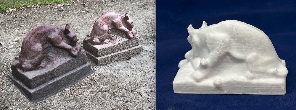
On the phone level, it can not be used directly to measure for example kitchen cabinets. It's simply not accurate enough for precision measurements. It is however useful for quick price estimates and an excellent piece of documentation. Another major flaw with scanners is that they generate huge files where almost everything consists of junk info. As an example, imagine a very simple table model, represented by an extruded rectangle representing the table top and four small extruded rectangles for the legs. The parts can be defined mathematically by a very limited number of coordinate data. Most scanner software on the other hand, needs to measure a huge number of points just to be able to estimate where the key data points (the edges) are located. The fundamental difference is that the human computer can instantly figure out where the edges and boundary are, whereas most scanner software can't. On more organic shapes things swing a bit towards scanning. Manual modeling can still generate much smaller models, but it requires way more skill and craftsmanship to get there. The example is probably beyond what most CAD designers could achieve and it would take quite a lot of work. The scan took less than five minutes with an iPhone 13 Pr. The result is surprisingly similar to the original (the picture to the left was placed next to the original within the scanning software). The model was also accepted without any problem by the 3D printer software and came out fairly good on a simple $200 3D printer.
-
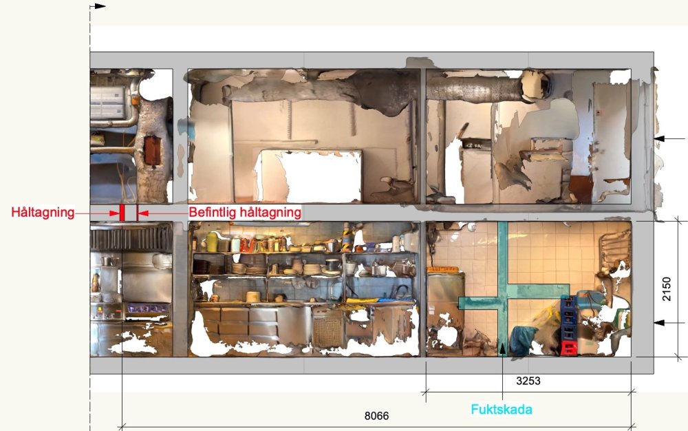
I have used my iPhone too and found it quite useful. In this example, I tried to illustrate potential drainage problem against a house wall. Here is another example where I made sure it was safe to drill a vertical hole in the middle of a lot of piping and equipment, by placing two different scans from two different floors on top of one another. Note how well the walls aligned.

-
Mesh Conversion and Facet generation density
Claes Lundstrom replied to The Hamma's question in Wishlist - Feature and Content Requests
I think meshes are what the are, and are not really affected by these settings. NURBS based models are different as they enable you to calculate pretty much any mesh resolution / smoothness within a given surface, though in VW it means high, low, and medium rather than using numerical settings, and as a universal setting rather than an object specific setting. The picture shows an example from another CAD program, where such settings exist, and where one side consists of 28800 quads and the other side of 81 quads, and I can individually change it back and forth at any time and when I need to. I personally find such settings invaluable. Technically, there is no reason why VW could not have it too, but there isn't.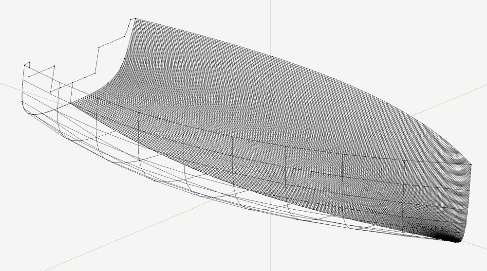
-
Generate a separate rendered water surface that looks like thet type of water you want, and use an extraction of that as a texture map in the shaded version. It will of course not look as good as a full rendering, but the Shaded mode was not intended for that type of use.
-
Scaniverse is also my absolute favourite after have tested several similar programs. Scaniverse works very well with VW in several file formats. Using a points style format works best for terrain models. I mostly use OBJ for textured models though.
-
Accuracy is, according to their web site, +- 0.5% on a 12 ft long line, so +- 18.3 mm. So, in my experience it does not seem better than the lidar apps I have used for the iPhone 12/13 Pro. Seems rather expensive relative to what it does.
-
I agree that it would be very useful to be able to control the number of points (beyond high, medium and low), and exact behaviour of a given curve. In my main 3D modelling program, I can set it locally for each given element, part of an element, and numerically to whatever I find relevant for any given task. I find it extremely useful, and could probably not live without it for my type of work.
-
Have done a lot of such work. The problem is often in the other end, that is, many of the programs used for controlling CNC machines have severe limitations. The software is often simplistic and often ageing. I therefore suggest keeping geometries on a very basic level. In 2D, it typically means using lines, polygons, and arcs to define things. Avoid Berzier and spline curves. Avoid symbols and groups. Avoid using filled surfaces, and for example using Clip Surface to define a hole in a closed polygon/polyline shape. On polylines, only define shapes using straight lines and arcs.
-
I think the liar is the same on iPhone 12, 13 Pro and iPad Pro. It's basically a matter of taste using a smaller or bigger screen vs how easy it is the bring it along at any give time. A smaller screen works fine for me tough. I have the bigger iPhone 13 Pro model.
-
There are many apps on Appstore doing this. I checked five or six and decided on Scaniverse as my personal favourite. It's also free, believe it or not. Is it difficult to use? I bet you will get something reasonable good out of it in your first try. It's fairly similar to creating a movie. You get white and red stripes where it still misses data. Just move around with gentle movements and watch was happens on the screen. You need to practice a few times to know how to get the best result, but it's fun and easy. Skinning the model takes a few seconds, in any event less than a minute, after which you can look at the result on the screen in full 3D, including spinning and zooming. You can trim and rotate the model in the app, and even generate a movie or a still shot from any view. Then save the model if the preferred format. I have a Mac, so a quick Airdrop from the iPhone or iPad is the quickest way to export to the Mac. Takes seconds. OBJ gives the best rendering, whereas PLY works best for Digital terrain models. The Ply importer allows you to define the number of points to be used with a slider. Lower res may be good enough. It's a bit like using a well used piece of soap instead of a new one having sharp edges, or using a more or less blurry image to represent the shape. In VW, you import OBJ as OBJ and PLY files as a Point cloud. The sample model contained 469204 points.
-
Though I would try the other formats supported by the iPhone scanner program. Besides OBJ, it also supports PLY and FBX. Not sure about FBX by this is what came out of the PLY version, when converted into a Digital Terrain model. The model was about 7 megs. The input as such was not as pretty as the OBJ, but the DTM thing working is a plus. Of course, it freaked out a little by the house and resting walls and where there was a steep rock wall, but not bad. Measurements seems t be right too. It only took a few minutes to get to this, plus the five to ten minutes it took to scan the site. Not bad for a phone? I even managed to include my feet here and there by scanning myself.

-
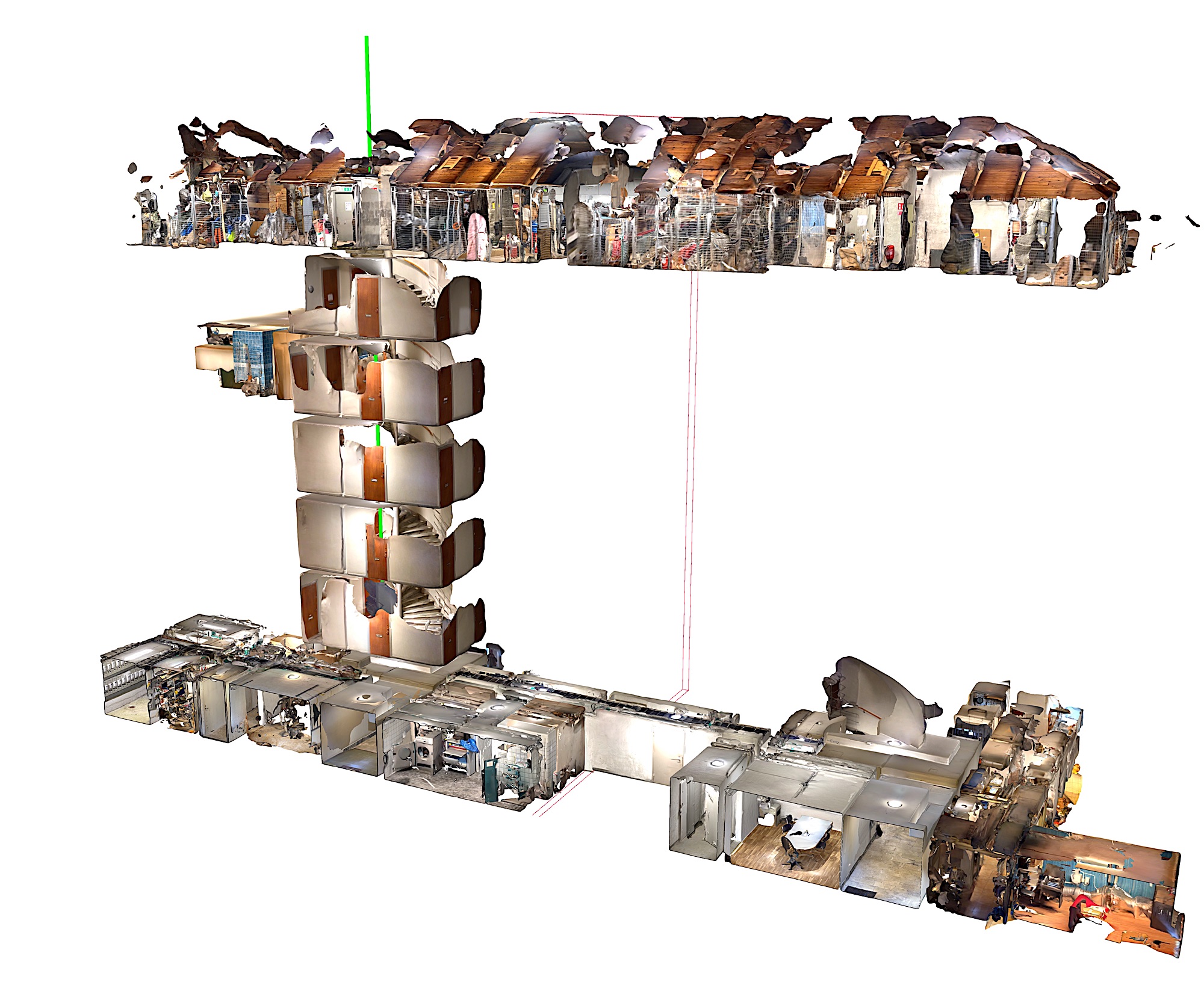
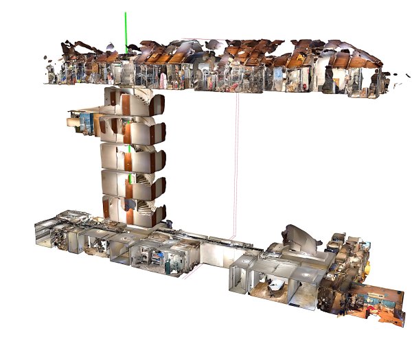
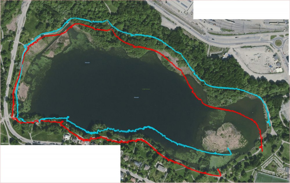
The scan was more like 10 minutes. You don't get mm precision, for the most part more like within say 10 cm. Heights seems to be more accurate for some reason. To check I measured a seven story stair, and compared it to the real heights and the heights where off by something like 2-3 cm, so the fluctuation was not clearly distinguishable from fluctuations of the eighty year old concrete house. At the most heights where possibly short by say 2 cm on a 2.7 meters height of each floor. The scan was essentially done by walking from the top downwards in the stair, at say half the speed I normally use, while gently moving the camera back and forth. Time, say five minutes at the most. The picture shows a hybrid of scan and measurements. The back side drifted a little in shape due to bad access to a corner. When scanning large objects, it's important to do it using slow and gentle movements. Limitations. The lidar can only measure up to about five meters, so tall buildings are impossible without a drone. Size, just to mess with it, I had a walk around a small local lake, having a circumference of about two kilometers, As you can see from the second picture, it started to get lost about half way around it, but when I made a copy of the cans and rotated it around the point where it got lost, the second part actually worked fine. I placed it on top of a satellite map and the result was surprisingly good, considering that it's not really a measuring device, it's a PHONE. I checked regularly against the water surface to see if it drifted in height, and it basically didn't. It also freaked out completely at about 1.7 of the 2 kilometers, though the data wasn't lost. It just slowed down to a crawl.
-
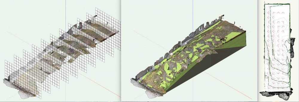
I used the this manual method as VW does not seem to like meshes having a couple of hundred thousand triangles. As I mentioned, I generated a flat rectangular 3D polygon and used that as a working plane. The trace takes place that the intersection between the flat plane and the 3D model, a bit like something sticking up on a water surface. I started at the lower corner of the house with Z = 0. I then went to the top (not top plan) and traced the contour around the intersection between the flat plane and the 3D model using OpenGL rendering (or whatever it's called now). I used 3D polygons but it can just as well be 3D loci. Also important to do the tracing in a different layer with no intermediate snapping going on, as VW then freaks out completely. Once one level is done, you simply move the flat plane up some distance, in my case I used 0.5 meters, and traced it again. Remember to move the working plane to the new level. Etc. The result was indeed a site model. Details such as trees are easy to insert when required.
-
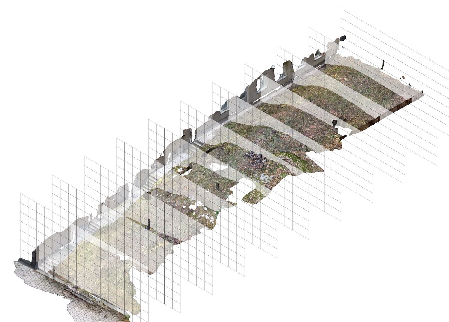
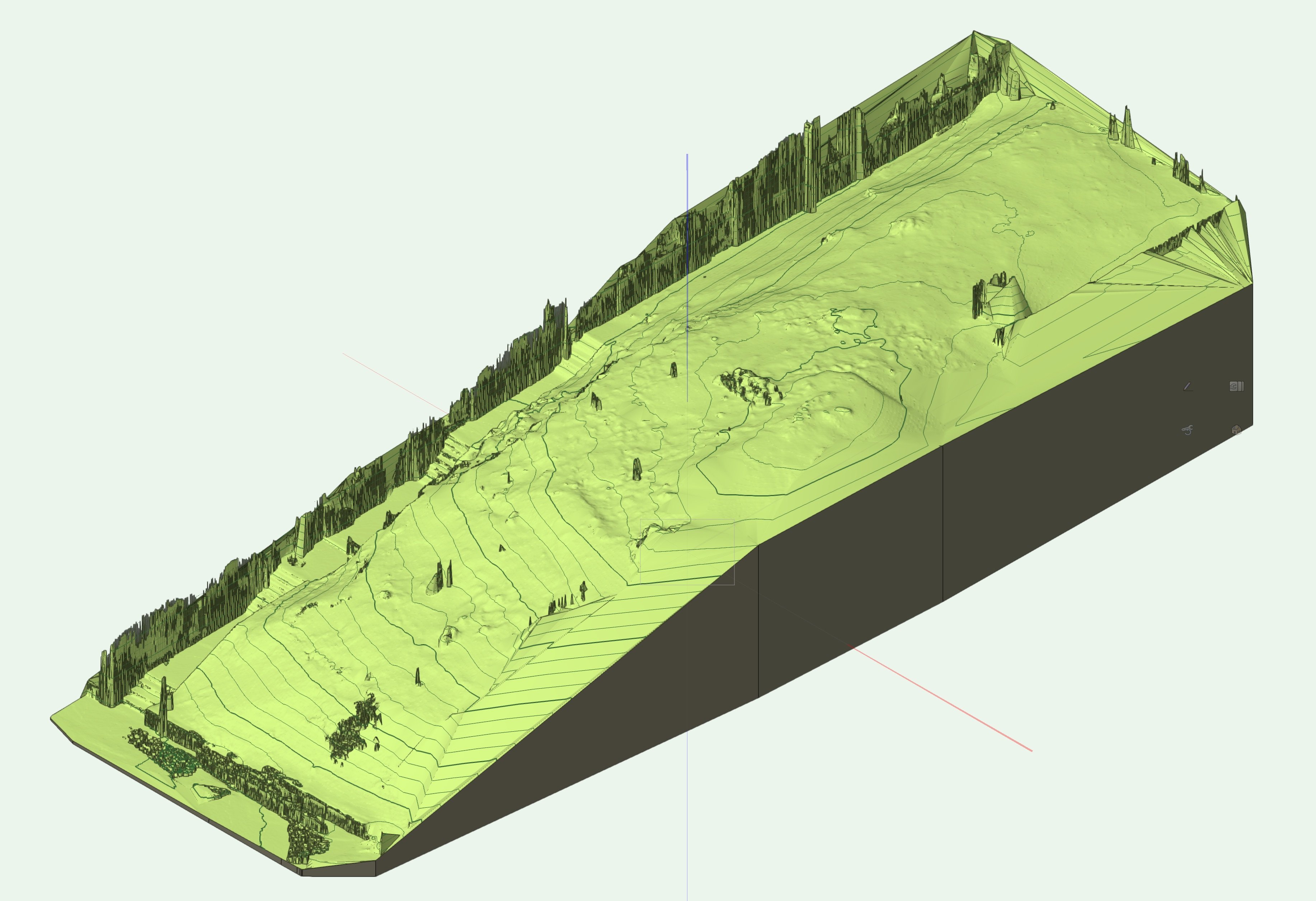
My comment was perhaps not intended to be all that seriously for city planning 😉 The iPhone can be surprisingly useful for smaller projects. The movie was just for fun and was actually created by the iPhone program itself. The purpose of this scan was to analyse a drainage problem on a 30 x 15 meter area. The scan took say 5-10 minutes as the site was rather steep and slippery. The model imported fine into VW though I hade to fit the YZ from this particular program. Converting the model to a DTM seemed to take forever, so instead I placed a plane at a given height and traced the intersections manually in a separate layer not using snapping. I then moved the plane a given distance and repeated the procedure until I got a series of 3D polygons, which was used for creating the DTM. I also did an illustration of the shape using a series of vertical grid surfaces to visualise the shape to the non technical people.
-
... or you can use a poor man's drone, an iPhone 13 Pro 🙂 and Scaiverse Poor Mans Drone.mp4
-
Exploded View Tool
Claes Lundstrom replied to shorter's question in Wishlist - Feature and Content Requests
Would be good. I use it a lot..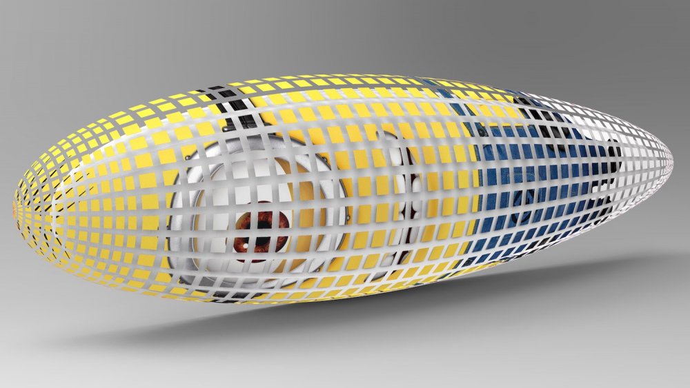
-
How do I create a shape from a series of cross sections?
Claes Lundstrom replied to Bruce Kieffer's topic in Solids Modeling
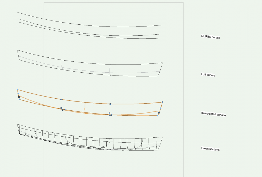
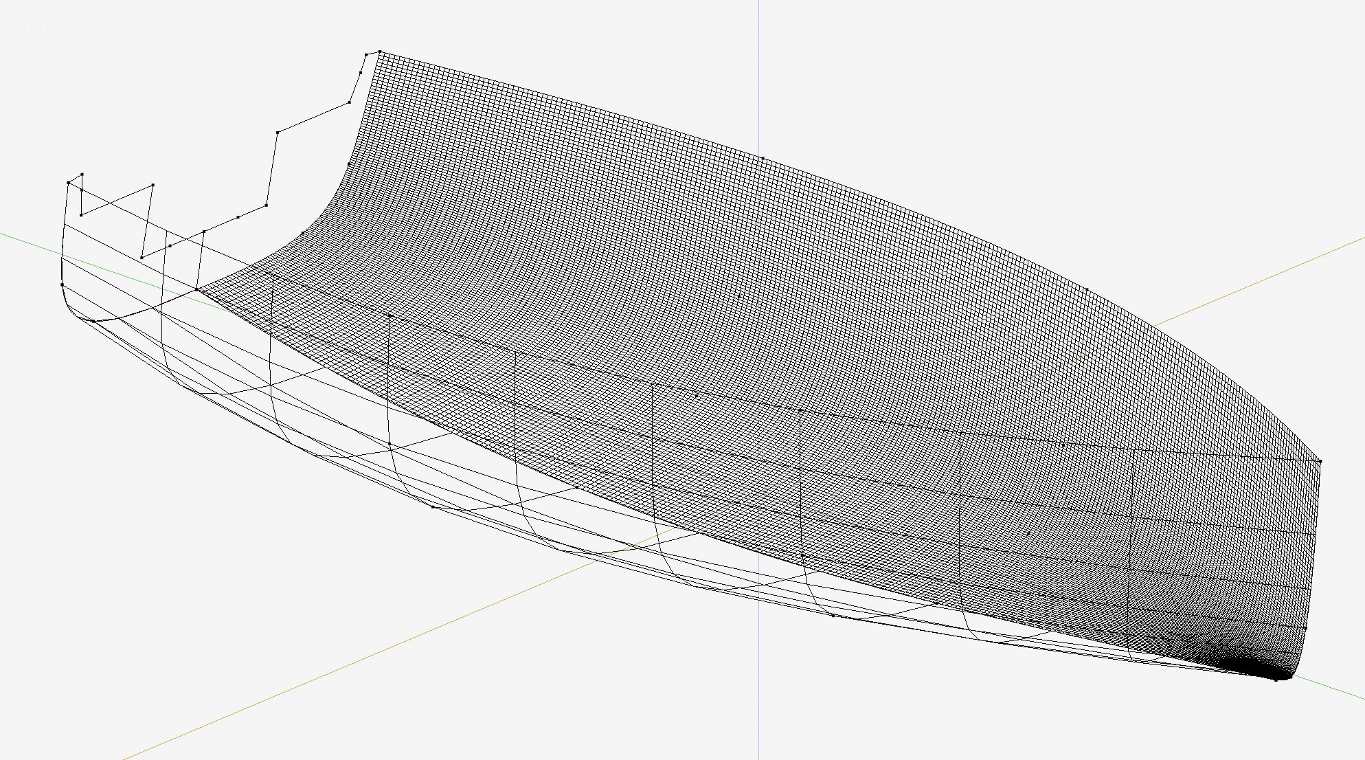
Using lofting of cross sections can be a nightmare in most NURBS based programs, and VW simply doesn't handle NURBS editing very well either, compared to most standard 3D CAD programs. No disrespect intended. VW's inability to nudge control points, and why you can't edit any number of control points in any number of objects at the same time remains a mystery. In my professional boat design program, I can easily tweak 500-1000 NURBS objects at the same time using a random selection of control points, and get an instant update of the lines drawing at the same time. Given the use of VW, you my consider using the following method: 1/ Generate some curves along the length of the boat, say three. 2/ Loft them into a a surface. Convert it into an interpolated surface having four by four controls in the grid (or thereabout) . 3/ Adjust the shape so that it looks reasonable. 4/ Add sectioning to see what the shape looks like. 5/ Repeat step 4 & 5 until the sections get close to the original cross sections 6/ Extract the cross sections to generate the updated buck shape cross sections.