


Claes Lundstrom
-
Posts
227 -
Joined
-
Last visited
Content Type
Profiles
Forums
Events
Articles
Marionette
Store
Posts posted by Claes Lundstrom
-
-
18 hours ago, jeff prince said:
in fairness to Vectorworks, this problem you are experiencing has more to do with the lack of quality on the model builder’s part than the software’s ability to import the file.I agree with Jeff. I never have any problems importing obj files from the source I use. Absolutely rock solid.
-
 2
2
-
-
15 hours ago, MartinBlomberg said:
So nice! Great stuff! Thanks!
This is my version.
-
4
-
-
5 hours ago, halfcoupler said:
Bought a HP DesignJet T650 24-in 6 Months ago. I call it my 'dancing machine' since it's shaking a lot when printing, but up to now, it works reliable. I think it's mainly designed for small business. I'm printing not more than 80 Sheets per week.
Yes you need a solid table, that's for sure.
Just shifted from a Canon TM200 to a HP. Way better and reliable. I hated the Canon from day one over the three years I have had it. Ridiculously fragile, over engineered, very expensive print head, and the worst drama queen ever, though printed well when being in a good mood and a lot of persuasion
-
17 minutes ago, VIRTUALENVIRONS said:
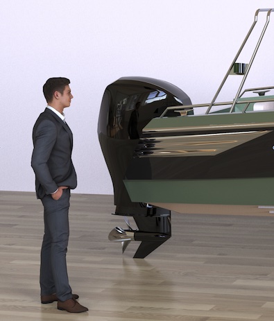
Hi Claes,
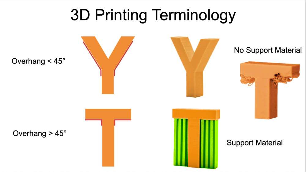
Beautiful boat, excellent. Although I only build for a company that does 3D printing, there was as you pointed out a learning curve. In particular on what a printer can and can't do. Below is a diagram I found helpful and speaks to your instruction.
What method do you use for connecting parts that were made in two parts?
Yes good illustration what I meant.
3D printing requires a special mindset designing for 3D printing, where you have to extract a way to work and how to split the model into parts, and finding a good orientation for the print. You just need to practice.
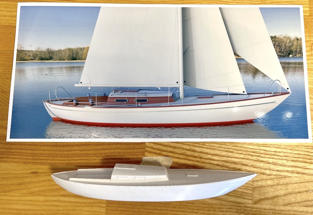
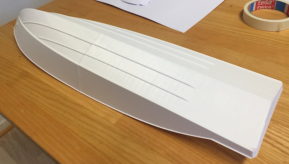
I typically glue the parts together, using a glue that can handle the slightly non sticky surface of thes plastics. On very thin skins, like the boat hull above having a thickness of just 1.2 mm, I typically add a small flange along the joint, and of course on the inside, looking a bit like a frame or bulkhead. This adds surface area to the glue joint, but also adds a bigger footprint towards the printer bed, which is useful as it is a skinny shape relative to the mass that moves around above, and therefore risks falling over when the bed moves.
-
On 3/23/2023 at 6:29 PM, FBernardo said:
@Claes LundstromThanks for the help, although what I was looking for is more of how to best prepare the vectorworks model to be exported to 3D print it
Like how to try and improve the windows so it doesn't go so slim or even the walls, the software will scale the building properly but the windows will become too thin... I wanted to create a set of rules and settings so I can share with everyone in the office so they can print easily without constantly being present.
There are a few basic rules that are useful to follow, assuming that you are using an extruder style printer with a single extruder so that you can't add supporting material that you remove in a step 2:
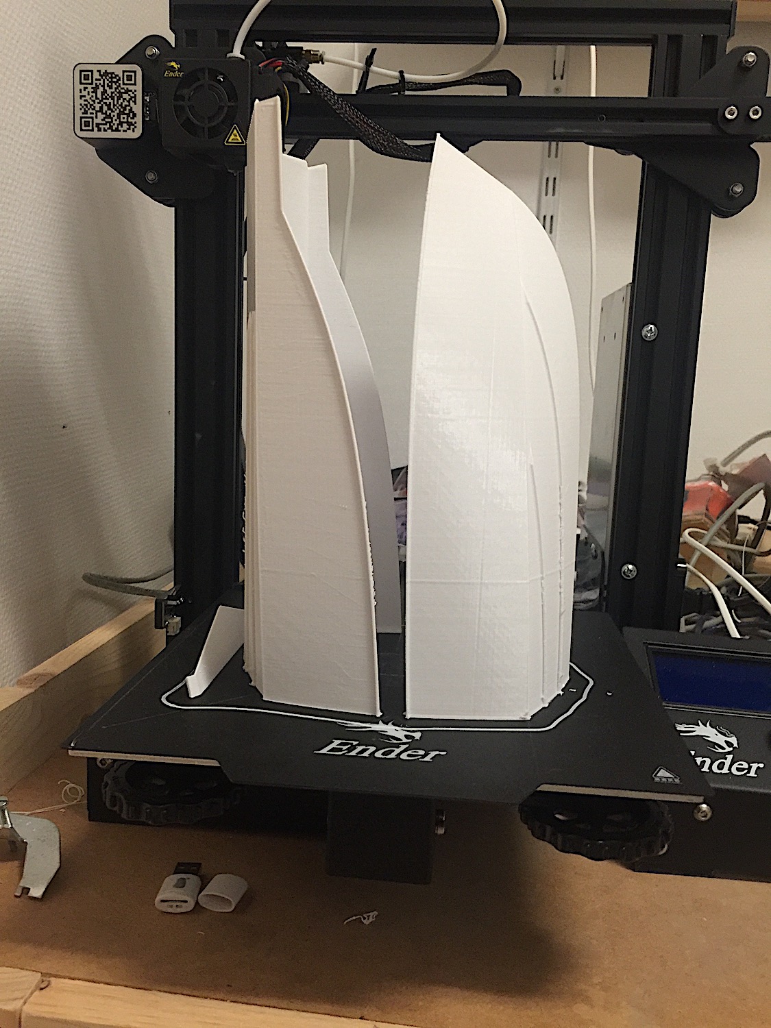
1/ Make sure that you have enough thickness. On my fairly basic printer, I have found that 1.2 mm always works. In my boat example, the contractor wanted 5-6 mm on the full scale model (about ten meters long). When I scaled it down to fit my printer having a build height of 250 mm, and printed in two parts giving a model height of about 500 mm, the material thickness fell below 1.2 mm, so I had to produce another model with thicker walls relative to the full scale model.
2/ For single extruder printing, the rule is to avoid angles exceeding 45 degrees. Imagine building something out of dry sand. If the angle is too steep, it will simply collapse. On my boat example, I had to find a setup that avoided thes 45 degrees. Standing on the transom would not work as it leans outwards 12-14 degrees, which would make the model fall over. Splitting it along the centerline and printing it in two pieces lying on the side would not work as the sides would exceed 45 degrees by a wide margin. The solution was to split the model in the middle. Each part could then stand up without any problem, and I could double the size of the model. The transom and two plate was however a problem, so I printed them as separate parts with joints at an angle to to hide it as much as possible. On a house, you can think it a similar way. How can I for example print a roof having a flatter roof angle than 45 degrees? You simply print it as a separate piece standing up on the side, or for more complex shapes, you can ask yourself if it's possible to split it in the same way as I did with the boat hull, so that you manage the angles and can maintain a shape that stands without falling over. Windows and doors can of course be a problem if you want to print it with see through properties, but you can print a wall lying down instead ?
3/ How can I check if a model is a true solid model, and would therefore cause a minimum of problems? The basic criteria simply means that the part or parts all consist of closed shapes. If you still have a problem, you can check if the normals all face outwards. A quick test is to convert a given shape toa mesh and then calculate the volume of it. If you do get a volume, the model is most likely correct. If not check closed shapes and volumes again until it works.
3/ You can of course print a house model as a solid object, having a mesh inside but it does have the disadvantages of just being an exterior and it would also take longer to print. It would therefore probably make sense on very small models representing volumes instead of being models looking like real houses. Below is an example of a solid print, that is, it's filled inside with a mesh structure.
-
1
-
-
10 hours ago, Tom W. said:
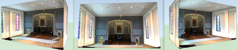
@Claes Lundstrom did you stitch these 25 scans together by eye or is there a more precise method for aligning them within VW?thanks
It was a combination of drawings, laser measurements, and scans, where I tried to merge them into one unit. The house was built in 1939, where architects did not have VW to work with, and nothing was done in 3D, so even the drawings had to be cross checked against one another. The house also gradually changed over the years. As you can see there are a lot of factors that had to be merged into one 3D model.
I have to say that I have made good use of these scans since my posting. I used it for locating sewage pipes in the house as it is time to reline them in the basement. For some reason we could not find the original drawings, but using combinations of scans from all seven stories, I was able to generate a good picture where everything was.
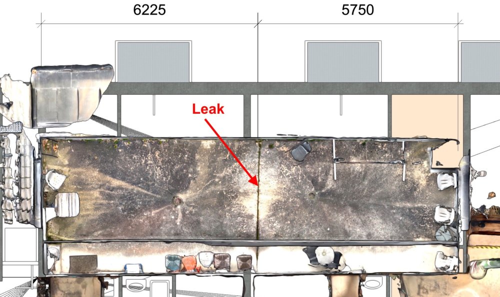
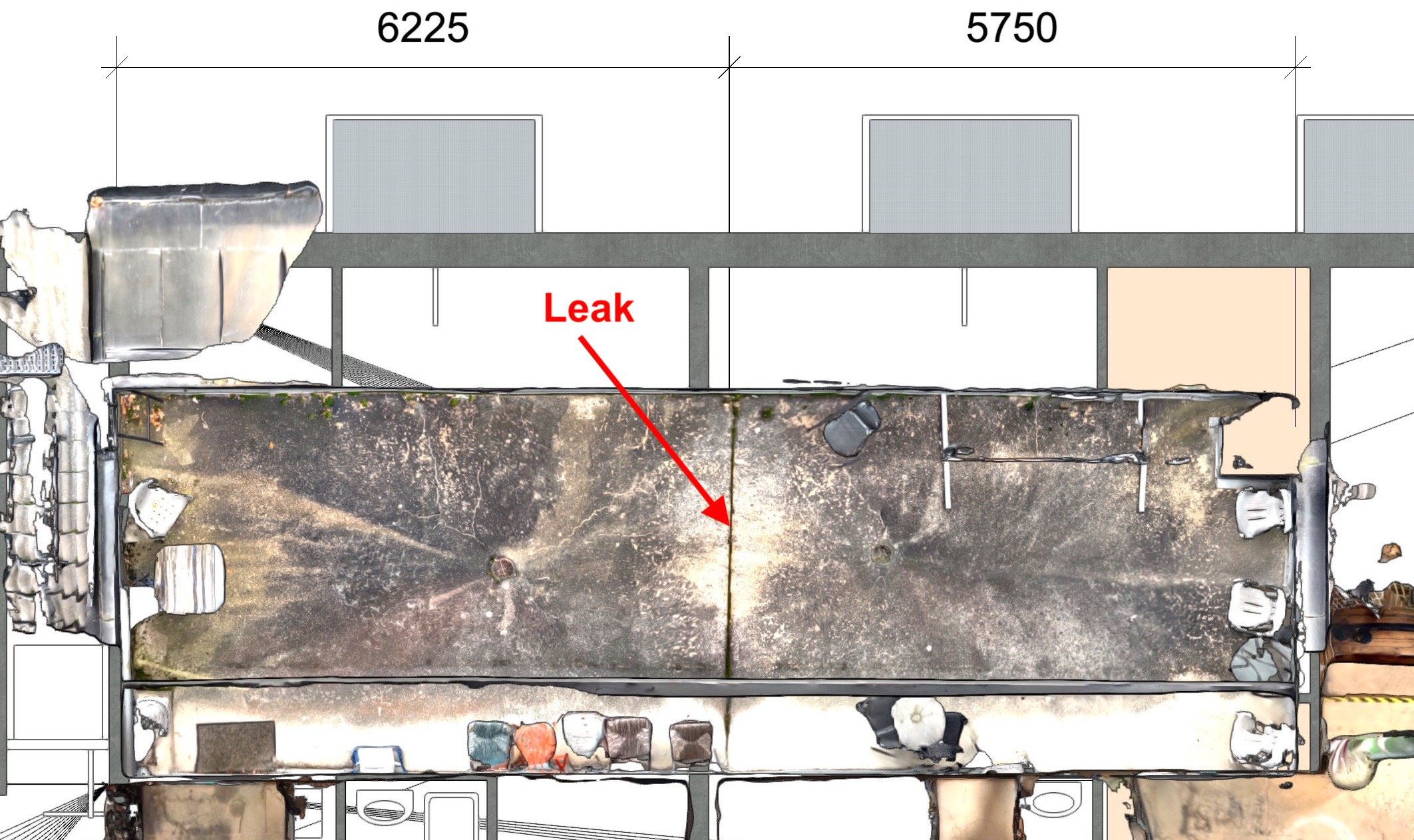
Another example was a leak in a terrace, where a joint turned out to be the problem. I could place a scan of the terrace on top of the plan drawing below and it became obvious what the problem was. I even double-checked the measurement with a Leica laser, and the scan was 14 mm off vs the laser scan over 6.225 meters.
-
3
-
-
1 hour ago, Tom W. said:
So was this done outside of VW + brought in...?
It was done outside VW and brought it as I have quicker way of doing it.
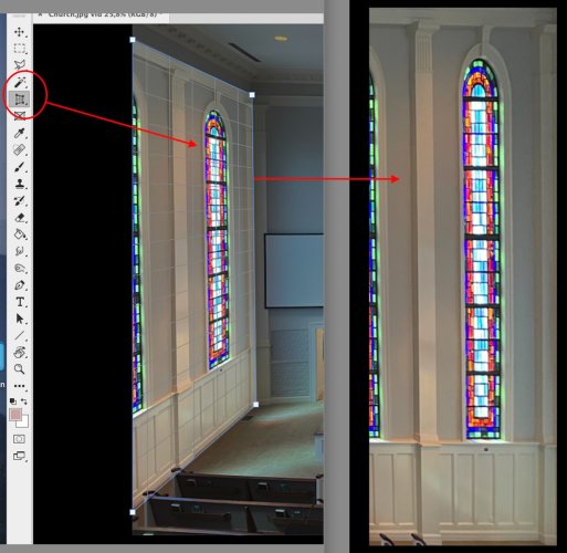
My point was however that you can do it in VW too. On a basic level, you can for example use the Photoshop "perspective killer" tool (or whatever it's called, and generate a picture for each side, create a RE texture for each side and map it the five respective sides (used in the example).
-
1
-
-
You can extract a crude model using basic UV-mapping. Here is a quick and not very ambitions example. I have no clue about the dimensions of anything, so it needs tweaking everywhere. It would also look better if I added parts for the podium, so this is just a simple example. Lightning also needs work.
-
3
-
-
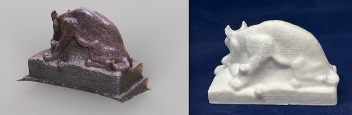
OK just wondered. Scanned some granite sculptures in the past with fairly decent results but they don't move much do they. Even 3D printed fairly well.
-
2
-
-
9 hours ago, jeff prince said:
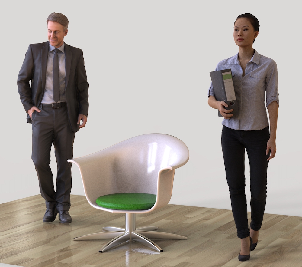
have you tried Poser?Have you tried scanning people with your phone ? I suspect that many of the photo realistic figures shown in previous discussions are just that. If it works, you get exactly what you want in poses and dressing,
-
2
-
-
12 hours ago, Kaare Baekgaard said:
I am somewhat honored to be rebuked by the great marine designer and creator of TouchCad 🙂
Would it make sense to send a resumé and portfolio?
I wasn't talking about your design. Nothing wrong with that.
My point was that almost all developers of CAD programs, from SolidWorks and Catia and downwards, tend to use boats as example of what their products can do. In reality, there is a huge difference between generating something that looks like a boat, and generating a fully functional and production ready design that works well as a boat. Boat design is basically a wide array of elements that you gradually compile into a finished product, such as lines, weights, hydrostatics and stability, production friendliness, etc. You start with a basic concept, and then gradually tweak the parameters, often in very small steps, until you reach a good final result. The dedicated boat design programs do this as an integrated elements, which simply makes it a lot easier and quicker to get to the final result. You can repaint your house with a screwdriver, but why bother when it's much quicker using a brush.
-
2
-
-
8 minutes ago, Kaare Baekgaard said:
VW nurbs are a lot better than given credit for by architects. The attached dinghy looks smooth, because the surfaces can be controlled perfectly.
I would love to see Rhino inside, though, and I am jealous of some of their tools. The Rhino import is , because all I get is millions of unhinged, ungrouped surfaces.
8 minutes ago, Kaare Baekgaard said:NURBS are better in Rhino, though as an old boat design pro, I would never use it for boat design, despite that it's probably the most commonly used program for small boat design. In my opinion, it's really not a boat design software as such as it simply lacks the essential tools. You can add boat design extensions like Orca, but after having tried it, it felt way too much like an afterthought.
-
Imported correctly into Keyshot if that helps to know.
-
2
-
-
14 hours ago, jeff prince said:
I'm curious, what are you basing this "most users are in 2D" statement on?
I was in manufacturing engineering over 25 years ago, and 3D was required for I.D. and Mech to get a job in industry... Pro/E and Catia were the things to know if you wanted a real job in manufacturing. Computer modeling, CAM, 3D printing, CNC, and EDM were mature and robust tools at that point.
The AEC industry was slow to adopt 3D, but that was even common in big companies and government such as Federal Highways and state DOTs in the mid 90's. Even sole proprietor architects who plan on being in business for the next 10+ years have largely moved to Revit or similar. Ironically, BIM has its foundation in Pro/E and Catia, if you want to know the future of Architecture, look back 30 years at the history of manufacturing.
The kids coming out of school for the past decade are largely taught Rhino and Sketchup as a primary design tool. 2D has pretty much gone the way of the Diazo machine, and that seemed to happen overnight. Landscape Architects and Interior Designers are usually the very last to embrace technology, and even we have slowly been incorporating BIM and 3D into the majority of our work. The only work product that seems safe to stay in 2D is the illustrative sketch, but even that is threatened by Procreate and such amongst traditionalist.
You are a self proclaimed "3D NURBS Modeling Specialist" who has worked for Vectorworks, yet you do not know where Vectorwork's modeling kernels and tools come from? I was under the impression that everything Rhino and Vectorworks uses was licensed from SMLib and Siemens with regard to NURBS and Solids. I could be totally wrong on that though.
If Vectorworks bought their NURBS core from Rhino, why does Vectorworks drive like an old jalopy held together by baling wire and duct tape compared to the highly tuned Rhino 😉
I'm 100% certain there will be another great disruption to how AEC projects are digitally delivered within the next decade, especially if there is another global recession. What we are doing today will be archaic by then.
Unfortunately, I have to agree with Jeff. Vectorworks needs a serious update of its NURBS abilities. It hasn't evolved much since it first occurred in Vectorworks 9. Basics like for example that you can only work on one object at the time, and you that can't nudge control points, like you can with mesh objects, makes it hard and time consuming to do serious work with it. I don't think the Siemens Parasolids is to blame either, as other programs based on Siemens Parasolids can indeed do it. That's why I pretty much never do NURBS modeling in VW. I import it all if required (though not from Rhino, so don't have an opinion on that subject).
-
1
-
-
It used to be very easy to do in earlier versions of VW, but for some reason it was removed for some enigmatic reason, and was replaced by something way more complicated. A simple spin, and a basic back and forth motion should be a pre-defined settings in my opinion. It's by far he most used presentation I use.
-
1
-
-
29 minutes ago, VIRTUALENVIRONS said:
Thanks for the info. You have quite a stable of products. I take it you must do more than Architecture.
regards....Virtual
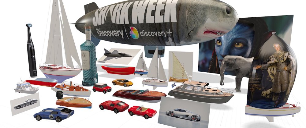
Some architecture too but nowadays mostly other stuff. Here is a random selection of models from TouchCAD dumped into Adobe Aero just to see fit it worked. It did. Got bored after 25 models and gave up.
-
1 hour ago, VIRTUALENVIRONS said:
This is just a curiosity inquiry. I always export from Vectorworks, but seldom import.
It appears that you and others model in two or more applications, Vectorworks and others.
May I ask what application you or anyone else on this thread use.
It doesn't bother me using several different programs, where each program simply works best for me and what I do, and takes me from A to B in the quickest possible way. I almost always use TouchCAD for my NURBS modeling, more advanced texture mapping tasks, high quality image unfolding, and for advanced unfolding/unrolling of complex panels. Vectorworks mostly for 2D documentation, building and construction modeling, processing scanned 3D-models, and sometimes when I need solid modeling. For basic renderings, I usually use the built in rendering in TouchCAD, whereas for more high quality tasks, I usually use Keyshot, occasionally Artlantis, and on very rare occasions Blender. Photoshop is always present of course, but also the Affinity range (Photo, Designer, Publisher). A recent favorite is Topaz Gigapixel AI used for pumping up the resolution of images, as I work with very large image files.
-
I agree with Jeff. .OBJ works flawlessly from my modeling app.
-
9 hours ago, Dave Donley said:
LiDAR is available in Nomad and now includes Room Plan, but also the Photos to 3D Model photogrammetry feature was updated recently to use Apple's Object Capture and it works better than before. Many photogrammetry datasets we have around that failed before now succeed.
Since for you the room is likely beyond the 5m limit of the iPhone LiDAR I agree photogrammetry would be what you should use. Give Photos to 3D Model a try.
https://cloud.vectorworks.net/portal/help/pages/capture-photos-for-3d-models/?app=VECTORWORKS
https://cloud.vectorworks.net/portal/help/pages/generate-3d-models-from-photos/?app=IOS_NOMAD
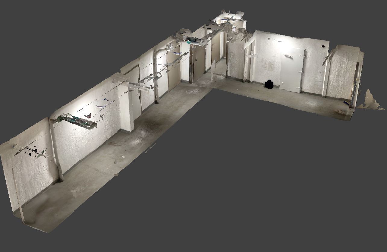
The 5 m limitation of Lidar assumes that you are unable to move, but that is not correct. I have always moved when scanning, which admittedly adds some errors to the model, but it does actually work fairly well. One problem is of course vertical scans, where the 5 m limitation is a problem for taller buildings. The enclosed example is way more than 5m.
Both photogrammetry and Lidar are therefore usable within their respective boundaries, and they both have their advantages and disadvantages. Scaniverse, which I have mentioned before, now supports both methods.

-
2
-
-
11 hours ago, FBernardo said:
Hi all!
We've been playing around with 3D printing some models, we can export correctly to STL using the ASCII option, although how would be the best way to improve the printing of the windows and as the nosel we have is 0.4mm and the mullions and framing is usually a simple dot which then looks terrible or fails!
any advice?
On the file format side, you can also try using OBJ files, which works just as well as STL on my printer driver software Ultimaker Cura. I can't verify it, but I guess it may be possible to print in color using OBJ too if the model has color and textures, and the 3D printer is a color printer.
For scale models, you need to make sure not to use thinner elements than the printer can handle. On my (admittedly modest but well working) printer, it seems to be around 1.2 mm but it can of course vary depending of the specifications of the printer. in the example, I had to make a special edition of the model, one for full scale 3D printing (model size 10 meters and skin thickness 6 mm), and one scale model edition, where the skin thickness was set to 1.2 mm.

-
3
-
 1
1
-
-
Let's face it, the unfolding features in VW are rudimentary at best. I'm a massive user of unfolding features on a high level, but over the years since it was introduced, I can't recall ever using VW for this. No disrespect intended, and yes I am a daily user of VW too.
-
7 hours ago, Ian M. said:
Have tried Polycam, 3dScanner, and Canvas on my iPhone 12 Pro.
Canvas has a service that will generate a variety of CAD formats...for a fee. I recall the Revit file being the most useful, but it still took work to make it a Vectorworks project.
Polycam has a "Pro" subscription that allows exporting files in a variety of mesh and point cloud files, but you have to do your own work to turn it into CAD.
3dscanner is free and allows exporting a wide variety of file types, so, being cheap, I use it the most, but I definitely have not worked out a good workflow for creating something usable. I would be interested in hearing which of the many file formats the Vectorworks community finds the easiest to work with?
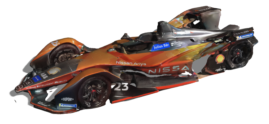
Scaniverse remains my absolute favorite as mentioned above in this thread, it's free, it supports both Ladar and Photogrammetry scanning, and it supports direct export of several of file formats that can be imported into VW including point clouds (for example used in terrain models) as well as fully textured models. It has also evolved quickly over time and the developer seems very eager to push it forward. It typically imports well into other programs, such as various rendering programs, Adobe Aero (both for iPhone and Mac), even Photoshop (the picture was scanned at an electric car show last week. A bit sloppy, yes, but I probably only spent ten seconds doing it, and only one run.
-
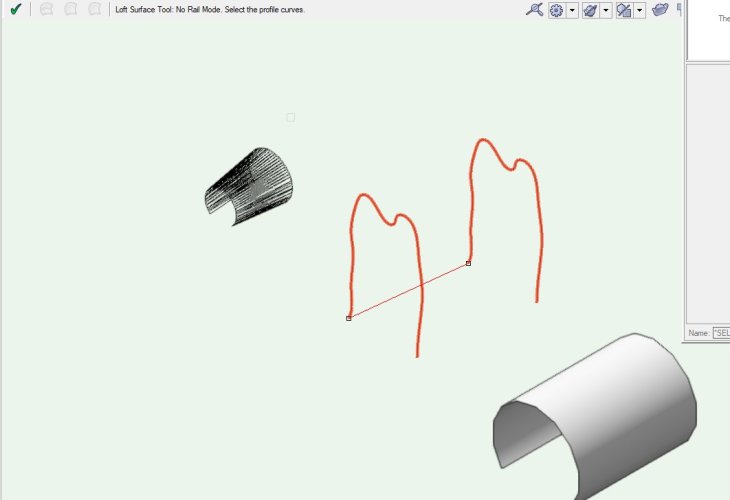
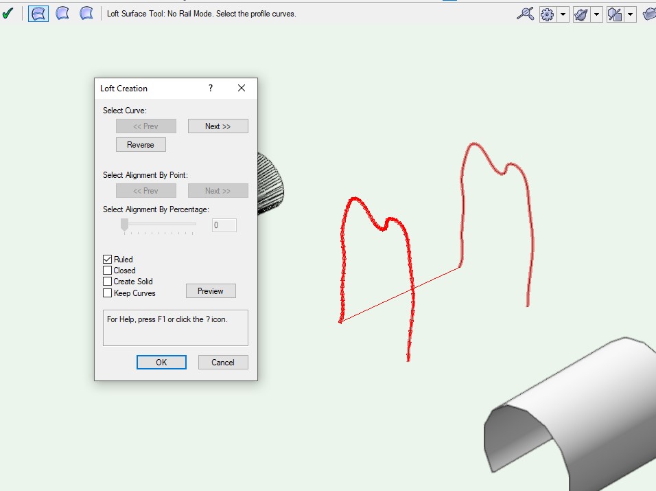
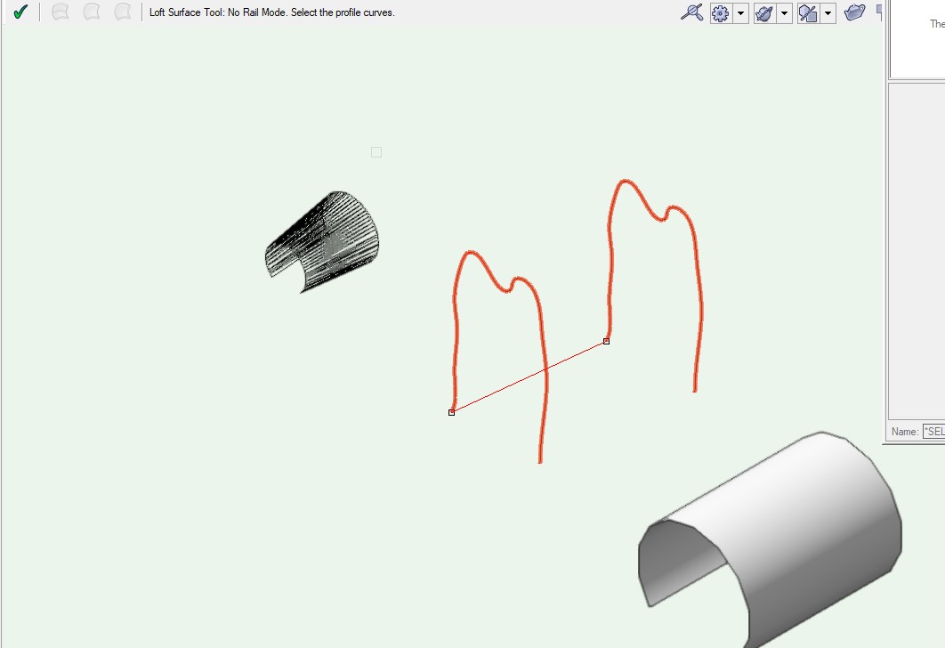
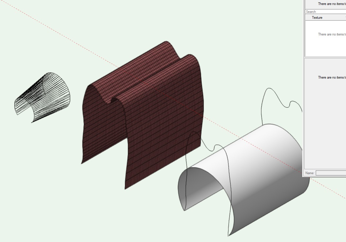
Looks like a bug to me, even though I never use VW for my unfolds. The only way to extract a predictable seems to be to extract two edge curves and then loft them into a new surface.
-
22 hours ago, AlanW said:
Hi I there must be something wrong with they were originally drawn.
Convert to 3D polys and then back to Nurbs and works fine.

I tried that and yes the shape is correct, sort of, but it's not a generic NURBS surface in the sense that it can be set to any mesh resolution.


Smoothing 3D objects
in Troubleshooting
Posted
Don't forget to convert the relevant to meshes if it's not a mesh. Otherwise mesh smoothing doesn't work.