
_c_
-
Posts
2,434 -
Joined
-
Last visited
Content Type
Profiles
Forums
Events
Articles
Marionette
Store
Everything posted by _c_
-
 Exactly.
 -
There isn't.
-
Data Manager - working in presets
_c_ replied to matteoluigi's question in Wishlist - Feature and Content Requests
It is. -
VW imageprops texture export issue or something more nefarious?
_c_ replied to Jeff Prince's topic in Rendering
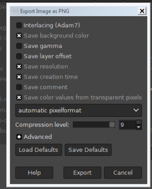
@Dave Donley, I am not sure if it is related, but I had similar problems with VB Libraries. On some of the images there was some sort of special mapping that could only be fixed with the Gimp disabling "Save color values from transparent pixels" during export. Perhaps it helps.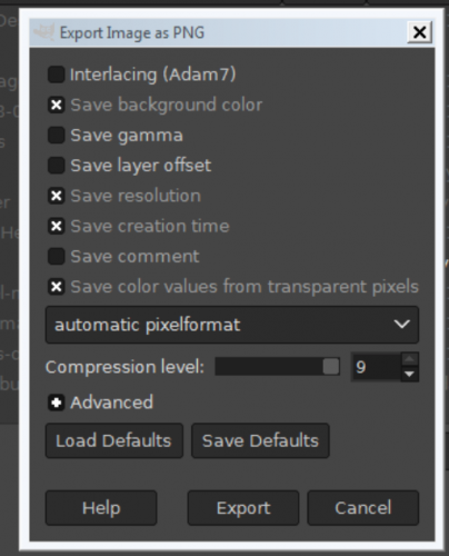
-
The geometry parsing itself would be very easy even for a novice, to fetch the proper sequence (which orthogonal line comes next) is not something that can be resolved simply. All in all if you have great many of such objects, you should indeed ask for someone to script it for you. I advise you against learning marionette or vectorscript it just for this task, because it is not a straight forward task that will bring you the joy of scripting, and that would be a pity. But if you want to get it going, ask in the Vectorscript forum.
-
No, someone will have to script it for you.
-
Select the lines Modify > Compose You should also be able to select connected lines through the contextual menu, after hovering on a line
-
John, this is the Vectorscript forum, you don't have to understand. Sometimes we don't either.
-
Raymond, I am always bewildered at your generosity, which, combined with your skills, makes it a true gift whatever you happen to do.
-
Yes. A few advises: name your Design Layer Viewports well, so you can easily spot them and mass edit them in the visibility tab of the Organization Dialog (which, for some reason, most users never notice). Preferably add a suffix, such as vp- or dlvp- Set the Viewport Class Visibilities to Use Current Document Class Visibilities, so you don't need to go crazy setting them up at every change. The needed elevation (Z) for the design layer with the geometry must be 0. The DLVPs can then be treated like any other 3D object. The Layer Wall Height (DZ) for the design layer with the geometry should match the standard height for your flats/floors. If you have multiple heights that cannot be resolved well. The Walls can be set to layer wall height, or whatever, it depends on your specific planning needs.
-
Thank you Hippocode, I did know your tool since 2017. I am interested in the process itself, I always prefer to develop my own tools, so that is easy to change whatever I want. I myself won't be able thus to enjoy your tool for this reason, but I think you did a great job there and will recommend it.
-
Same as TWK. Usually this is a set up taking a little while, yes, but it isn't done often and it pays off greatly.
-
No. Given that we don't know Unit Plan yet, presently the only really efficient way is using Design Layer Viewports. Both Symbols and Design Layer Viewports fail on variable wall height, obviously, but Symbols fail more, since their definition doesn't reside on design layer and walls are entities whose parent is required to be design layer. Edit: if you don't use walls, symbols are better.
-
We use design layer viewports. It is pretty complex if you need to display them on multiple files but it works perfect, including IFC export. This gets rather tricky if you need various wall heights. If Unit Plan resolves this, well done.
-
Glad to see finally components wrapping around windows, that was time. Materials as resources is good. I had my own command for managing this problem, glad to see this streamlined. I really hope that the architectural plug-ins get upgraded. I see no hint in this sense.
-
Very nice Hippocode, I might send you some clients. Would you expand on the exchange process itself?
-
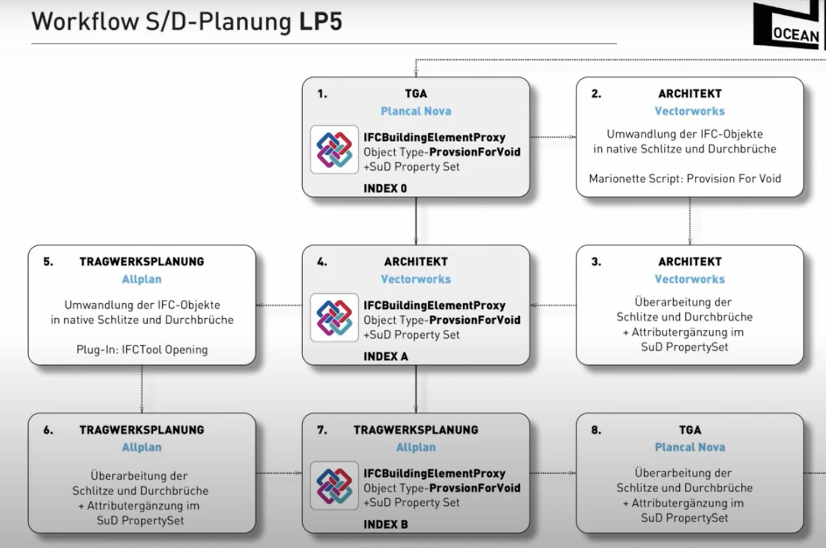
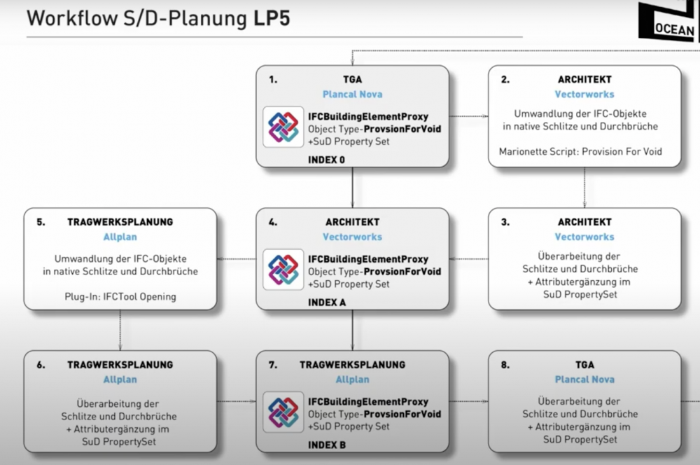
It is interesting the approach they take using three revisions 0, A and B. For those who don't speak German: TGA = MEP engineer Tragwerksplanung = structural engineer
-
Thank you! I didn't know that!
-
Ciao, the slab can get troublesome when the modifiers create detached parts. I would try removing the modifiers determining those rooms without doors, they are likely to be the culprit.
-
Ciao Nigel, I hope to have some feedback from people planning and managing IFC voids, the 2D part is not relevant, it doesn't require any particular tool. On the other hand, the management of voids in a BIM environment is major trouble and pretty complex. It takes a number of tools and commands. Ah, BTW, I don't sell them nor share any of it. But since I am quite off my expertise (I represent very well the banal architect), I am eager to learn from others knowing more.
-
Rex, keep your old machine and buy an used iPad for the internet stuff! I know of an engineer here that still uses Windows 3 or 4! Happy ever since. Doesn't want to change his perfectly functioning engineering software (whatever that is). And my absolutely most beloved and respected structural engineer (80+) writes all by hand and uses paper snippets and glue to change his documents during the project.
-
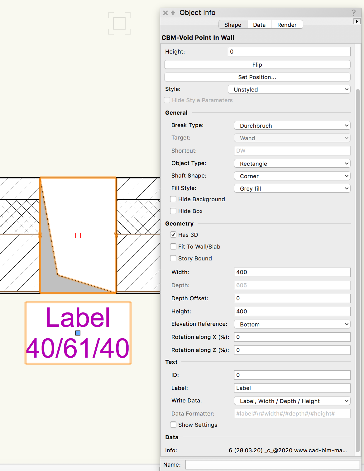
In an IFC project there is a point where one must exchange "hole" objects between architect, structural and MEP engineers. So any wall or slab which is cut because of pipes or whatever, gets "Voids". This can be a complex process. The void objects must be evaluated, rejected and/or accepted in a collaboration software. For this reason a wall hole is not enough. The holes are usually represented in plan with a graphic like the one in the screenshot below, this for some reason doesn't seem to be needed in USA, since VW doesn't offer such a tool.

-
Dear All, I am finalising a set of tools for Provision for Voids in Vectorworks. I would love to collect any kind of information about how you deal with these elements in your BIM projects. Share your experience, tell me your problems, tell me your recommendations. Thank you for sharing!
-
Hello, I will transfer the articles there soon, but I am not sharing Orso's subroutines any longer. _c_
-
Italy, then Spain, then France. Most hit right now. Warm folks with a habit of kissing and hugging. Bless our friendliness, it is killing us.