mark4
-
Posts
11 -
Joined
-
Last visited
Content Type
Profiles
Forums
Events
Articles
Marionette
Store
Everything posted by mark4
-
Not sure I know what you want me to send? The User/Library folder?
-
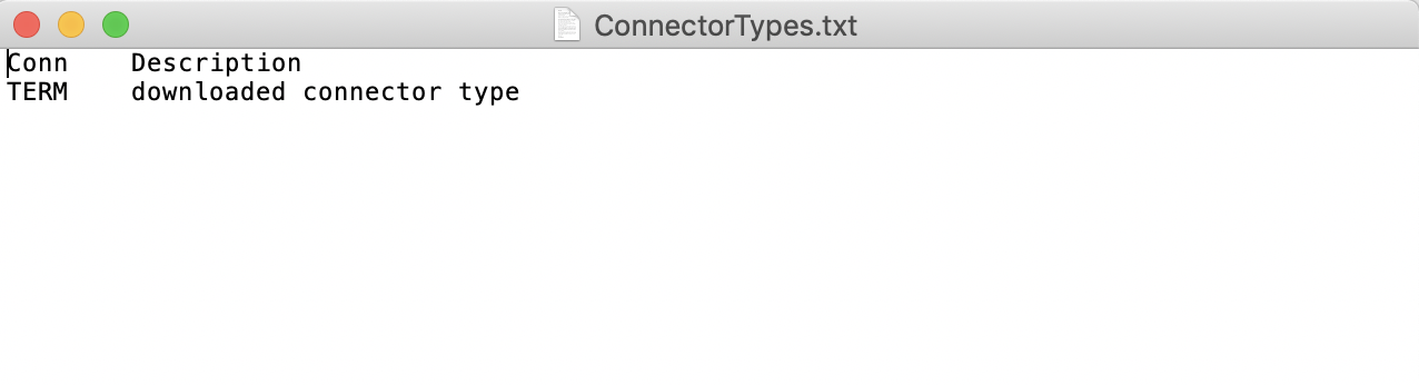
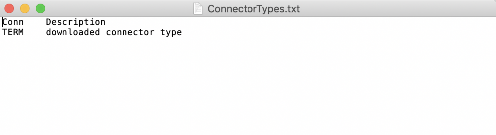
I migrated from 2020 to 2021 as well and can't seem to get my customized ConnectCad SignalTypes and ConnectorTypes files to transfer over. I copied them from the same 2020 folder to the identical 2021 folder (Vectorworks/2021/Plug-ins/ConnectCad Data). When complete and I open either folder, they both are empty as shown in the attached image. Despite this, when using the software you do see all the factory connectors and settings. Where are those coming from? So, how would I transfer my 2020 data over or even manually enter it all again? Thanks!
-
I have only been adjusting the Offset, not the Grid Spacing. Let me work with that to see if that corrects this. Yes, what I see in your pic looks great. I am just trying to identify what is "off' in my settings. As for my comment, I think it was taken a little out of context. I'm sure we could both agree that having text crushed together does make drawings look bad. That is all I meant. And I know this can be resolved in settings. I was certainly not implying the product, your support and that of Vectorworks, or anything else was unprofessional. You (and Vectorworks Support in general) have been and remain awesome to work with and provide first-class support. You are responsive and helpful, even as I struggle to learn or use the software. Please know I had NO intension of offending anyone in my comment.
-
Hi Conrad, I must stress again that "playing with the grid spacing" isn't a viable option. The LENGTH of the lines is tied to spacing of text from devices. Referring again to the pics I sent, see how the circuit number and signal type text are sitting on top of each other? In order to put some separation between the two, I have to use a grid spacing of like "60". But at 60, the line is insanely long and can't be manually adjusted. In previous versions the grid spacing didn't affect line lengths. As it works now, drawings look less than professional. What I am doing wrong? Or what can be changed in software to correct this?
-
So, I am still struggling with this distance thing regarding Cable #'s and Connector Types. When I get the cable #'s to look good (not crushed up against the device), then my arrows to sockets are insanely long. Is there way to adjust these independent from each other? The attached pic is with the General Settings for both Connector and Cable # at "20". Even at 20, the cables numbers are still way too close to the connector type. For me, the correct setting is about "60", but that makes the arrows to sockets extend miles outside the drawing area. I guess I don't understand why Cable # and Connector Type offsets affect the length of a line when using a socket. In the previous version, you could simply drag this line to any length you wanted. But now the line is tied to these offsets.
-
I set those to 20 in order to get the Cable Labels and Connector Types to not be crushed against the device. If I put those back to "1", I fix this problem but return back to crushed text. Is there another way to manage both of these spacing issues?
-
Perfect, thanks for the help.
-
When connecting a circuit, using the "arrows", the lines it makes are very long and I can't figure out how to adjust or shorten them. Anyone know how?
-
Signal and Connector databases used to live in applicatin support/vectorworks/(year)/Plug-Ins/Connectcad_data. I need to modify this database, but all I see there is a single file, "connectcad devices db.txt. Where are these files now?
-
Perfect explanation and problem solved. You actually solved multiple other scaling issues with this explanation as I was treating lines, patterns, and dimensions as objects. Thanks!
-
How do you edit a dimension marker beyond the 1.999" length limit it seems to have? But even with that at 2", it's really just 1/8" in length. On a Design Layer, the arrow markers are far too small. Appreciate any help on this.