


wingchudesign
-
Posts
51 -
Joined
-
Last visited
Content Type
Profiles
Forums
Events
Articles
Marionette
Store
Posts posted by wingchudesign
-
-
Beautiful! I personally am not a fan of the white lines but I see your intent behind it.
For myself, i would've preferred black lines over white
")
-
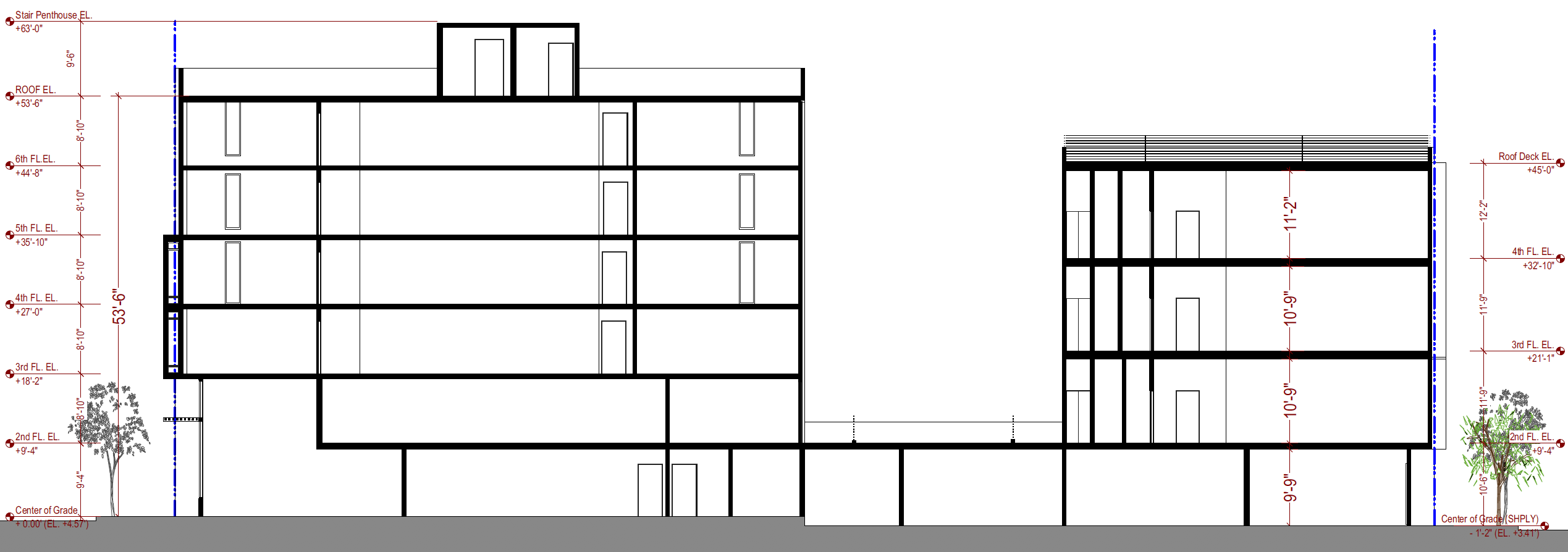
Just wondering what were your thoughts in setting this up using stories.
Left bulk - 8'10" typical flr to flr
Right bulk - 11'-9" typical flr to flr
1. How would the stories organization be set up.
2. When putting in furnitures and other miscellaneous items (such as railings), how do you ensure that it's at the right story? (from my knowledge, there is no "bottom bound" for these objects, would you just place the objects and offset them afterwards?)
Much obliged
-
10 hours ago, Alan Woodwell said:
Simplest way is to trace the contours with a 3D polygon, select each contour line and add the Z co-ordinate to each one, select all then AEC / terrain / create site model and you you should have a model.
HTH
I know how to create a site model so maybe "hard" is not the best word to use. Perhaps utterly time consuming is the better word.
The manual way you described is a 3-4 step process for each polygon. Each survey that I have received is almost always about 100+ polygons.
If we go through the manual process for each polygon, that would equate to 300-400 steps that one would have to take and that's assuming that the person going through the process makes 0 mistake throughout going the 100+ polygon.
Considering the site is something that all architects and landscape architects have to do. Vectorworks should have a better automated process instead of the current one that is in place. I'm just suggesting an integration of a better automated process that would make the process faster and simpler.
-
Problem:
The automated way of converting 2d polys to 3d source data always misses some polys
the other solution for this would be the manual way of adjusting.... however, the manual way of adjusting the 3d polys takes too much time for a large survey.
Solution:
If there was a "reverse direction" and a "skip line" option, that would be great...
the reverse direction option would aid in the direction of assigning the elevations to the polys
the skip line option would let you toggle through every polys that have yet to be assigned elevatiosn so that you can assign the right elevation to the right poly.
Thanks
-
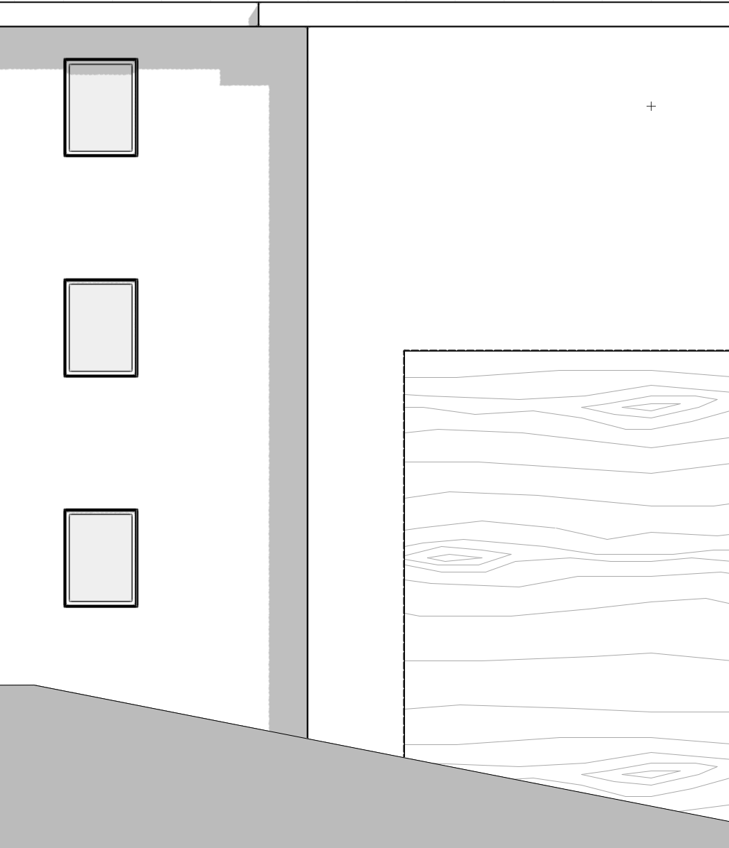
Hello my vectorworks brothers and sisters,
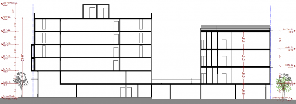
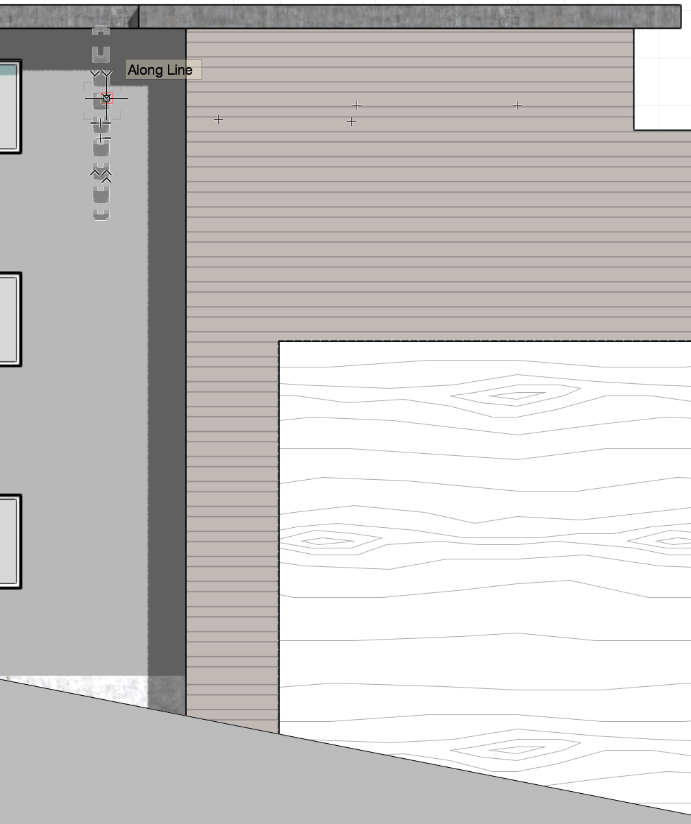
I have quite a problem with producing some 2-d drawings with a desired effect:
I want to produce a flat b/w elevation with shadows. Rendering with open GL with colors turned off seems to achieve the results. However, the textures (siding) which IS the color turned off as well (first picture). How do i produce a b/w elevation with the texture but with the colors turned off?
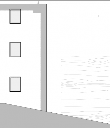
I tried adding bump to the texture and having texture turned on in my background renders setting but to no avail, nothing shows up.
I tried adding "hidden line" as a foreground render but that produced a lot of unwanted lines. Needless to say, it's not working the way i want.
If someone can help me with this situation, it'd be greatly appreciated.
Thanks

-
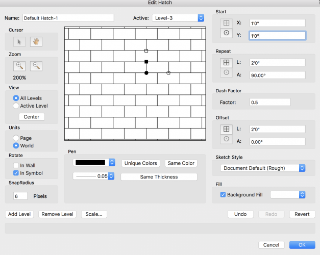
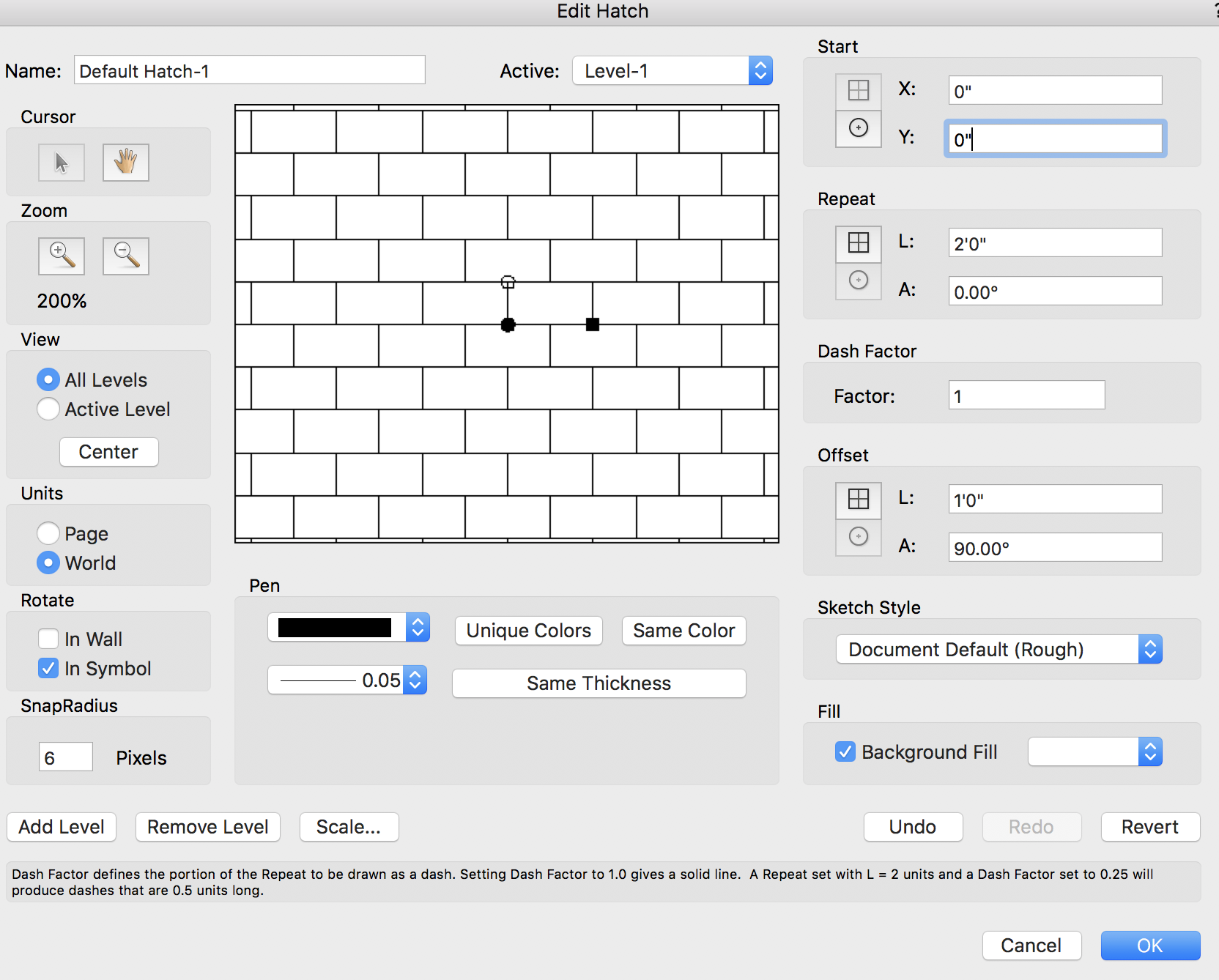
Andrew-
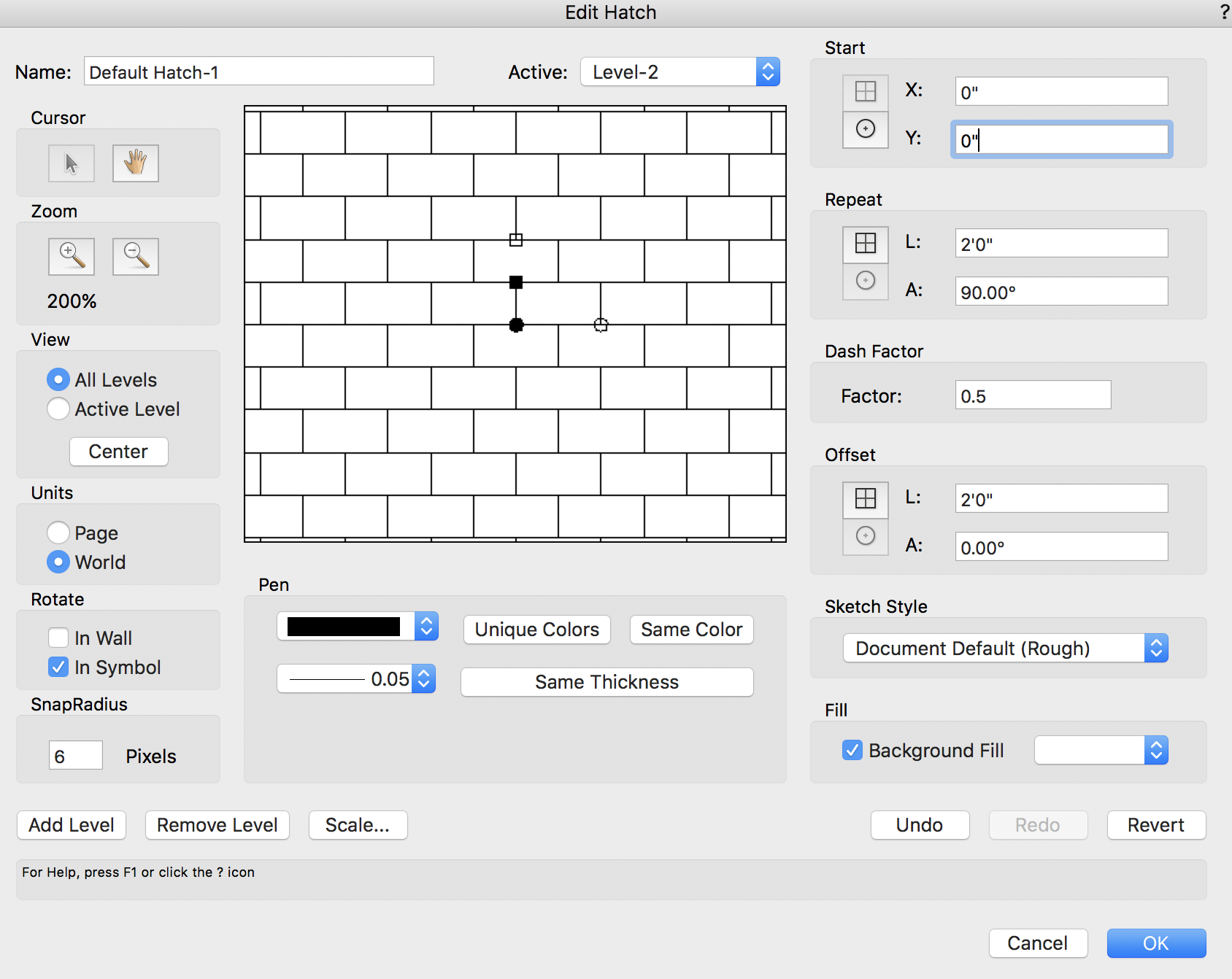
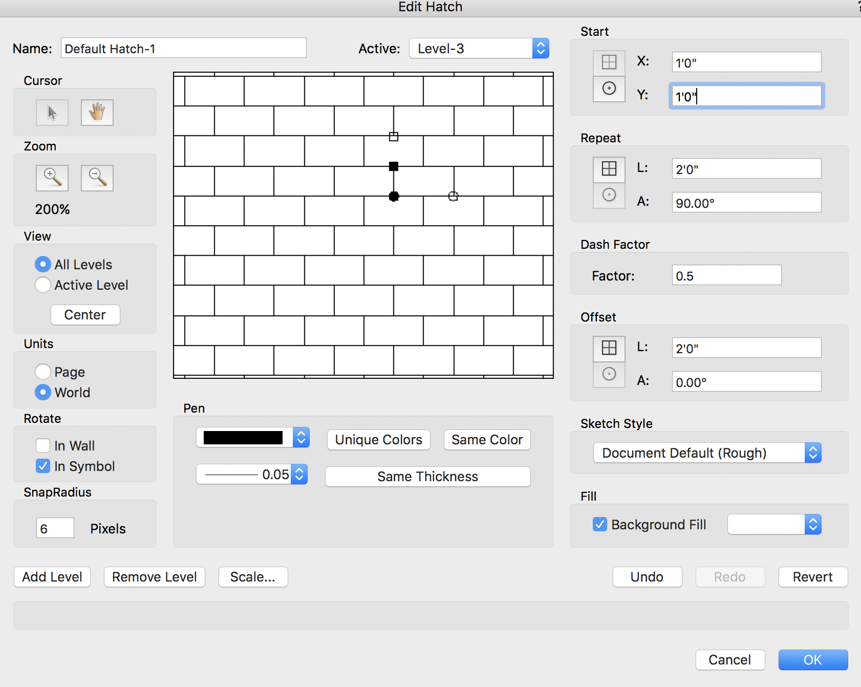
Don't know if you figured it out yet. But here's what i did to get a 12x24 running bond hatch.
If you follow input all the settings shown below, you should be able to get the correct hatch.

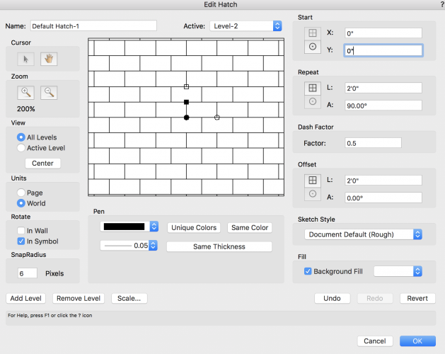
As for an explanation of how to do it, well... you just gotta figure it out yourself
Because that's the fun part of learning a program, isn't it?
")
-
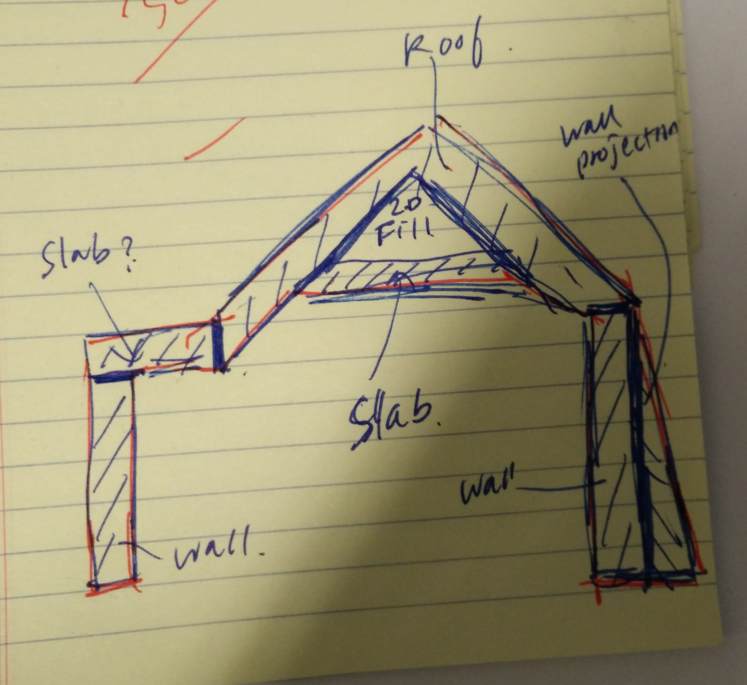
Hi Christiaan,
Here's how i would approach creating this:
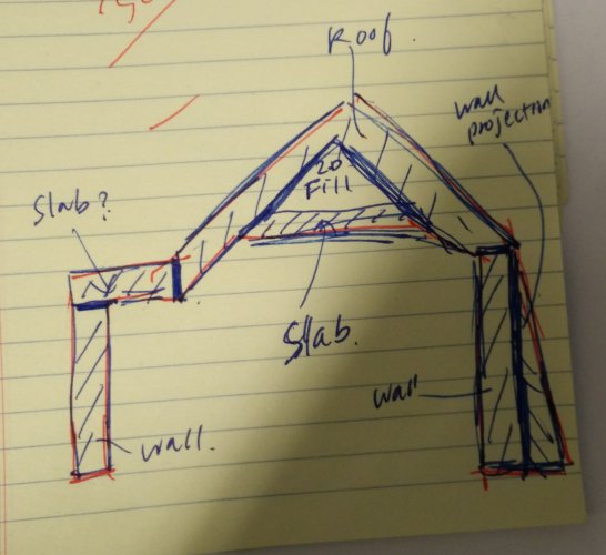
in this approach, the walls would be on the third floor layer
the roof and the slab would be on the roof layer.
In this approach, you would control how much of the right side wall projection (mansard) is visible through the cut plane option in the edit design layers panel.
Let me know if that makes sense
-
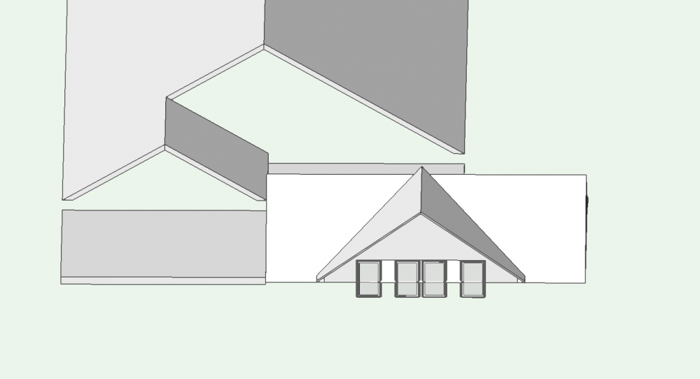
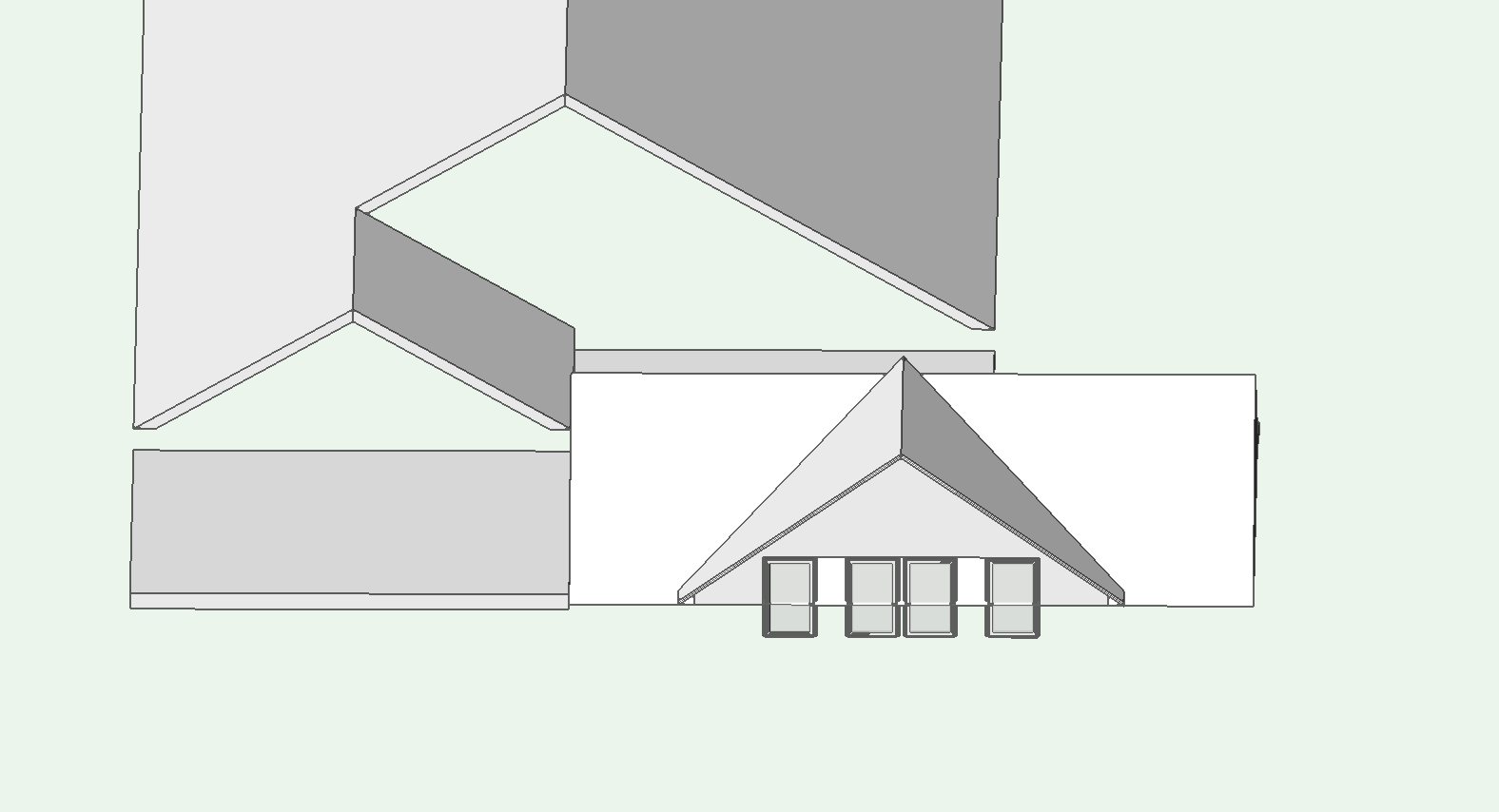
what i want to create
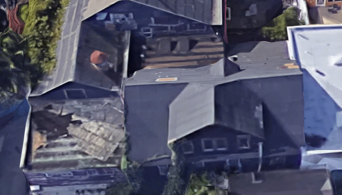
what is happening right now:
questions:
1. how do i adjust the bearing height of the dormer?
2. there is no offset of the dormer from the face of the building. however, if offset = 0, the dormer doesn't "cut" a hole into the gable.
Having a lot of problem with this.
Any help appreciated.
-
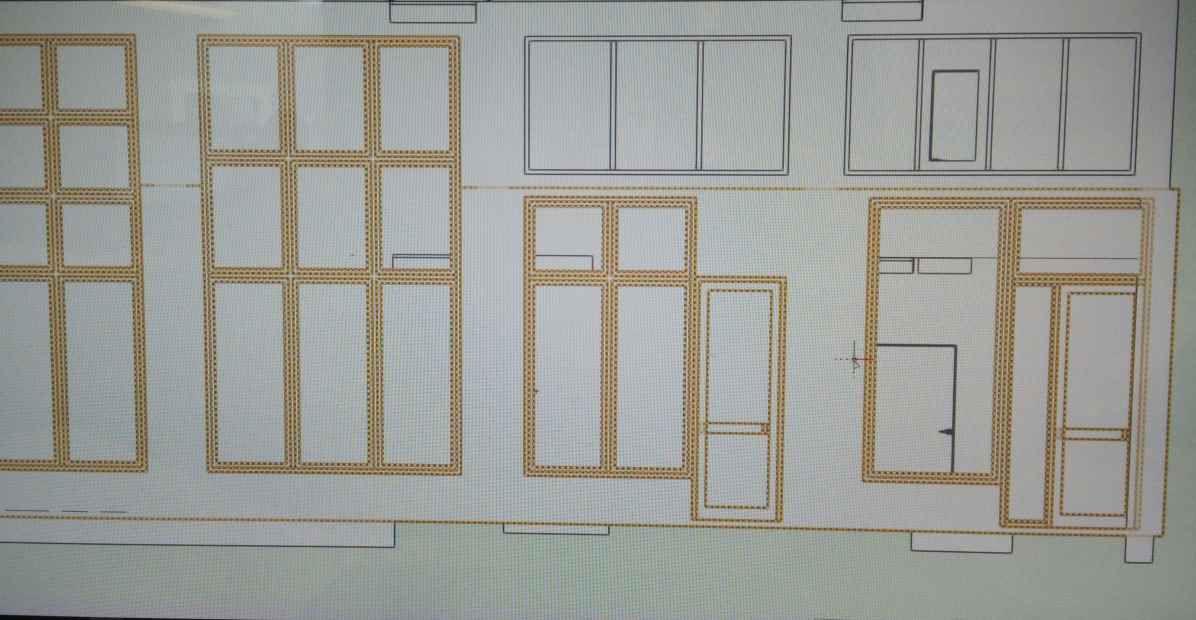
see attached.
want to make a window/door assembly (center) that matches the left configuration.
left configuration - 3x3 grid. right configuration would be the same but the lower right window would be replaced by a door
1. these are custom windows
2. the custom window doesn't allow us to knock out one pane
3. if i introduced multiple windows, the trim would make the spacing not match the left window configuration
4. having no trim is not an option
I've thought about this a lot but haven't come to a good solution.
the only solution i can think of is if i just physically model it the window then place it in a opening and then make the trim after all that.
this seems like a very tedious task so i'm just wondering if anybody could provide a simpler solution....
-
Any ideas on how to add ogee lugs on double hung windows and save it as a window style so that it could be reused?
-
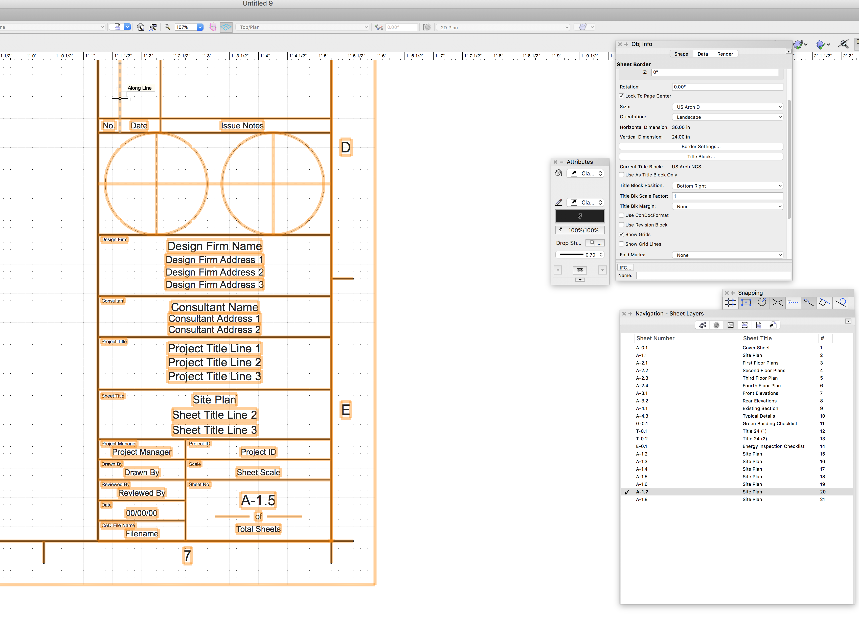
also, in my title block, my font styles do not display
-
using recordformat, when i duplicate a new sheet, the sheet number doesn't automatically change.
This is a small roadblock in terms of creating a lot of sheets. If there anyway to fix this problem (except resnapping sheet border into place?)
please see attached file.
-
Nevermind. Problem solved. Add # to the record format field.
-
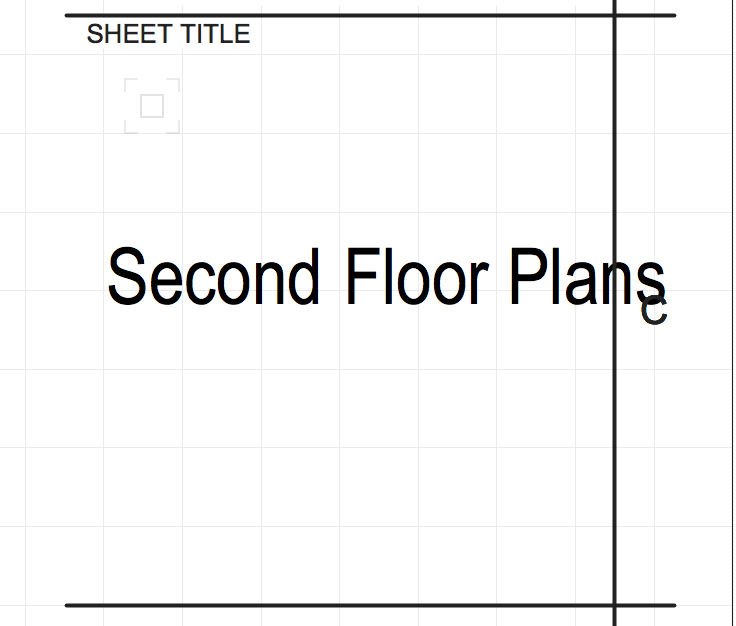
just wondering if anyone have a solution to a simple problem
by using record format, i'm relegated to using very short titles or else the title runs off the page (see attached).
In the navigation palette, the "edit sheet layer" doesn't necessarily give you a second line of title either.
THanks!
-
ah, was hoping that there would be a built in window function that i was missing.
-
just kidding, marionette is not a hump, it's a giant mountain.
trying to create a extrude rectangle with circular holes in them
here's what i came up with. (file attached)
1. it takes super long to run, my computer freezes.
2. can someone check this and provide me with tips and suggestions?
-
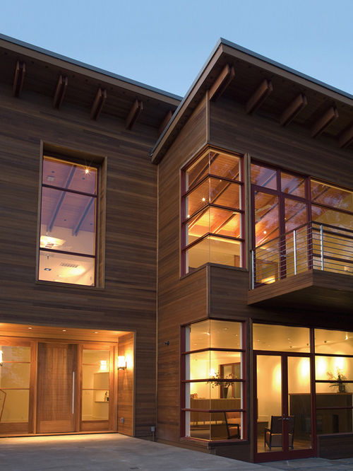
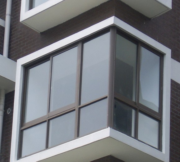
i'm consistently running into modeling houses with corner windows with custom sashes.
I've never figured out a way to do them effectively. The workaround is to have a thin wall and a tiny corner post.
However, are there any other suggestions?
(see attached) The first one is something that i can't do with my workaround solution, the second is doable but is lacking due to a visible corner post.
-
Hi All,
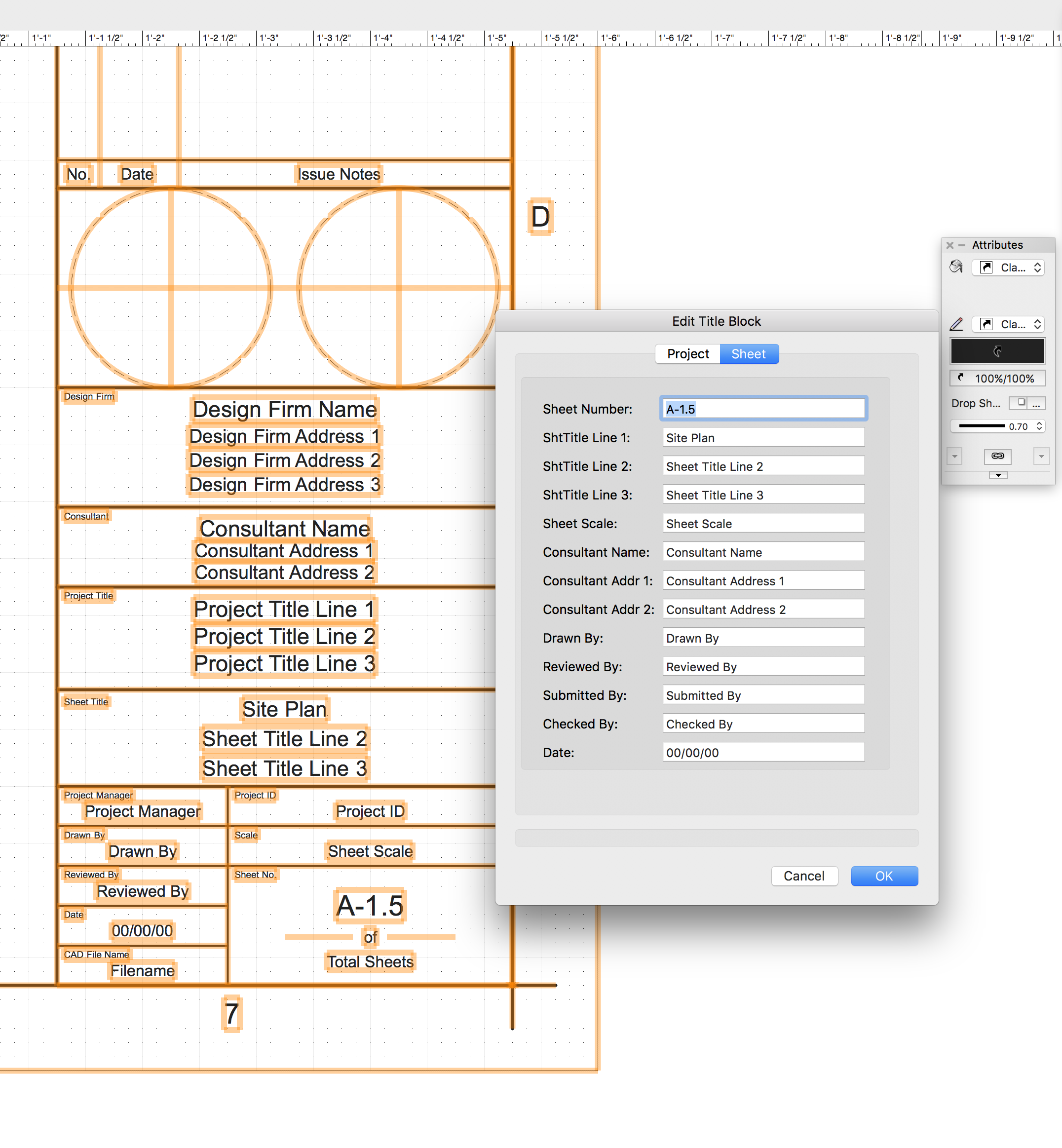
Just learning how to use record format by playing around with title blocks.
I'm using one of the standard title block that comes with VW.
For some reason, the sheet number is not updating as i duplicate my sheet layers. Though the "sheet number" changes under the navigation palette. The sheet number in my actual page (linked to the record format) does not change. (see attached)
I was wondering if there was a workaround to this problem.
-
Realized i didn't put this on the thread before. Just wanted a way to create corner windows with custom sash.
See below for a simplified version of what i want but can't do. Thanks!
-
I'm working on a building with windows in a parapet wall. However, I don't want to show the windows but merely the top of the parapet wall. I'm wondering what settings i can modify to help me with this. In revit terms, I want to modify the "view range" (see - https://knowledge.autodesk.com/support/revit-products/learn-explore/caas/CloudHelp/cloudhelp/2016/ENU/Revit-DocumentPresent/files/GUID-58711292-AB78-4C8F-BAA1-0855DDB518BF-htm.html)
-
I guess i want a more streamlined version of "guides". Right now, I feel like it's a bit too cumbersome and not intuitive. For programs like photoshop, it's a one step process and there's no "conversion" process involved, the guide stretches across the entire screen and you can lock/edit/move/turn off-on snap as necessary. Though VW does have some functionality with the current "guide" tool, it could definitely be improved.
-
 1
1
-
-
last request of the day and a strange one at that - thought it would be nice to join straight walls (see attachment). why? There are a lot of times when i draw a wall, split the wall for some design purpose, only to realize that i didn't want that. I don't think you can "compose" or "rejoin" straight walls even though we can do it with 1. linear dimension and chain dimensions 2. polygons and 2d shapes.
-
- Popular Post
I feel like there should be a way to change the units of elevation benchmark without changing the document units and without making each benchmark custom (which entails editing every benchmark). If my document is in feet and inches, there should be a way to change my "smart" elevations to decimal units.
-
6
-
I thought it would be awesome to include guides (like photoshop) and the ability to snap to these guides when we're moving drawings. I think one feature I missed when i transitioned from ACAD to VW was the lack of "Xlines" (construction lines) and by including guides, it would help with layout and drawing placement.
-
2
-

Need glazing to be clear and it shows up opaque
in Rendering
Posted
Also, make sure that your glass texture has the necessary attributes to be clear. You can find the texture and the means to adjust its settings in the resource manager.