Gadzooks
-
Posts
509 -
Joined
-
Last visited
Content Type
Profiles
Forums
Events
Articles
Marionette
Store
Everything posted by Gadzooks
-
@twk you're running two threads on this @Pat Stanford - Maybe combine? Ive posted to the other thread, but just to add to this for completion
-
I was struggling with this as well. The crux of the problem (certainly for me) is that VW classes the elements and provides an overall class for the complete wall panel and I couldn't see how to retrieve the correct class. Seems to me that VW would have done well to keep things simple and provide a 'component' build-up so the database enquiry could be based on Component(XXX) which works well with general walls. Still, I'm no expert so we work with what we have - and someone will no doubt come back with a reason why. The element (class) we want is 'Component-CW Glass' (check this out by turning that class view off) Based on that, Ive got a solution here which you might want to test for me. It reports what seem reasonable figures, but I haven't bothered to strip the walls down and add up the glazing to double check the results. You'll see it picks up all wall types (add a brick wall to the drawing), but doesn't 'find' CW's or glazing - you may want to modify the first column if you only want a CW solution - else use it in a larger report for all wall types. The File is 2018 and Metric. Come back at me if I've screwed up. CW Glazing Report.vwx
-
Ahh - 'he'. Does that confirm? Would be nice if he/she/it had a more personalised status rather than the Vectorworks 'V'. Just like you or I...

-
@murad intriguing. So is it the ...part that's crucial to your question? So that a choice from a previously defined group of hatches could be chosen? And, following the above, do we read 'hatch' (rather than texture) as being required within the wall (2D) or the wall have a hatch to sides when in 3D. I assume you specifying a pen weight possibly points to a Top/Plan solution. So there's quite a few options that should be confimed - maybe by you explaining the reason (fair play if it's straying into 'that's my business'). Else I'd go with @michaelk and steer you towards wall styles.
-
Hi @Haydenovative this has been covered before... I assume this will suit your needs. I think the only extra tip I might add would be that if your company has just bought 'the kit' and therefore you have limited sets of pieces, you might want to add a FLAG cell (of your own design) in the worksheet so the report will highlight there are too many pieces being used from the pieces you actually own. HTH
-
Gave it a 👍, but dont know why I should have to - There should be some sort of automated system that adds a few 👍 at the end of your posts @digitalcarbon
-
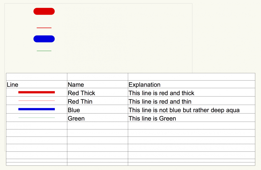
Just adding an adjustment for you @Mikedk64 Taking Pat's scenario - he suggested.. So the 'typical' lines will reside off drawing so to speak. If you make those lines as thick as you can - say 6.48mm (VW max) - you'll end up with a representation perhaps better suited to what you need. Using Pat's file I adjusted the larger Red and Blue to this (even!) larger size and the below is the effect you'll get. Try that for yourself initially. Just that change may provide what you want.
-
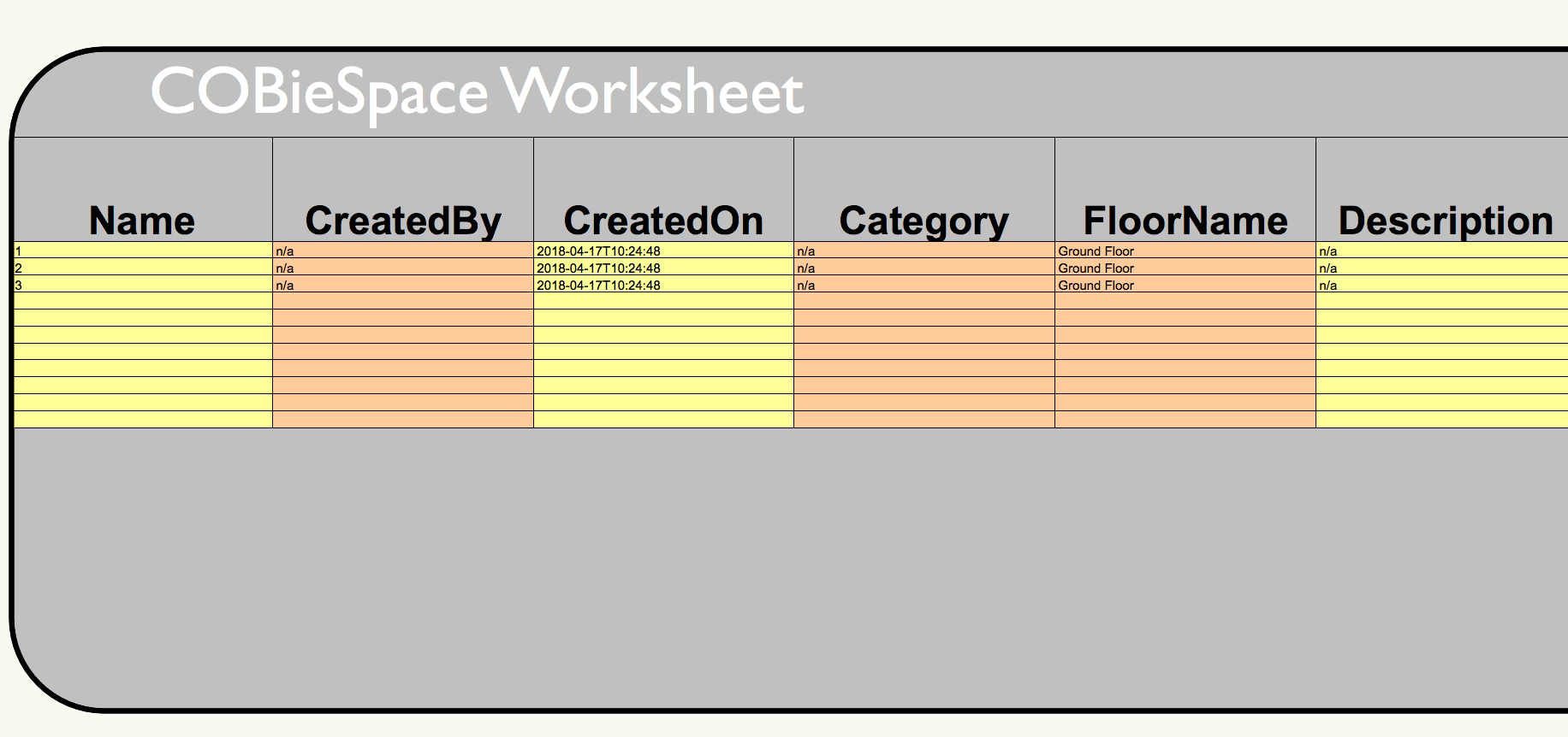
The 'image' can only be thought of as 'illustrative'. It's not a 'cut and paste' of the CAD you see when you place something on the design layer. There is a certain amount of 'tweaking' you can do. I'd recommend you start into some of the online help VW offers... http://app-help.vectorworks.net/2018/eng/index.htm#t=VW2018_Guide%2FWorksheets%2FInserting_Images_in_Worksheet_Cells.htm&rhsearch=image on worksheet&rhhlterm=image on worksheet&rhsyns= Also (although its is now old) the video link on that page will maybe help you understand what you can 'ask' of the Image Function. http://www.youtube.com/watch?v=_P1rfhKwD-Q Bearing in mind your OP was after a way to show colours in a Legend, I think it should be exactly what you need. Take a couple of minutes out to see what adjustments you need for your own (company) use. Hope that helps.
-
Haha @Pat Stanford - like a trout with a fly 🤗. Epic as usual Pat. @Mikedk64 stick with 'The Force'. Better than anything I'd have produced. And let us know when you've 'gone live' with it - it would be nice to know it's been a useful result for you..
-
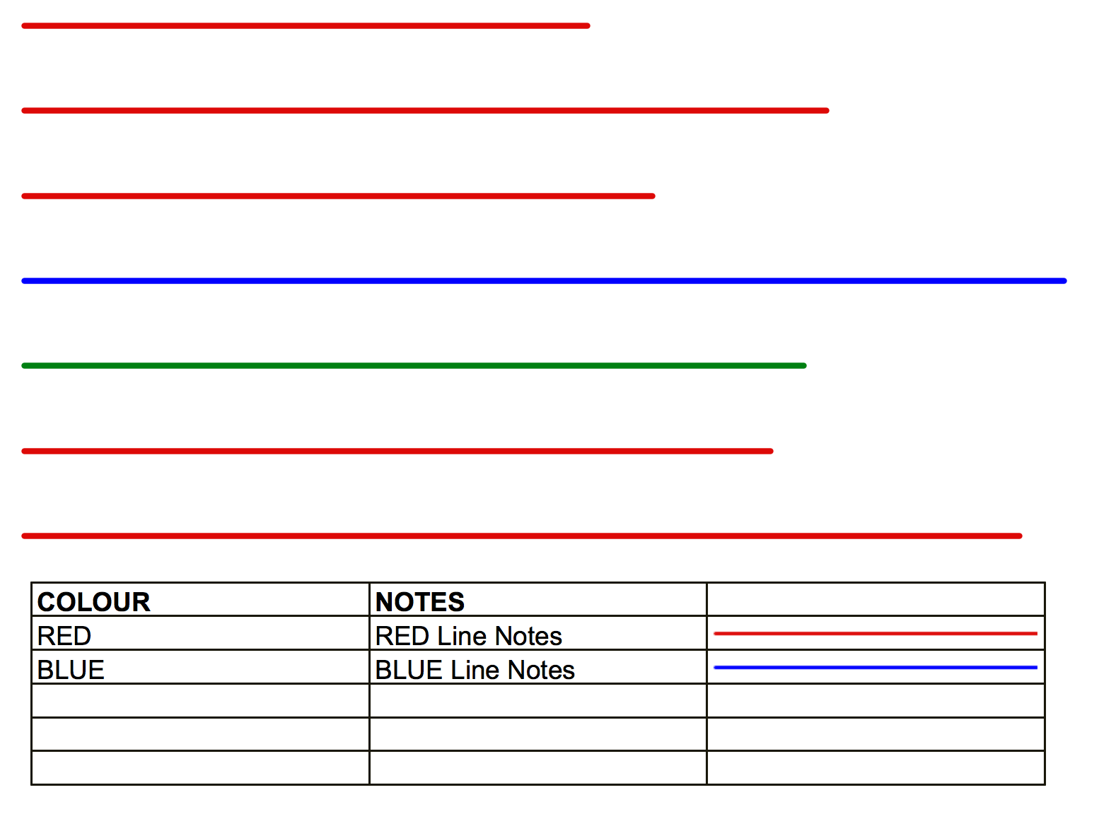
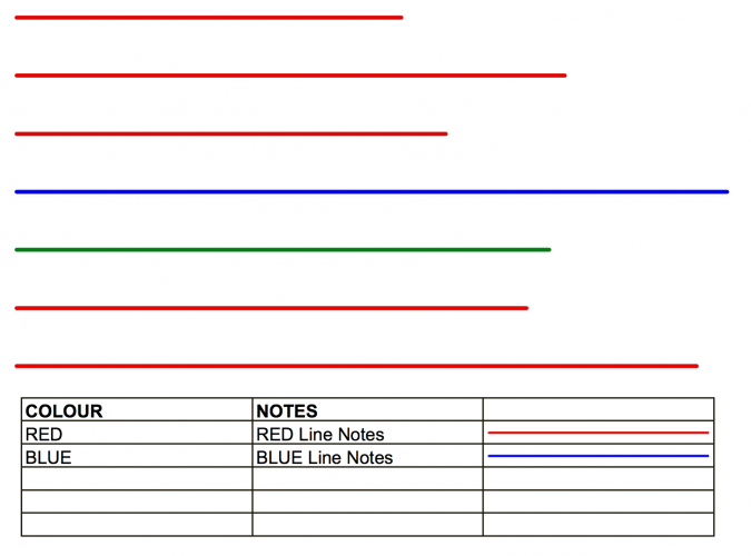
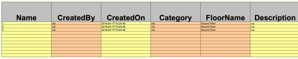
Hi @Mikedk64 There's prob a few ways to solve this for you. Just to throw this one in, how about... Create a worksheet that will be your 'Line Legend'. Set it up to add records for your (you say) about 20-30 coloured lines. Each has a (nominal) colour description added as a record and at the same time the (standard) notes that will be used as the 'explanation' to your clients. Records format will be set additionally to suite your requirements. Use Summarise (we only need an instance rather than a list), together with an Image (last column here) to give all you need. This will pick up instances of the records (line length etc not used). It will disregard those without a record (of course!) - so the green line isn't 'seen' on this LEGEND and the five reds are not counted individually. Being narrow, can be used in the Notes Margin of the drawing. Obviously needs some refinement (Headers and position of the columns, etc..) which you would want to do for your own company use. This offered as an 'idea' to get you started.
-

Skylights are not showing up on elevation in hidden line mode
Gadzooks replied to Hassan Raza's topic in Architecture
Guys - Just to move this one on hopefully with a bit more info for the boffins (couldn't let it rest, it was irritating me) Could someone try this for me and confirm please. If I place the vellux skylight symbol in a roof it works in hidden line. Take the skylight out and decompose the roof to leave roof faces. Now place the skylight back in place. Shows in OpenGL but not happy in hidden line. EDIT Just realised if you leave the velux in place and decompose, you decompose the skylight in the same action. This has the result of splitting the window from the roof penetration. For those wanting a fix for this, it then shows in hidden line!! The downside is you've lost control of the skylight position/penetration. -
Curtain Walls with different finish on both side
Gadzooks replied to Kohli's question in Troubleshooting
Looks like I'm probably not quite understanding whats to be achieved @Kori Your OP suggested the curtain wall option. I'd assumed this was to keep the structural steel seen (at least to one side). My earlier post (ok maybe some tweaking needed) essentially provided a metal surface on one side and filled the frame with insulation. which is what I understood you were after (and seemed a 'normal' application). If you wanted it the reverse, you'd change the colours to provide the steel panel 'look' one side and acoustic material covering the frame to the reverse side. The tweaking would have to come from you until you're happy with the results visually. This would obviously depend on the way you are presenting this wall in the project - not sure if its a 'major element' or just appears in the background of some views. If, on the other hand, you are after both sides being continuous panelled finish both covering the SFS (so now hidden in elevation and only seen in plan) - then we've kicked of incorrectly and you need to create the wall as a 3 component wall. 1 steel decorative panel covering the SFS (maybe 2mm thick), 2 structural element (SFS - thickness derived from the studs you are using), 3 acoustic material (thickness derived from calculation - maybe 40-50mm?). Have a play around and see where it takes you. -
Curtain Walls with different finish on both side
Gadzooks replied to Kohli's question in Troubleshooting
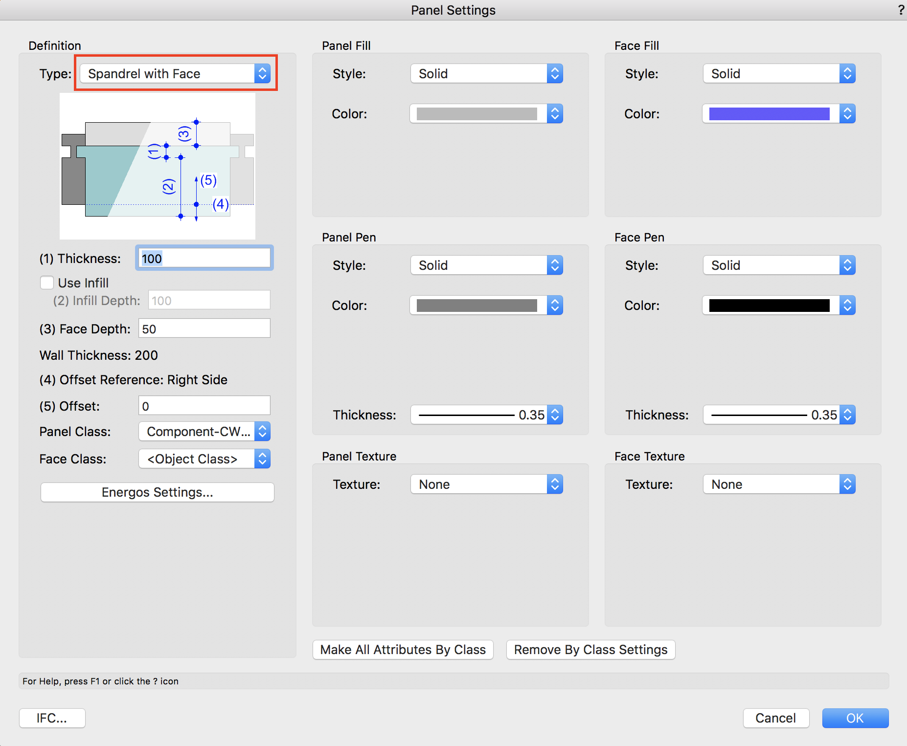
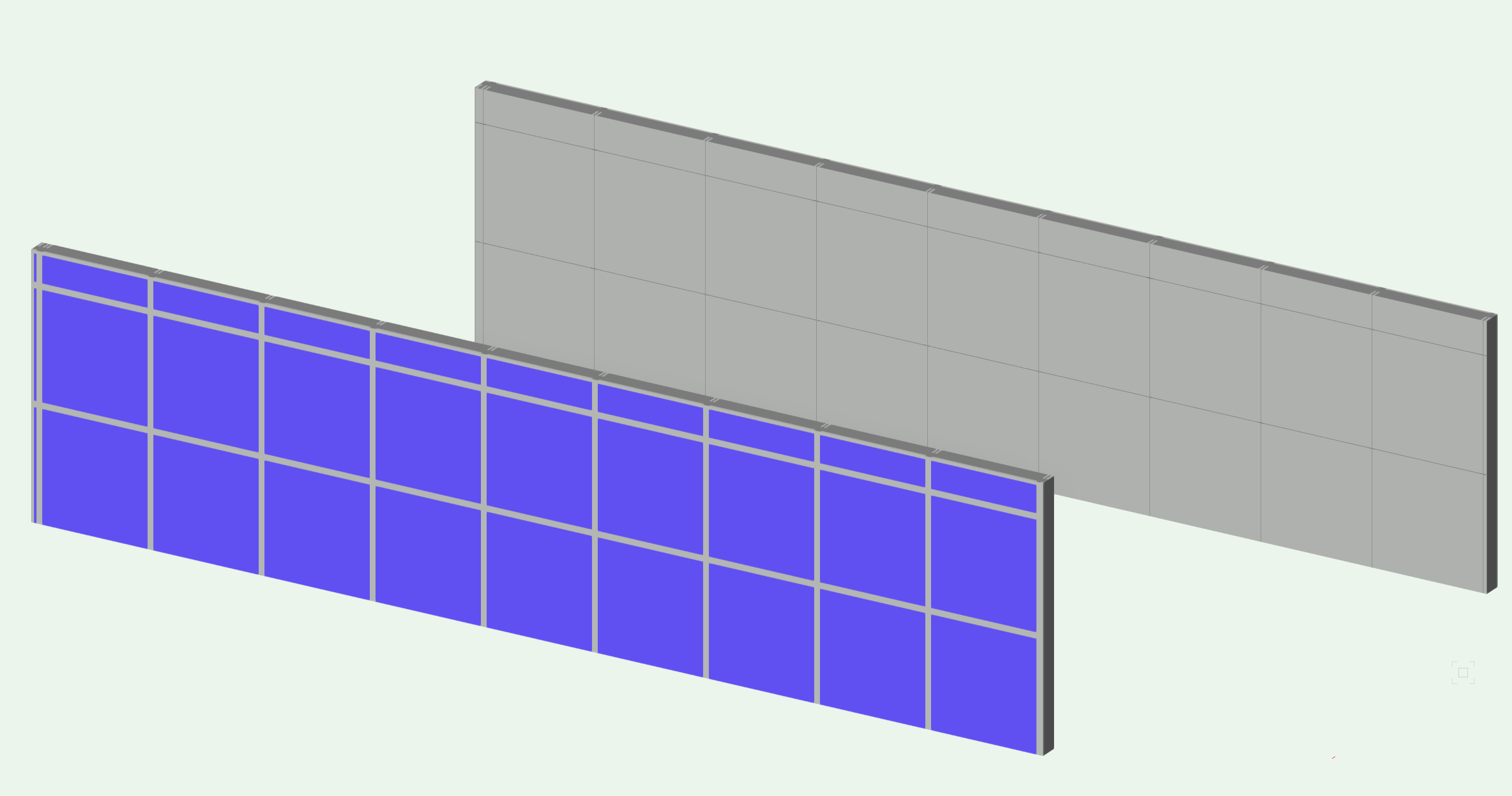
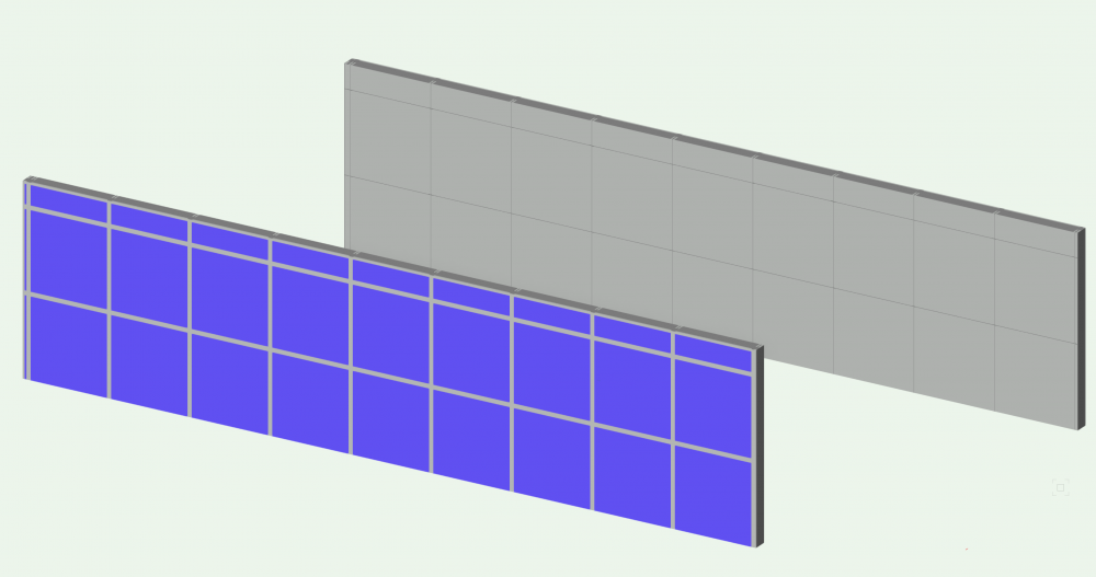
Hi @Kori It's a bit 'clumpy' (to adjust your choice of settings) but you can choose to use spandrel with face. Set different criteria for the panel and the face to suit your steel/acoustic set-up (you can see I've quickly set a grey for the steel and a blue for the acoustic material) and I think you'll be OK with the look you're trying to achieve. Texture is also available - I've not bothered and set it to None. Its just the 'trial and error' of setting the dims so that the panel has the correct appearance to the way it will be manufactured (getting the acoustic recess and the face of the steel looking good) that will take some time perhaps. Hope this helps - others may have a better way.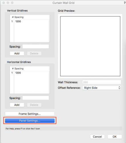

-
Yes - I do like this!
-
Skylights are not showing up on elevation in hidden line mode
Gadzooks replied to Hassan Raza's topic in Architecture
Sorry guys - seems this isn't the case. I think maybe the issue was fixed for OpenGL only. This was the earlier thread - for info Thanks for uploading the file BG. Yes - its has problems! BTW - Saving the file back to 2017 enables hidden line without problems. Definitely not a solution but an observation. -
Reports Records Database Worksheet Schedule
Gadzooks replied to Grethe Connerth's topic in Workflows
Nicely set-out @Boh So - I still think its worth pursueing the basics. No point in becoming expert at moon landings when you are only journeying to the end of the street (for the moment). Lets kick off with minimal info. What area of design are you in and what is a typical project for you. -
Reports Records Database Worksheet Schedule
Gadzooks replied to Grethe Connerth's topic in Workflows
Hi @Grethe Connerth - a lot of this is different terms for very similar things. I think it might help to get some specifics. Maybe outline what you want to produce and others could point you in the right direction without getting into word-blind territory. -
Hi Matt - Just interested to know why you chose to use the stair tool especially when the results started to give you grief. (In despair) I think I would have just created the few steps as an in-place extruded shape, especially as you didn't need the extras - handrail etc. Or was it "I'm going to fix this if it kills me" (which is fair comment for seasoned VW users ) Good fix from others.
-
Skylights are not showing up on elevation in hidden line mode
Gadzooks replied to Hassan Raza's topic in Architecture
Are they placed correctly? Placing skylights in roofs is, after all, like fixing a car with stone tools. There was an earlier bug - thats been fixed - where the skylight penetration showed but not the frame. What VW version/updates are you running? Other than that, an example file would be good to see the problem and help you. -
That's a good one @Pat Stanford I didn't consider that option. You'd just have to keep an eye on whether any recalc had resulted in an overflow of the crop shape.
-
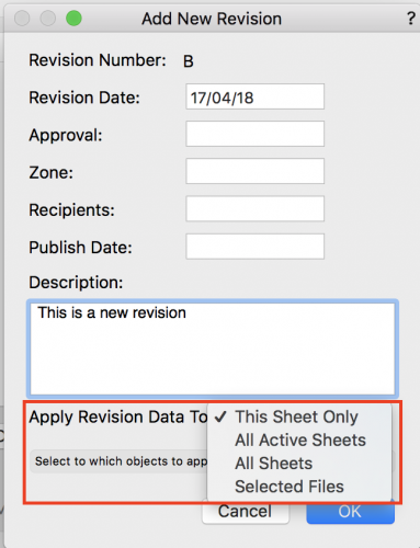
Hi @Mikedk64 Choose which sheets will carry the revision as you input the revision data. In the Apply Revision Data To: section ----------------------- Oh - Looks like you found it
-
Hi @Cris Dopher I've not done this - but good question. I'm not aware there is - within the worksheet 'environment'. I expect the boffins would say "why would you want to" - but we know its all about creativity. However (and not knowing what you want to achieve), if it's just a look you've previously had with other software and you'd like to match, you could take the sheet.. and place it on a suitable graphic of your own choice. Matching colours will help make it part of the sheet design. Do what you want behind the sheet - I've put the Title there. Not being connected (dynamically) to the sheet will mean you'll have to tweak it after recalculation (eg. if the sheet flows too far down and past the graphic). Works reasonably well if it has a 'buffer zone' below the sheet - as above Hope that helps. I don't use worksheets a huge amount - others will have a much better way.

-
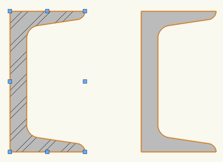
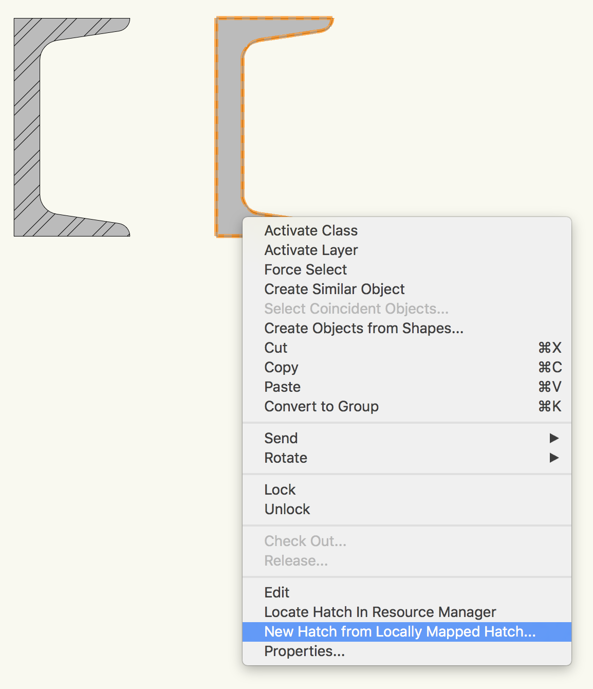
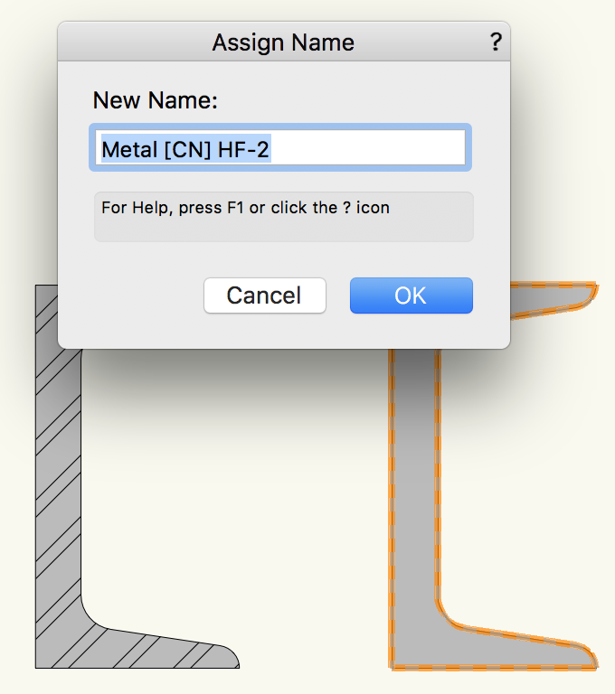
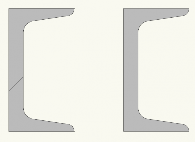
I agree. There's something very odd with this. BUG or WAI? Failsafe way to make the comparison (and to display the BUG/WAI) is to have (like you have shown above) a channel and a polyline derivative. If you highlight both and apply a texture they will (individually) show they have the texture in Attributes. For this 'experiment' I have modified the standard Metal (CN) HF hatch to have a grey background - otherwise at this scale there is too much white and it makes it look like the right hand (the channel) one hasn't received the hatch. Checking (individual) attributes confirms they have the texture. (but you can see that with the grey) Now highlight both again and make a local mapping of the texture. This is where it shows problems - only the polyline accepts the local mapping. Have a look at the Attributes though - it shows it has a local mapping. Something (WAI?) stops it displaying. Now right click on the channel (the one on the right remember!!) and choose as shown.. and then....... All is now 'fixed' - albeit the channel now has a 'true' hatch (not locally mapped) and is therefore happy to display it. I can't think this is correct, but it would be good to hear from the boffins if this is BUG or WAI. As a work around - you could apply the hatch to (say) any enclosing object drawn for the purpose and then locally map the hatch so it is an acceptable size. Now use that to create the 'new' texture version for structural shapes. But I agree - You shouldn't have to!!!! Hope this helps.


-
You'd think the Vectorworks fairy godmother would wave her wand for you. Would be nice to see a little honest appreciation of the people who used and evangelised (because we all did in those days) MiniCad over the competition in the early days. I too have that 'pedigree'. MiniCad was such a leap from ClarisCad (yes, I said it) and I wanted to share that with everybody I met that was still using drawing boards, scratchy paper and rotring pens - the development to today's offering is worlds away. Such is progress (thankfully !) Haha - I feel like Iike I should be adding "you youngsters don't know............" ( no, I'm not after a freebie! )
-
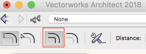
The option doesn't toggle. Its a straight choice. Choose the one that you do want. Vectorworks will hint the action if you hover over the choice. Its worth remembering this when getting used to the options displayed in all tools/commands/palettes etc.. HTH