JazzLX
-
Posts
98 -
Joined
-
Last visited
Content Type
Profiles
Forums
Events
Articles
Marionette
Store
Everything posted by JazzLX
-
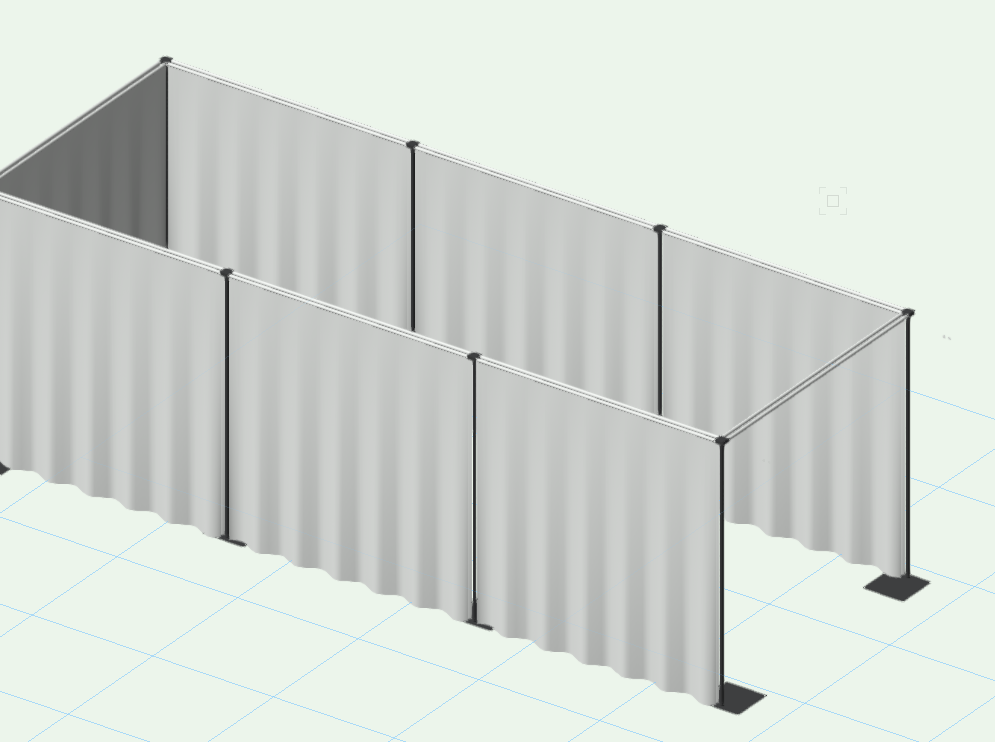
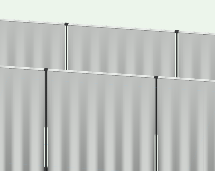
Hey hive mind. I can't seem to figure this out. I'm using the pipe and drape tool and I can't get the drapes to overlap at the upright. In the real world you would cover the uprights right? For example Wentex has an overlap, and there are sleeves for easirect poles etc. Is there a way to make this a thing? I've tried adjusting the overlap... no joy. Any advice? Thanks!
-
Superstar!!
-
Hey! Sorry for the lack of comms, I was finding it difficult to explain what was happening and the company I'm working with have VSS so I called the lovely UK support peeps up. Long story short we had geometry in file before we inputted the GIS data, which is what has made everything off, so we are starting a new file, setting up the GIS properly and then importing the drawing geometry back in, to the correct place. Thanks for the assistance and the wee video, it will be very useful! Jazz
-
Ah, Yeah, I'm good with that, got that bit sorted, sorry I don't think I've explained it very well... I've already done that... but the locations between GIS stake co-ordinates on the geo image to the land survey dwg are off. Let me get some pics together and show what I mean!
-
Ah, ok, I think I get it. The crop isn't autoupdating using the geolocate too, I need to relocate the origin and re-do the image. I'll give it a bash! Thanks guys!
-
Hey, Just wondering if you had a minute to explain what you meant in the earlier post about re drawing the geo image 🙂 Cheers!
-
No worries at all... I'm on my afternoon coffee!! 😄 Very much appreciated!
-
Hey, Ok... so after I move the image, I have to redraw a geoimage rectangle in order to see the updated view? Even though I've already done this previous to needing to geolocate? Sorry, still wrapping my head around this.... much more comfortable with truss and lights! Cheers!
-
Good afternoon everyone! I'm using the geolocate tool to align the GIS image to a drawing. Everything seems to work fine, it moves to the correct position, but when I change tools it snaps back, disregarding the changes... has anyone else had this issue? I can't seem to find any detainls on this in the manual... Cheers!
-

VW imageprops texture export issue or something more nefarious?
JazzLX replied to Jeff Prince's topic in Rendering
I don't think that VW has turned into Skynet just yet.... maybe in future updates? Perhaps, rather than it being the export that is screwing with the textures, it is the way it imports and sees the alpha, converting it to the black/white opacity map for use within software, therefore that's what it exports? I highly doubt that VW differentitates between user textures and shipped textures, so they must not be built in exactly the same way, probably something under the hood somewhere. It clearly isn't just the VW import into Twinmotion, as there are quite a few videos dealing with the issue in Twinmotion. Out of curiousity, have you tried using the direct export to datasmith function? Maybe it's fixed there...? -
VW imageprops texture export issue or something more nefarious?
JazzLX replied to Jeff Prince's topic in Rendering
Twinmotion doesn’t understand the opacity map, the black and white image used to create the transparency, in VW. I also believe that quite a few of the shaders that can be used when creating textures are specific to Renderworks and don’t export out, hence the reason some textures come out looking different. So if textures made by VW in the resource browser use these, they also won’t export out the shaders. It’s quite easily fixed in Twinmotion with no issues, this guys vid is quite good, though I’m sure I saw another one somewhere but can’t find it right now. I don’t think there is anything to fix. The two programs just work differently for transparency as far as I can tell…. -
VW imageprops texture export issue or something more nefarious?
JazzLX replied to Jeff Prince's topic in Rendering
Hey, This was a year ago, you've probably nailed this by now... but if not maybe this is helpful? https://twinmotionhelp.epicgames.com/s/question/0D52L00003bNsLISA0/hi-i-am-trying-to-apply-a-alpha-transparency-map-to-a-leaf-material-but-only-get-the-attached-result-i-have-checked-the-opacity-setting-in-twinmotion-but-still-dont-get-the-transparency-any-help-appreciated?language=en_US I'm trying to find a youtube video I saw on this..... Pretty sure it's a Twinmotion quirk rather than a VW quirk, although the direct export to datasmith seems to be pretty good on the projects I've been playing with. Apart from the glass... but that's probably me! -
@bgoff That's exactly what it was, it used WSGS84 as the default. Superstar, thank you! Also kicking myself as that's one of the first things, I now recall, in the Vectorworks University segment. My excuse, rather than being dumb, was that there was so much to take in! I'm sticking to it... 😄 The site is still under certain restrictions as to the sharing of images, so I was hoping that somebody would spitball something that worked before going to the dept heads to get clearance to post any further info - otherwise I would have, and usually do, post up more! Thanks guys! Stay safe!! @jeff prince
-
Hi all! I'm working on CAD for festival site and we are attempting to use georeferencing on the drawing. We have two known GPS locations for stakes. The trouble I'm having is that the GIS image is far bigger than the rest of the drawing geometry and I'm not sure why. The GIS stakes appear in the correct place relative to the GIS image, but for the life of me I can't figure out why the rest of the drawing isn't scaled correctly. I'm an entertainment user predominantly, so this is all kind of new to me. Any suggestions would be greatly appreciated! Many thanks!
-
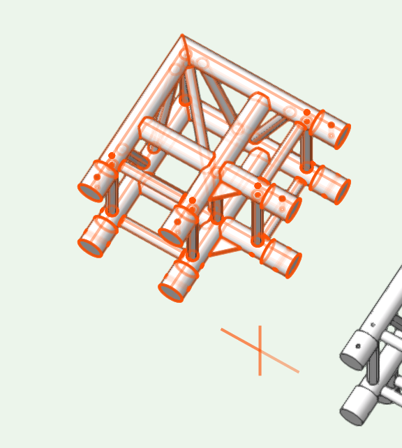
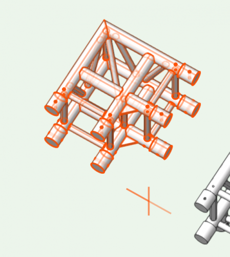
Ok, Having a little play with it. So I'm working on a right angle corner piece S36R-C003 and now I've shifted the geometry a little I'm kinda getting used to it. I'm guessing in the attached picture the orange crosses are the truss insertion points for the two connections, so I now need to rotate the 3D geometry for the correct faces to match this and then it will be correct? How does this work for especially complex pieces such as the Prolyte S36R C012 and C013 where there is a left and right version of the truss pieces? I'm trying to get my head around initial geometry orientation.... Thanks again! Jazz
-
Hey! Perfect, I'll give that a bash! And do it in the right order for all the other symbols! Thanks!
-
Hi Justin, THanks for replying so quickly! That's most likely the issue then. Should the insertion point be set before running the convert to truss tool? Thanks, Jazz
-
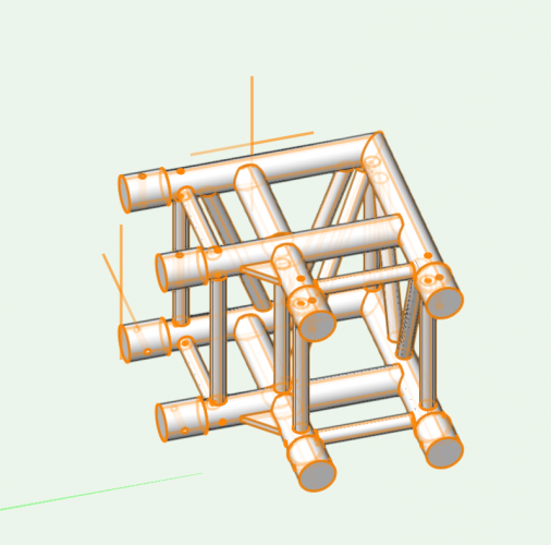
Reaching out to the hive mind to see if anyone has experience with creating custom truss symbols using the 'convert to truss' tool. There are a few Prolyte S36R objects that I can't find in the library, the corner blocks and such like, so I decided, in my wisdom, to use the DWG symbols available on Prolytes website and make my own. All seemed to be going well using the 'convert to truss' tool, entering all the info I could find etc. until I jumped back out and tried to attach the truss section to each other and it goes mental berky. The insertion/connection point seems to be way off, as shown in the picture, and for the life of me I can't figure out how to fix this issue. Has anyone experienced this and found a workaround, or just generally more intelligent than me? Any help would be greatly appreciated! Jazz
-
Hi Juan, Thanks for the info, the file was made for the company, they don't have access to navisworks and neither do I unfortunately. I'll keep digging and see if there is another version somewhere! Thanks, Jazz
-
Hi all, I'm working on a project and I've been sent a navisworks .nwd file. Is there a way of importing this directly into VW20? I'm not too familiar with all this so any help would be greatly appreciated! Thanks, Jazz
-
Morning/afternoon/evening world! Wondering if anyone can help me, I'm trying to apply textures to doors in walls. I'm going to the render tab in object info and chaging it to an appropriate texture but it doesn't seem to be applying it in the opengl of the model. Any ideas on what I'm doing wrong...... again..... Thanks, Jazz
-
@Aspect_Design Yeah, I'm digging the movements, going to make everything so much easier! Looking forward to getting used to it!! I'm really hoping the buttons wil make my life so much easier, particularly with the toolsets and also the radial menu is so cool! @herbieherb Yeah, I love how smooth it is between all the programs, so quick! It does mean you have to be aware of what you have open so you don't get confused! it's the shortcut configuration area that is confusing me, the Vectoworks folder is there but it isn't populated with many shortcuts that I can see, particularly compared to what I've seen when researching online. I cam across a post on a forum where a user had mentioned that they had the 'default vectorworks' profile loaded and when they loaded the 'VW 2020' profile it was far better. Just no clue what this was about!
-
Hello everyone! Wondering if anyone can help me, I'm a bit confused. Not an unusual occurence to be fair! I received my lovely spacemouse and cadmouse wireless kit today to use with Vectorworks 2020 and I'm just trying to get my head around the customisation. I've looked around on various websites to find out how to customise the buttons and so forth, but in the customisation fields I can only see some basic commands, whereas on many of the videos there appear to be a huge list of commands to choose from. Are these ones people have done themselves or am I missing something? I'm on the latest drivers... :o( I'm using this on a windows laptop. Any help would be greatly appreciated! Jazz
-
Wow, would have thought VW would have made the wheelchair library files on general release!
-
Hey, I did a bit of trial and error on it, got it to work in essence! Thanks for the assist! Jazz