
mgries
-
Posts
135 -
Joined
-
Last visited
Content Type
Profiles
Forums
Events
Articles
Marionette
Store
Everything posted by mgries
-
Hey thanks! will do. I ran out of time today unforturnately...I'll send tomorrow.
-
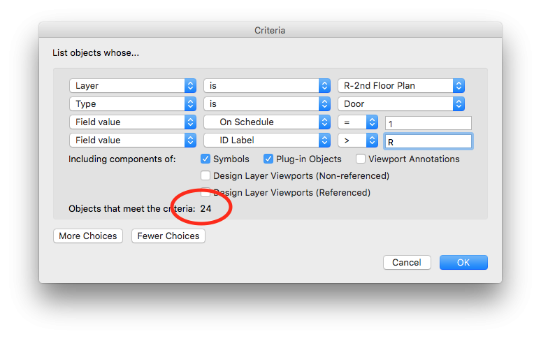
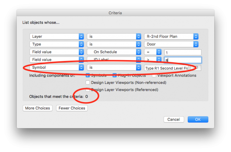
@PatStanfordand @Alan Woodwell, I'm having a related problem maybe you can help me with. For Unit based design, we are also using symbols. Our Residential Unit symbols only encompass interior walls. All the exterior and shell design lives independently on the DL. Our solution to the whole Unit scheduling issue is to use door types, not individual door I.D.'s. Door Types work well for tracking the interior residential doors on multi-family projects. This way, there's no issue having the same Door I.D. displaying across multiple Units. No issues there. I am having a frustrating technical issue however. If I want to look at which specific door types occur per a particular Unit type, I should be able to isolate the search based on the Unit symbol. This isn't working however. Whenever I add a symbol name to the search criteria, I get 0 doors, no matter what. Check out the screen shots. Any idea what's going on here? Thanks, Matt
-
 Hello Marionette aficionados... I would absolutely love a tool for drafting all Site related surfaces/areas including Existing, Demolition and New conditions. Basically it would take a polygon and turn it into something similar to a space object, but with a lot fewer functions. full disclosure: I do not know marionette Preface... Site Plans seem simple, but to fully coordinate all the information that gets put on the Site Plan is pretty intense. Our building department makes us fill out very detailed worksheets. They want to know the area of everything. Getting this info correct is the sort of thing that slows you down to a crawl when you're getting ready for submittals. Description of Tool... One of the biggest benefits of this tool, would be that you could make all of your site surfaces on a single class, let's say "A-SITE-AREA", and allow a lot of graphic changes and record keeping to be bundled into the tool (similar to a space object). But it doesn't need to be nearly as complex as a space object. Space objects are a bit heavy and clunky, and I think drawing a siteplan using spaces would create an undesirable workflow. The OIP for this marionette would need to control the following parameters: "Surface Type": This list would be pretty long, and would cover all of the site classes we currently use when drafting a site plan. It needs to satisfy the basic Architectural, Landscape and Civil design elements. You would still need all these classes in the document, it's just that you wouldn't have to constantly be switching to different site classes as you drafted. Instead, the tool would allow you to link each surface category to a specific class, so that the pen and fill properties belonging to each category could still be independently controlled by separate classes. It would be like how door and window component graphics work. You can link each one to its own component class, or you could choose the object class to keep things simple. "Existing", "Demolition" or "New" ("New" would be the default): Including this function means that each surface category would potentially need 3 separate options for class assignment, one for Existing, one for Demolition, and one for New. Having this single feature hardwired into the tool would save a ton of drafting work. It would also make Site Data Tabulations a lot easier. "Pedestrian" or "Vehicular" (for hardscape surfaces): This wouldn't effect class assignments, but would be needed for Site Data worksheets. Yes, we're asked to provide this information in some jurisdictions. "Permeable" or "Impervious": This also wouldn't effect class assignments, but would be needed for Site Data worksheets. Turn Line Work On/Off: Turn Fill On/Off: Duplicate Line Work: An important feature would be the ability to push a button and get the polygon line work redrawn, removing it from the marionette object, and put onto the appropriate class associated with the surface element it represents. You would want to be able to select multiple surface objects all at once, and then run this command, putting the resultant line work into a group, so it could be easily selected and moved to a different layer. Duplicate Fill: The same goes for the fill Add Label Display Name/Title Display Area Is all of this achievable with marionette? Thanks! Matt Regarding Landmark... I know that Landmark has a Hardscape and Landscape tool that is similar to what I've outlined. If I had Landmark, I'd probably be using these tools. I recently posted to the Site Design section about this to see if I was overlooking something in my version (see link directly below). But there's nothing in Fundamentals or Architecture that does any of this for us. So now I'm turning to all you marionette aficionados... I'm hoping we can make something even better using your skills!
 -
Hi Tom, Was browsing through this topic, and this caught my eye. When you say "style by record" are you referring to a viewport's "data visualization" feature, or something I don't know about which would be more directly linked to a drawing object? thanks, Matt
-
Dom, WOW!!! I love this so much! It's definitely one of the best, oddest and geekiest things I've seen in a while. Seriously creative too! A belated Merry Christmas!... and Happy 2018!!!
-
Pat, First of all...Happy 2018! So I tried calling this up in a worksheet, and it didn't work for me. It's a VW2016 file though. Should this black magic work on 2016? Matt
-
@rowbear97 Ha! In all seriousness, if I were to hire a landscape architect who is using Landmark, I would think that would be all the more reason to have some of these tools available with which to coordinate. As an Architect, it's important to get in the ballpark with these elements in order to move forward with early design drawings.
-
I'm just realizing that my VW Architect doesn't contain some of the basic Site Planning Tools I would expect to find, even for primarily Architectural uses. Is there really no Landscape Area Tool for me to use? Does Vectorworks offer any way for Architects to designate general Site Plan areas (such as pervious and impervious surfaces) using a BIM feature? We need this too. Thanks, Matt
-
Wall With Interchangable Assemblies
mgries replied to Tom Klaber's question in Wishlist - Feature and Content Requests
@Tom Klaber, I see this is a bit of an old post, but I really appreciate the thought you put into this! There would need to be a bridge between finishes assigned to walls and those assigned to spaces, so the information could be linked or transferred, rather than only belonged to one or the other. Also, there's the issue of tracking rated assemblies, as you mention, so a bit more thought is needed here, but I think what you propose offers a lot of flexibility to deal with all assemblies, whether rated or not. The tagging of a rated assembly would need to belong to the combined wall assembly (structural + finish). So if you changed the finish assembly, you would cancel out the rating data. Rated assemblies, irregardless of software capabilities, is always going to be a complex issue in terms of documentation. It conflicts with documenting walls the way you show above (finish assemblies and structural assemblies kept separate). When rating isn't an issue, this method works great though! Regarding wall ratings: Another wishlist item, and I know this has been talked about on the forum already, would be a simple way to control the graphical representation of rated walls, floors, and roofs, unrelated to any assembly graphics. Has VW2018 addressed this at all? If not, we need this feature! This should be a simple check box ("show wall rating"). It's essential from schematic design through to construction documents to be able to see a (class dependent) annotative graphic attribute running down the center of (or maybe sandwiching) any rated assembly. Even before specific wall assemblies are dialed in, and well before that amount explodes to 30 different types, we still know the general TYPE of wall assembly - as far as required rating is concerned - and need to track this information and represent it in our drawings. Building this into the wall tool as an annotative component would greatly help improve the efficiency of documentation, as well as overall quality control. Matt -
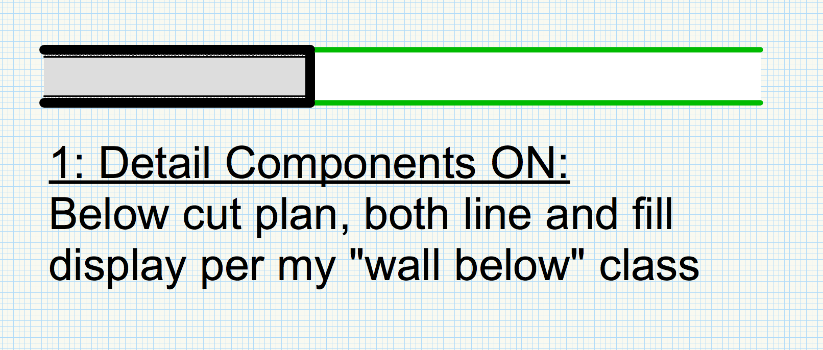
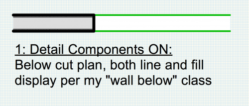
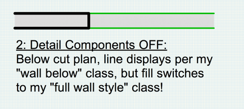
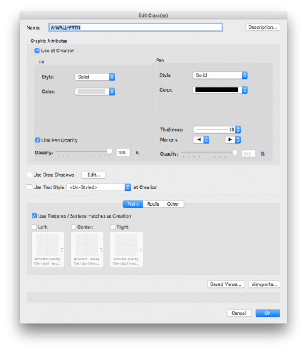
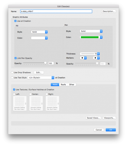
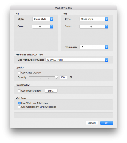
This tool was so close to being VERY useful! But the fact it only relates to wall components is rather self defeating. We have viewports for simplified presentations where we like to turn off the wall components (i.e.- for schematic design). Partial height walls below the cut plane all of a sudden display like they're being cut (per main wall class assignment). I would expect the main wall class to follow the same override algorithm as the component wall classes. This seems like an odd oversight. I hope we don't have to wait to long for this to be fixed! CORRECTION! I must have been doing something wrong. I can now get the class display override to work when components are turned off. I'm not sure what was going on the first time around... I guess the only issue is when the wall is above the cut plane. CORRECTION TO CORRECTION...IS THIS A BUG?? This tool definitely is not working correctly. Can someone please tell me if this is a bug? Aside from unstyled walls not obeying cut plane algorithm (which seems to be per design), my styled walls are getting tripped up as well. Here's the set up: My partition walls are set to A-WALL-PRTN class, which is set to 18mil with a grey fill. When the wall goes below the cut plane, I set the display to my partial height wall class A-WALL-PRHT, which is 10mil with a white fill. I should probably just name it A-WALL-BELW so that the names aren't so similar. Anyway, I've included screenshots of these settings. Here's the glitch: When I have my wall detail components turned on, both the line and fill display correctly below cut plane. But, when I turn off wall components, the line displays per the partial height class, but the fill reverts to the full height partition wall class! What's going on here?! Please help if you can... mcg
-
@JimW, I thought new marker types got written to some file hidden on my hard drive. When I add a new marker type, and then open up a new file from scratch, the new marker type is still there on the marker list, so it doesn't seems to be independent of the document that was open when it got created. What is the best way to share a custom marker list with a whole office besides going around to each machine a re-editing the list? Thanks, Matt
-
Better "Incadesent Fixture" Tool
mgries replied to Tom Klaber's question in Wishlist - Feature and Content Requests
I noticed that VW2018 has included incandescent fixture as one of the new and exciting "style" based plug-ins. I'm not running 18 yet. Can anyone report on what added benefits the style based version brings to the table? -
I agree that a complete overhaul of the callout and notes legend tool should be a priority for the next release. It's one of the more limited and least user-friendly aspects of the software. Considering how essentially notes are for documentation, this is really an enormous oversight. If a complete overhaul is not in the works, improving the current tool in the following ways would definitely help a lot: allow categorical tags to be applied to notes. For example, I would tag many notes with their appropriate CSI category. provide search bar in the notes manager, allowing notes to be filtered by text or tag allow a single keynote legend to be placed on multiple sheets allow a single note to be applied to multiple legends. allow worksheets to be created from notes database. Thanks, mg
-
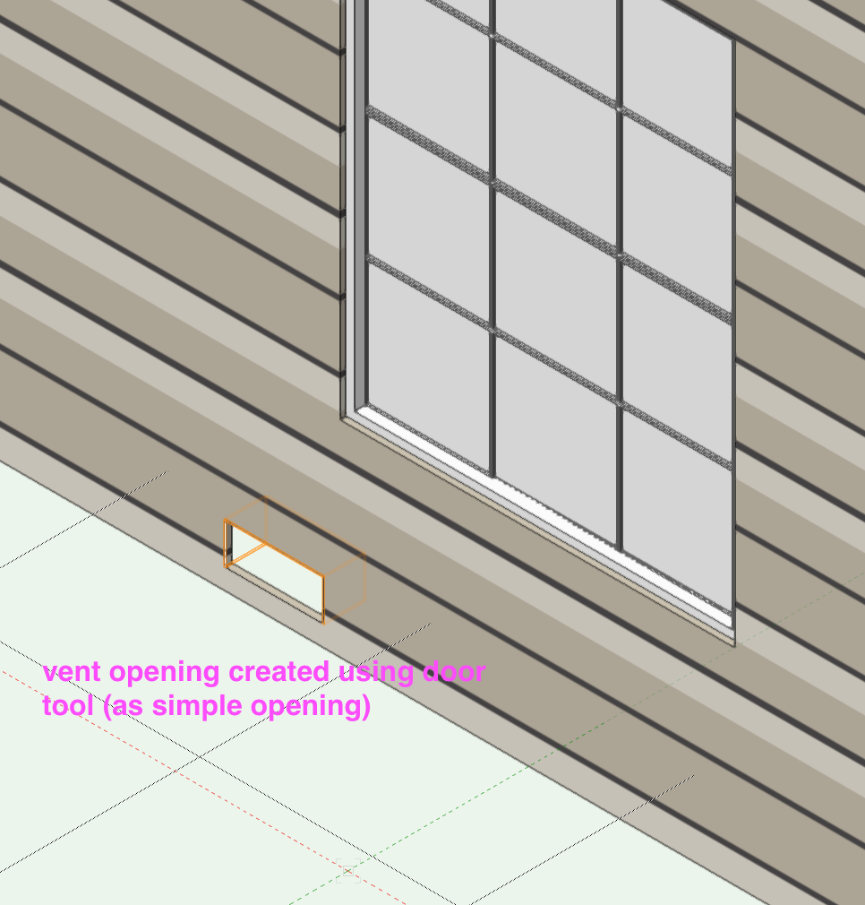
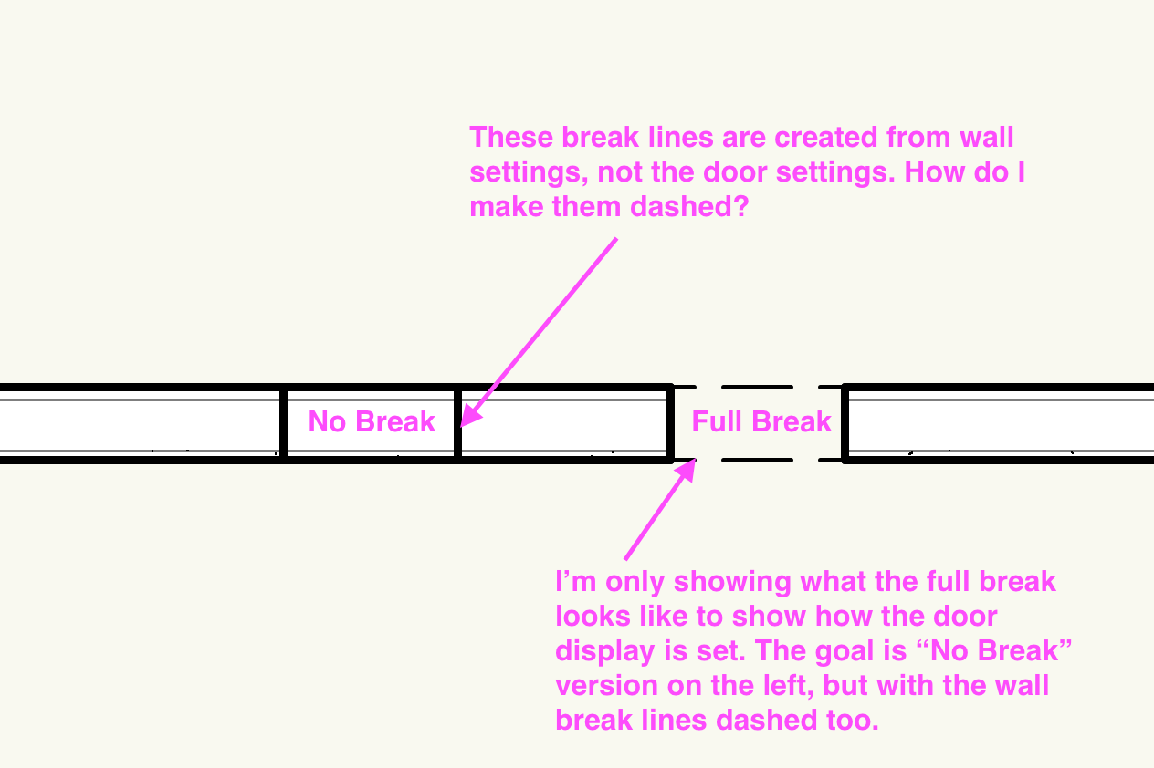
Related to this, I have a wall opening display question I would love answered: I have used the door tool to create vent openings in the stem wall below (vent openings to crawl space). In plan, I would like to show my wall break lines to be dashed, but I can't get this to work. I am displaying opening set to "no break", which gets me half way there. For the life of me, I can't figure out how to control the display of the perpendicular break lines. See screenshots... I hope someone can help me...this is driving me crazy!
-
I suggest a generic "Wall Opening" tool, separate from Door or Window tool, to control all of these issues. It could contain all the necessary options for capping, without having to integrate it with the display settings for actual AEC objects. A cool feature to add on top of this would be to designate the opening for the purposes of ventilation, potentially allowing application of vent coverings to be built into the tool.
-
Hi mk, I'm in need of this exact script! I use a space label and calculate the occupant load using the formula field, but I'm stuck displaying the result using the decimal precision set for the entire document. Please share if you can find this! Thanks, Matt
-
A way to do this without the script is to use the Formula Field under "Additional Data". I fill this out to read "=#Gross Area#/#Additional Info 01#", then the space label can call up Occupant Load directly from the Formula field. There's a rounding issue of course. Does anyone know how I'd write this formula to take care of rounding? Thanks, Matt
-
I'm coming in late to this thread, but.... What about "advanced" project info. related to code analysis (Occupancies, Construction Type, Exiting components, etc.)? It would be helpful to store these types of code related parameters in order to greater leverage space tabulation worksheets. Currently, we use worksheets in spreadsheet mode, and add lots of nested formulas to help with tracking code analysis. But it would be nice to tie this sort of worksheet into project info. from a database. Has anyone given thought about storing and utilizing this level of project info? The only thing I can think of to use at this point would be a custom record. But I can imagine more of a pre-formatted questionnaire type tool instead, ideally with pull-down options, and yes/no check boxes. Thanks, Matt
-
Create Drawing Title to show VP name and scale
mgries replied to Josh NZ's topic in General Discussion
@Andy Broomell, beautiful! This is a good work-around, but I still vote for the added feature of being able to save drawing label styles, and then being able to select style on the fly while creating a new viewport (or while simply adding a drawing label into an existing viewport). thanks! -
Create Drawing Title to show VP name and scale
mgries replied to Josh NZ's topic in General Discussion
Does anyone know how to create different graphical presets for different types of drawing labels in the same file? As far as I know, you only get one drawing label default setting per file (aka: the last one used before the file was saved). But we have a few different ways of graphically representing our drawing labels. For example, our Detail drawing label is formatted to fit snug in a grid box, whereas our Plan drawing labels are longer and have a few other tweaks to the graphical display. I'm finding it a bit tedious to have to reformat my drawing labels continually throughout a project. I'm hoping there's a way to store a preset for a few basic types. Any suggestions? Thanks, Matt -
Using a Wacom Tablet (Intuos Small) with Vectorworks 2016
mgries replied to k f's question in Troubleshooting
I have a general question regarding use of Wacom Intuos (Pro or other) Tablets: I'm interested in incorporating a tablet into my workflow, but I'm not sure how it's being leveraged with VW. Is it just used as a fancy mouse that provides pen control and touch-pad gestures (as well as handy preset shortcut buttons)? Or does VW also allow integration of the pen tool to create quick hand sketches directly on screen? In other words, are people literally drawing on their screen with this, say for example to add mark-up redlines? Thanks, Matt -
Tom, there's one major benefit as I see it: Multiple boundaries would allow adjacent columns in a single worksheet to allow a side-by-side comparison of related area tabulations (each related to a different boundary). For example, you would be able to show Gross and Net side-by-side in the same worksheet. The tool is supposed to be able to provide for this, but as I previously explained, the algorithm is far too simplistic to be used in practice. So now, we have to make 2 space labels, on 2 different classes. This, in turn, can only be used to create 2 separate worksheets. IMHO, tracking 1 plug-in object and 1 worksheet is far better than tracking 2 plug-in objects and 2 worksheets. Matt
-
HA! Didn't know this was a bug. I thought there was something I didn't understand about the tool all this time regarding greyed out inset function. Yeah, please fix this...an excellent roof plugin should be high priority! @Skia_D, my workaround to this has been to set the perimeter of my roof to the inside edge of framing, rather than the outside edge. And so then the eave offset needs to be fudged to account for the thickness of wall assembly. This method falls apart when wall thicknesses vary around perimeter of building, but otherwise can be helpful. Matt
-
@JimW I don't understand how the "Edit Issue Data" that I access via the OIP (after selecting a single Sheet Border), relates to the Issue Manager's "Issue Data". They don't really seem to communicate as I would expect. When I edit from a single sheet, I would expect to also have the option to apply these changes to all sheets as well. Instead, it only changes the issue data per sheet. Is the only way to change the issue data for all sheets at once, via the Issue Manager? Thanks Matt
-
@P Retondo, I think you're basically asking for "annotative scaling", which Autocad Architecture made available almost a decade ago. This typically works by allowing the viewport to determine the scale of the design layer annotation, instead of having a single scale for the design layer that is only controlled through the design layer. It's unbelievable this has not been developed in VW. I think because VW offers an annotative viewport layer, they don't want to create yet another lever to tweak settings. For typical drawings, I don't find it too difficult to make use of VW viewport settings when I need to "reverse engineer" annotative scaling issues. However, automatic annotative scaling, the way AutoCad works, would really solve a lot of these detail viewport issues. If VW had this, all your details could be organized on a single design layer. It would be WAY simpler. Wishlist: Perhaps, in lieu of adding annotative scaling to the software on a global level, VW might consider creating a Detail Manager, with a dedicated Detail Design Layer used only to place details. On this layer only, annotative scaling could exist, and then you could draft 1:1 AND annotate without any hesitation. I also picture this Detail Manager helping organize library details, whether via symbols or single .vwx files. fingers crossed... Matt