
Kevin Allen
-
Posts
2,013 -
Joined
Content Type
Profiles
Forums
Events
Articles
Marionette
Store
Everything posted by Kevin Allen
-
Do the glass textures have 'portal' selected in the shader?
-
Photometric tools only work with spotlight lighting devices. They need to be on and focused. your house lights must be spotlight lighting devices, which can be custom made if you’re not using theatrical fixtures so you need those ficus pint objects. They and the photo metic objects can be classed or on their own layer to control visibility.
-

FILE SIZE VWX-DWG - theatre design
Kevin Allen replied to Set Designer 2020's topic in General Discussion
Do you include large texture images? I've done some big shows, with complex geometry, and 5Gb is an insane file size. -
Vectorworks with Catalina and Sidecar..
Kevin Allen replied to Stu Wilson's topic in General Discussion
What is the current status of VWX and Catalina? -
What if the transparency is 'Plain?" No, you can't really get that dead on look of a spotlight.
-
well, yes. The graphic file you describe should be able to display ONLY the text in white using the Alpha channel for transparency. To me, that would be great if the text were being applied directly to a structure. For what you describe, I think I'd make the sign s its own object.
-
I would make the art as it should render; red text on a white background, appropriately sized, and either texture a 3D Polo or create and Impage prop. what you describe will knock out the area around the text and just show white text.
-
So, I'm not sure and I haven't tested, but why couldn't you have a texture with the color shader set to object attributes and have the transparency as you like? For the lens on a spotlight lighting device, that's set in the Spotlight Preferences.There must be a lens object, grouped with the body and the lens need a class with a texture (glow shader, object attributes, Cast Shadows turned off). In the spotlight prefs Modify lighting instrument color set to color field, and only the lens class.
-
While I think I understand, I still feel a bit confused. That said, I often wish there was a way to copy some settings from texture to texture, OR have a 'master' shader applied to multiple textures. Particularly true of transparency and bump
-
curious how you see this affection g the transparency?
-
I've found it best to leave the heavy lifting to VCS and process there. That does mean that you file must be stored in your VCS folder, or dropbox with full access. There have been issues with VCS saving the completed Pano in the VCS folder even if directed to save elsewhere. It takes time to process. A JOG will show up too quickly, but not be the final output.
-
I couldn't work without these tools, and this is a sweet additional feature.
-
To access them, select the VP, click the classes button in the OIP and search 'Lighting" they may be used on the geometry within the symbols
-
sometimes,, the mover symbols have additional internal classes.
-
Likely, if you ha ve a SLVP already, the movers are in a new class and that class is turned off in the OIP for th VP
-
not sure what you're after, but a multiple extrude, or the reshape tool seems like the solutions you might try.
-
Extrude along a path controls
Kevin Allen replied to SeanOSkea's question in Wishlist - Feature and Content Requests
Which is why I ultimately suggest this be built into wall styles, or a similar function. I should be able to assign a crown, a picture rail, chair rail, baseboard, wainscoting, etc to a wall object. Similarly door and window moulding. Then I should be able to pull the details back out for construction documents. -
Extrude along a path controls
Kevin Allen replied to SeanOSkea's question in Wishlist - Feature and Content Requests
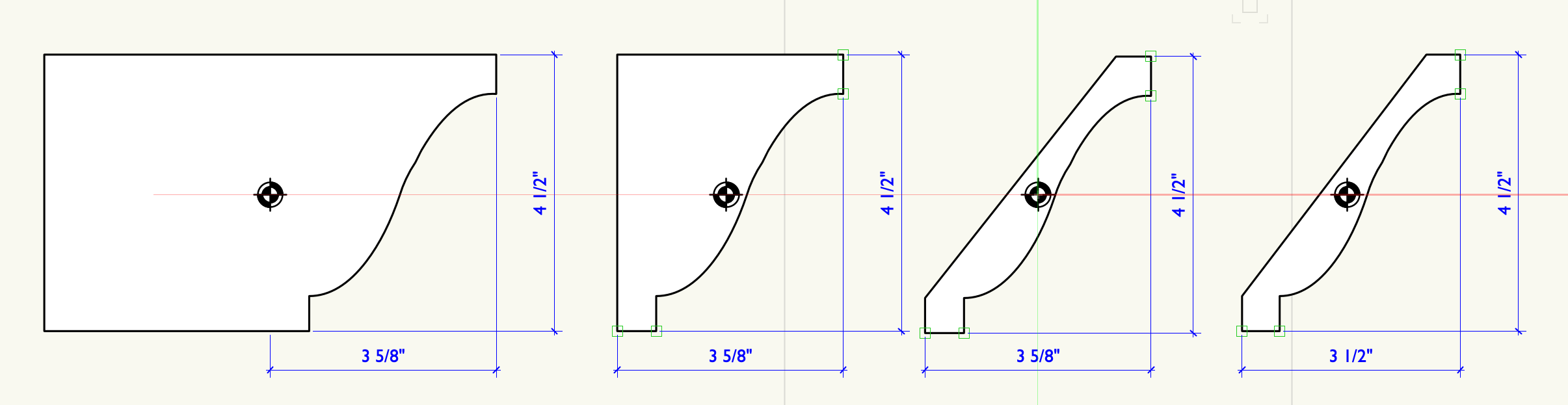
So, unless I'm missing something, always my first guess, the illustration might help. On the right is a moulding where I've adjusted the size to simplify the math. In this case, that might not mater, but when combining a number of profiles to make a crown, it can save on the head scratching. Of course, It messes up accuracy and the sections/details. The next drawing to the left is the original profile. To the left of that, I've squared it off. I have not moved the center, but I have a solid crown for no good reason. On the far left, I show what I think you're describing. I added a chunk of unnecessary geometry, but I no longer have to offset the path. In turn I also no longer have the information for a proper section without redrawing the section.This is not optimal. The second drawing shows (exaggerated) what I think @SeanOSkea (and I) would like in the EAP dialog. So, I could trace the walls, leave the line (path), select the profile, and direct VWX to extrude from the point.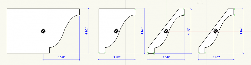
-
Extrude along a path controls
Kevin Allen replied to SeanOSkea's question in Wishlist - Feature and Content Requests
Well, then you end up with a weird profile. I do tend to make the profile a 'normal' size, sacrificing some accuracy. -
Extrude along a path controls
Kevin Allen replied to SeanOSkea's question in Wishlist - Feature and Content Requests
Exactly. If adding a crown to a box set, I trace in the plan view with the Polyline tool. Offset that line by 50% of the thickness of the moulding. Fiddle to get position and extrude. Fiddle and then Trim. For a portal. I trace the opening in Front View, Offset and place the profile in the Plan View, Extrude. There is no way to link the profile detail to the Extrude for detail drawings, which is also unfortunate. I disagree. On a film set or many interiors adding mouldings to the Wall Objects would make for faster work. This assumes that the Wall Objects would then create all of the miters. Similarly, posture rail, chair rail, door and window mouldings. Wainscoting should be wall components. In a more starts environment, other built up or applied wall details should be attached to the wall objects. I often do geometric panels on walls. Of course, once we have all of this, Forced Perspective will be a nice addition. Can't be asked? -
Extrude along a path controls
Kevin Allen replied to SeanOSkea's question in Wishlist - Feature and Content Requests
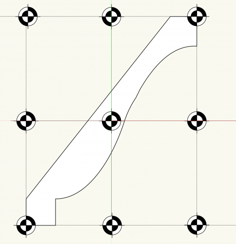
@SeanOSkea I often feel I have the same struggles. IIRC, as it's generally finger memory., I draw of place the profile perpendicular to the path. I think the control point you mention in the center point of the profile, BUT the user has to do the math. So if you have a piece of simple crown moulding that is 3 3/8" wide the offset of the path needs to be 1 7/8" (or 3 3/8 / 2 in the offset dialog). Obviously Control Points (like the 9 little dots in the oIP whose name I can never recall) would help.In an ideal world, if using Wall Objects, the crown molding, however it's composed as I doubt either of us uses a single moulding element in a crown, should be a Component and defined in a Style. @DanJansenson @_c_ @C. Andrew Dunning -
Use the extract tool to get the curve. Offset that by 50% of the thickness of the banding and then extrude a rectangle along the path
-
MSG is a typo. Should read mask. An Alpha channel is a mask, but it doesn't have to be black and white. There are many uses for, and ways to create a grayscale alpha channel in photoshop. So, If you have a 40' by 40' floor, create a texture that size in photoshop. Keep the over all resolution (DPI) low, mI typically keep all of my image based textures to 1-3Mb. That resolution is dependent on the size of my output. Create a new channel and use the gradient tool to create the black to white gradient. Save as A TIFF file and then in VWX create a new texture. Import that file, set the size to the same 40' and use Image Mask Transparency and choose this image and choose the alpha channel in the Image shader. Of course, you could create a 4" texture and change the size in VWX, but I use real world sizes to keep track of what I'm doing.
-
Create the msg as an Alpha Channein Photoshop nd save in TIFF format, then us the Alpha as a VWX mask
-
Callout Tool - Leader line points
Kevin Allen replied to Mitchell (the other one)'s topic in General Discussion
I do not think additional point is possible as you describe.