


TArchit
-
Posts
66 -
Joined
-
Last visited
Content Type
Profiles
Forums
Events
Articles
Marionette
Store
Everything posted by TArchit
-
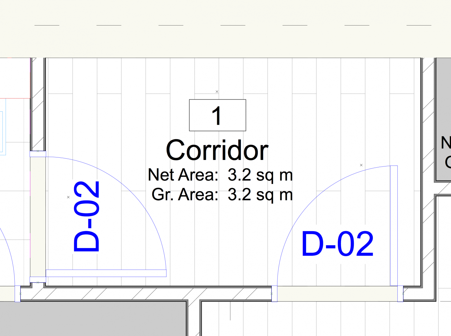
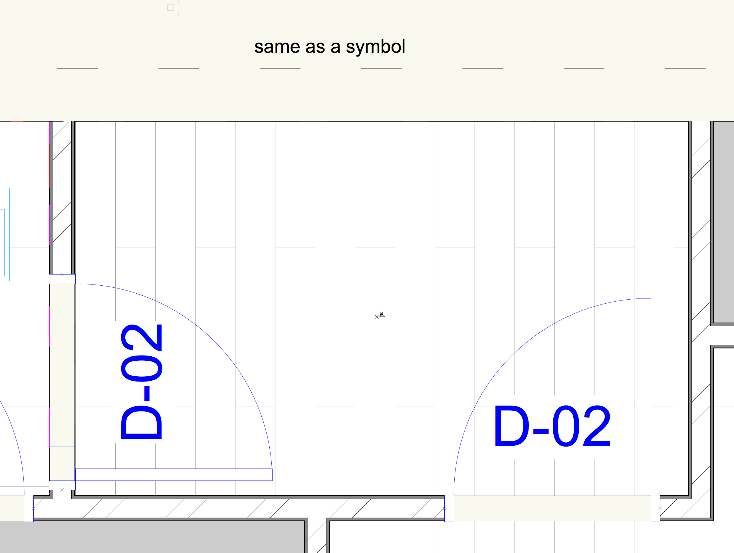
We have used the space tool to define areas within flat types. These flat types are then converted to symbols so they can be replicated around our plans. When they are outside the symbols the tags read fine however once in the symbols they change scale and are almost invisible. Is it possible to fix this?
-
@ChristiaanAnd then save it as a template rather than a symbol (or style)?
-
Is it possible to create a Railing/Fence style, in order to copy or reference across multiple floors and files?
-
Will this work if the stairs are converted to symbols and referenced into other plan files?
-
I have transferred to a faster machine with a better graphics card and it seems to be okay now. I will check those settings if I experience the same problem again. Thanks
-
If we use the stair tool to draw a stair on a ground floor (UK), how do we make it visible on the first floor plan without making the rest of the ground floor design layer visible?
-
Thanks Christiaan. I have tried that. Can this be moved into that forum?
-
Does anyone know why my model looks fine in 2D but has suddenly disappeared in 3D. When I try to select the forms it partially appears as attached? I have not changed any of my render settings. My sense is that it is corrupt. I have set up identical design layers in a new file and copied the information across floor by floor. This works and makes it visible in 3D again, however everything in the model is a reference and therefore presumably I will have to re-reference it all. Am I heading in the right direction here? Are my assumptions correct?


-
I also agree with the original poster and think that the stair tool is sorely lacking. I struggle to make changes which are mathematically correct because too many supposedly unlocked parameters are constraining the adaptability of the stairs. For most stairs I find that the key and fundamental parameters are the overall height and width of the stair and the depth of tread. Everything else is secondary and should adapt in relation to these three parameters by default, not dictate them. This should be the starting point. Riser height is another key factor and is of course constrained by building regulations. This should be a separate calculation which is simply overall height divided by number of risers, and not affected by anything else other than perhaps a user override for custom editing. Currently other factors such as stair length appear to have an equal weighting with these fundamental parameters and it makes editing stairs highly frustrating.
-
@JimWNoted
-
Does anyone else find the stair tool awkwardly frustrating to amend and control each of the parameters in relation to other parameters? I struggle to make changes which are mathematically correct because too many supposedly unlocked parameters are constraining the adaptability of the stairs.
-
How do we make a custom sheet file, so that when we create a section view port from a clip cube for instance, the section is created on a sheet file with the correct paper size and settings and our title block already set up?
-
What is the best way do show / extract a reflected ceiling plan from your model? Can you flip the direction a design layer is viewed in a viewport so that it looks up rather than down?
-
Having thought more about this it seems fundamental to working with other consultants effectively, especially on larger projects. I haven't worked with a single structural engineer in the UK who uses BIM and doesn't use Revit. How do people usually reference structural consultant models in their plans? Surely we shouldn't have to redraw their structure if over multiple floors?
-
Yes that works, thanks Wes
-
Yes that is excellent and exactly what I was after, thanks Matt!
-
@itchy yes let's hope so. It does seem that something like this would be very useful
-
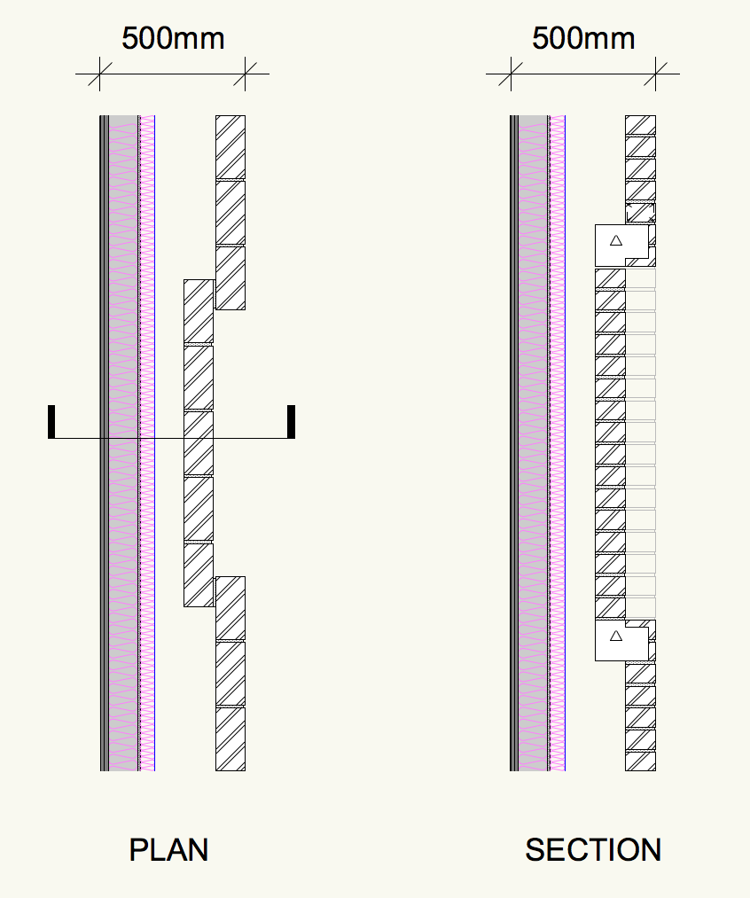
Thanks for the replies. It is a recess that we are trying to create rather than an opening. I've attached a basic plan and section indicating the external wall type we would like to create. These occur many times across all of our facades. @Pat Stanfordthe 3D Reshape tool seems like it might work. Where is it located?
-
When I subtract an extruded rectangle (a box) from a wall, the wall seems to cease being a proper wall style and instead becomes a basic 3D object. Is this what I should expect to happen? Is there a way for the wall to retain its full properties after subtracting from it?
-
@JimW thanks for the tip. Even when this is activated I still sometimes get Parallel and Vertical options when all I want to do is ensure I am drawing orthogonally. Seems like a 90° lock tool would be useful .


-
We are drawing multiple flat types as individual design layers which are then referenced into a large shell and core model as design layer viewports. How do we set the plan, section and elevation sheet files up to include these design layer viewports?
-
The structural engineer we are working with uses Revit and they model elements such as shear walls as single objects across multiple floors. Ideally we will reference their IFC model into our files so that we don't have to model any structure. Revit has a level system that slices the model with a variable cut plane at each floor level to isolate that part of the structure. Is it possible to achieve this in Vectorworks? What is the best way to control the visibility of their model files across different floors?
-
Is it possible to lock the direction of drawing orthogonally to the x and y axis? I am aware you can hold down the shift key although this is only a temporary measure, and most of our drawing is currently orthogonal.
-
Great, thanks everyone
-
@Wes Gardner how do you mean exactly. Would I have to create a wall on a new class and switch it off?

