


JHAM
-
Posts
24 -
Joined
-
Last visited
Content Type
Profiles
Forums
Events
Articles
Marionette
Store
Posts posted by JHAM
-
-
I did not realize you could have Data Tags attached to objects in the model while in Annotations until your comment and I tried it. My mind is officially blown. I must have missed that part in skimming through all of the 2019 material. This is a game changer!
Not sure if it has been submitted as a bug.
Thanks!
-
Sorry, I should have updated this post when I found the work-around. The solution I found is to use Data Tags to label the spaces. You create the space, and don't assign a label to it in the Spaces Dialog, but you can attach a Data Tag to each Space. You can then control their visibilities through classes. If you attach the Data Tag in Design space, it will use the properties of the Space object to get information, so you can assign a ceiling height, area, etc.
It took me a little bit to get it right, because I have Space Label symbols that I've been using for plan vs RCP, so I had to add those to a default library file in order to use them through Data Tags.
It's not as clean as it was formerly -- you have to keep the "Show 2D Boundary" checked. But since the Data Tags are not included in the "Room-name/number" class anymore, you can just turn off the space class.
good luck.
-
 1
1
-
-
Is my office the only one that doesn't use stories??
In the 2019 Object Style Library, there are now 2 folders for Imperial Wall Styles -- Story Bounded Walls and Fixed Height Walls. Yet, the Fixed Height wall folder is woefully lacking in styles.
We try to use as many of the given VWX wall types as possible, and then modify them as needed for individual projects, so this new feature is super frustrating.
My options are either to:
1. Use stories -- which is stupid for 1 floor projects, and it is not in our current workflow/I don't fully understand how to use it correctly, TBH.
-- also, for projects with just 1 story, this doesn't work anyway, because the top of components are still automatically set to the height of story 2, which doesn't exist. So all of the components in each wall style has to be changed.
2. Import all the wall styles I'll need and then edit the Wall Component "Component Top Restraint" to be "Relative to Wall" in every single wall style.
There has to be a better way -- am I missing something??
-
I do this the same way @Boh does. Just go down the list of classes and delete them, reassign all objects on that deleted class to one of my already established classes. Then I have clean linework and only my own classes in the drawing -- no extraneous CAD classes.
As an added step, I also like to keep any CAD linework from outside sources (as-builts, consultants, etc) in their own files and then reference them into my clean file. Then I really don't have any cross-contamination. Start by purging all of the unused classes.
SOMETIMES, if I am lazy, I'll import the CAD to a blank file and save it. Reference it into my project file, and then change the visibilities of the CAD classes in the referenced viewport. When you reference something, it doesn't bring over all of that file's classes, they just show up in the OIP of that viewport. If I still have the referenced file open, I can just click back and forth -- learn which classes I need to turn off, and then turn them off. Only have to do that once.
Another way I just thought of is instead of starting with a line and finding out what class it is on, do the opposite. So in the Navigation palette, change Class Options to "Active Only" or "Gray Others" and go down the list of classes, changing the attributes as you go.
-
1
-
-
Try using the "Clip" tool instead (Option+c). I never use the trim tool and exclusively use the Clip tool. You just have to select the object you would like to clip first and then activate the tool. Then draw a rectangle where you'd like to clip it (snap to the jambs to use them as guides -- no drawing temporary lines). You can select if you'd like to clip and delete what is inside of the clipping rectangle, or just clip and leave it there.
I would highly recommend using the wall and door tools, though. I'm not sure what VW12 looks like, but the door tool will automatically cut the wall when inserted. Switching from drawing only in 2D in VWX 2013 to 3D in 2017 was the best thing our office ever did! If you get started using the wall and door tools now, while still drawing in 2d, you can get used to that process of creating walls and windows to fit your design parameters. Then if you decide to switch to 3D later, the transition will be much smoother.
-
Ah ok! Thanks for this. Data Tag was the key. I used the Data Tag in the Design Layer, and it works the same way as I was originally using space labels. The only issue I'm having now is that you have to keep the 2d space boundary on in order to edit the information showing in the tag. I'll just have to create another class so I can hide the 2d boundary in viewports.
One head scratcher though is why did they keep Space Labels in the Space Tool if it isn't functional and they want us to use Data Tags for everything?
-
Yep, I'm having the same problem. Just posted a new topic about it.. and digging around. This appears to be the only problem I'm having with converting 2018 files to 2019..... so far.
-
Has anyone used the space labels in 2019 yet?
I usually have 2 labels for each space (Plan and RCP) and control the visibilities with classes... But this doesn't seem to be working in 2019. Both labels show up no matter what classes you have turned off/on. You can still assign each space label to have its own class, but I can't figure out why you would do that, as you can't control the visibility of each label via class visibility.
I feel like they changed the way spaces work, when they updated how all tags work... so I am missing something.
-
I think class overrides in viewports should be the exception, not the rule.
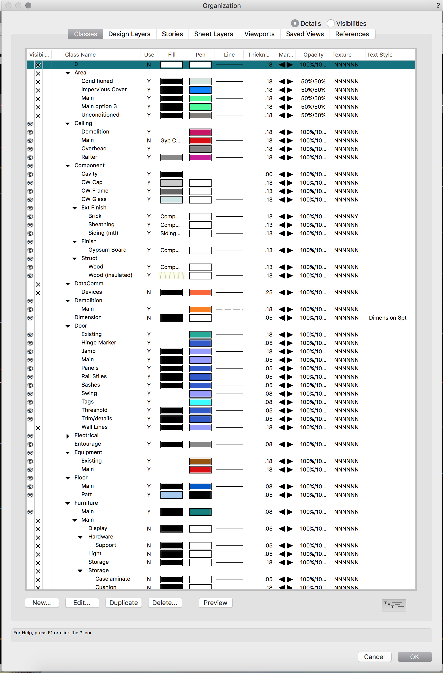
You should start by giving all of your classes a corresponding lineweight. In AutoCAD you give each color a lineweight for plotting, but in VWX you give each class (layer equivalent in CAD) a specific lineweight. Then, each object you create should be assigned to a specific class and then it will take on the properties of that class. If the lineweight you've applied to an object doesn't look right in one viewport, you can override the class settings in that viewport. If it doesn't look right in any viewport, then you can just change the settings of the class, and every object that has the properties of that class will adapt accordingly.
See image below for a snapshot of our class settings:

If you've set up the classes the correct way, then when you toggle black and white and print, it will print with the corresponding lineweights.
We've developed these class settings over years in our office, and they are just default in our files now. I'm pretty sure you could find a sample set of class settings somewhere... I'll look as well.
Are we getting closer to answering your question or have you already set up your class settings?
JH
-
2
-
-
Not sure that is possible. If this were Revit, you could do that, but alas, VWX only allows a symbol as-is and doesn't allow parametric constraints.
Do you have an image of what you are trying to achieve? An image of the jamb symbol?
What I typically do, is just set the jamb/sill/head settings as close as possible to what I am trying to achieve and then let the Window Jamb/Head/Sill Details do the work. If you don't need the special configuration to show up in elevation, then just let the plan be a graphic representation (you should dimension to the center of the opening anyway) and show the configuration in a detail.
Best
-
I think this is the solution you are looking for.. You can quickly switch back and forth from color lines to black and white (for printing).
On the toolbar at the top there is an arrow that will expand a drop-down menu with various display options:
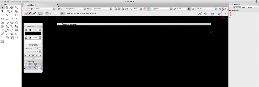
Add the one called "Black and White Only"
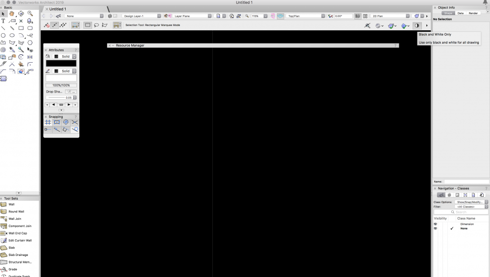
You can then click that button to toggle back and forth between color and B&W, and use cmd+P instead of publishing.
You can also toggle the background between black and white, toggle with "zoom line weights" and a bunch of other stuff.
Have fun! I also switched from AutoCAD to VWX about 4 years ago. It was frustrating in the beginning because you are used to doing something in a specific way, but I now LOVE vectorworks. I feel like it is the best of 3d and 2d.
Let me know if you have any other CAD --> VWX questions
Cheers,
Jena
-
1
-
-
Just going to throw in our 2 cents here.
We are a small Mac based office and use Project Sharing sparingly since there can be so many hiccups. But the best solution we have found is to manually check out whole layers or sheets while working instead of letting VWX automatically check out individual object as you are working. You can right-click on a layer or sheet in the Navigation panel and click "Check Out." Then, as soon as you are done working on that sheet/layer, you save and commit and release it back to the project file.
This would help you if you set up your files so that structural elements, restaurant/hotel rooms were each on their own layer.
I personally set up a short-cut on my machine (shift+command+s) so that when I am working with project sharing, I just default save and commit every so often instead of just saving to my working file. At the end of every working day, we check each others files to make sure our latest updates are loading correctly in the Project File.
Hope this helps.
-
1
-
-
On 6/22/2018 at 5:18 AM, MRD Mark Ridgewell said:
Thanks for sharing Matt, looks interesting. Will give it a try.
As an extra bonus, just found that 'shift+command+R' rotates an object 90 degrees !
Command+L does the same thing, and its a little easier command!
Also added bonus, Shift+Command+H flips horizontally and Shift+Command+V flips vertically.
Cheers!
-
Nevermind, I just realized that you can ungroup them!
game changer.
-
Hey all,
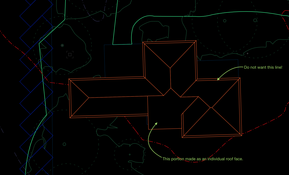
I usually use the "Roof Face" tool instead of "Create Roof" but I would really like to use "Create Roof" for a fully connected roof on this project. My biggest problem is that I have double lines at the edge of the roof. One inside at the "edge of roof"/bearing point and one at the edge of the overhang. The only way I can get the double lines to go away in 2d is to create a roof 12" larger than the edge of my walls with no overhang. Is there any other way to adjust this? I'd love to be able to keep the bearing part of the roof the same and then play around with the eave depths, but I can't have this double line situation showing up in my roof plan. The only other solution is to just make all of the faces individually.
Am I overlooking some easy solution here?
Jena
-
Thanks for the response.
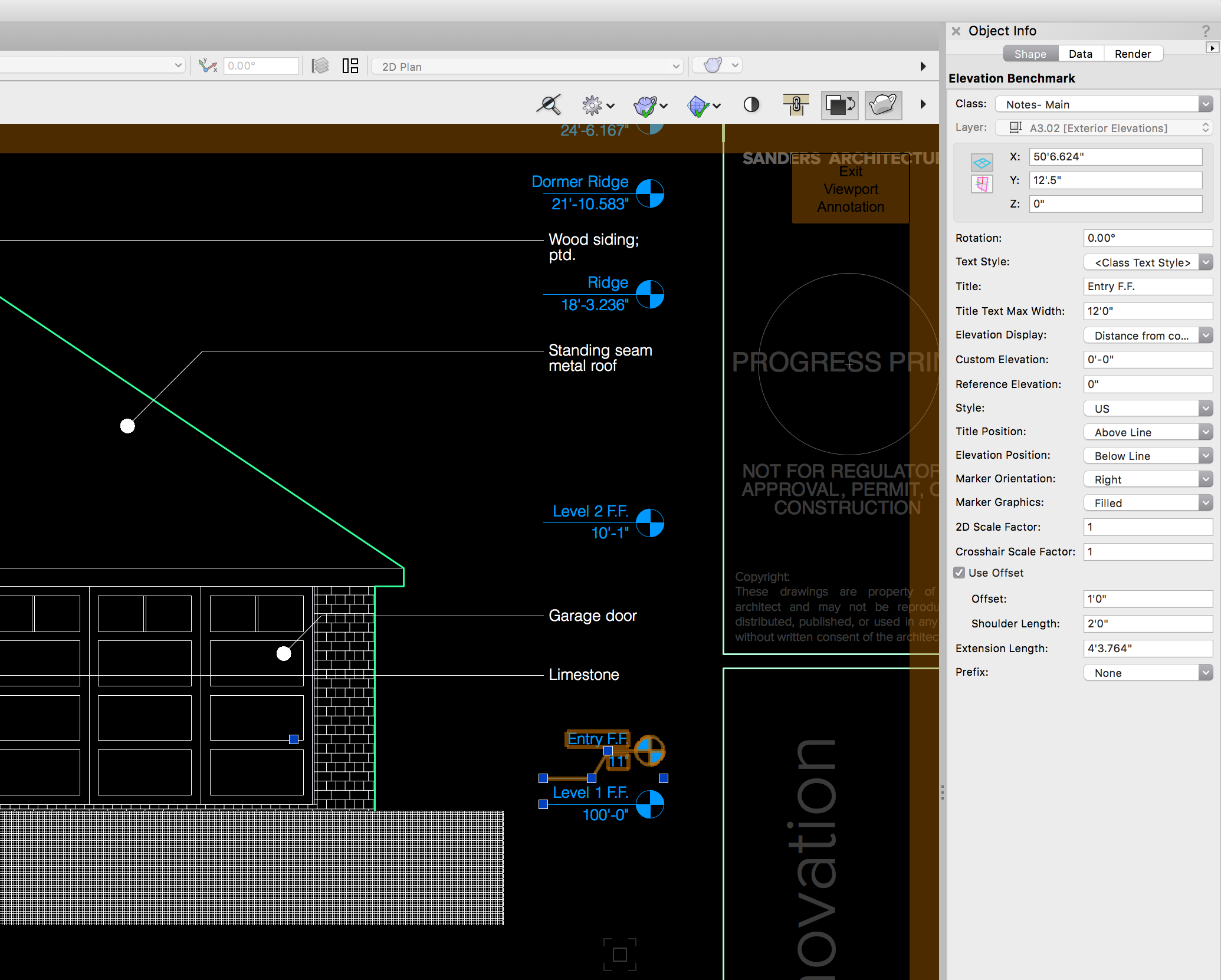
Ok. I got it to work -- the trick is to set the reference elevation to -100'-0" (negative!) instead of 100'-0" (positive!).
QuoteTake care to set the option to y or z value as appropriate.
Thanks for this ^^ I was setting the FF to be "Custom"!
-
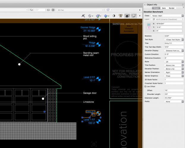
Hey guys,
I feel like I am still learning how to set elevation benchmarks! In an elevation viewport, I usually call out the F.F. first and set it at 0'-0". All other benchmarks are placed above and I use "Y-value relative to reference elevation." This usually works perfectly because my F.F. is on the bottom layer with a layer elevation of 0'-0".
However, on some projects, we like to set the F.F. to 100'-0" if there are elevations below the F.F. (so you have elevations at 99'-6" instead of -0'-6"). How do I then use the elevation benchmarks to automate the numbers, so I don't have to go in and adjust all of the benchmarks to "Custom"?
Do I have to go in and change the lowest layer to an elevation of 100'-0"?
Thanks,
J
-
4 hours ago, Urbanist said:
I'm certainly missing something since I don't understand the need for this. A non-professional client does not understand the obscure and funny hinge marker anyway and surely the professionals use door schedules in combination with floor plans. Industry practices of course vary.
You're right that clients do not usually understand this at first, but they are teachable and some catch on fairly quickly. Either way, a client's perceived understanding shouldn't dictate how we do our work/drawings. The hinge markers give an added layer of information in elevations -- sometimes elevations can read a little flat without them. They also are a signal that that rectangle in my drawing is definitely a door and cannot be mistaken for something else. Contractors need all the help they can get.
-
2
-
-
13 hours ago, Alan Woodwell said:
This is the step that is no longer working in 2018, the marker refuses to use the line type of the set class.
Your other suggestion is great -- I'll use that for now until the bug is resolved.
Cheers!
-
ah! Thanks!
-
Just downloaded 2018 and I am migrating over..
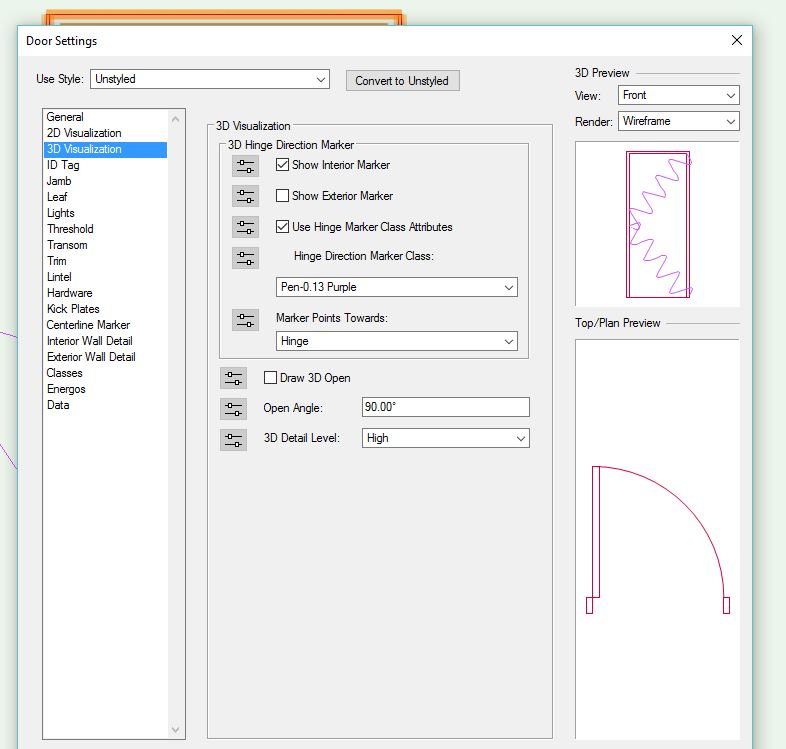
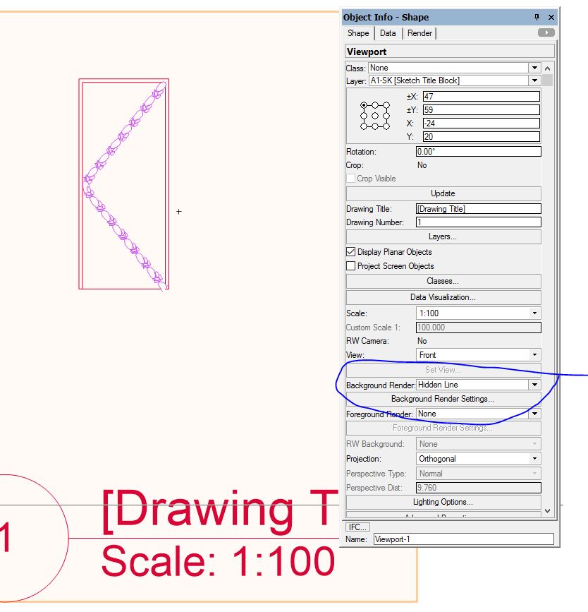
Tell me if I am missing something, but I cannot get the Door Hinge Markers to show up as dashed line type in an elevation (hidden line render). In the door preview, the default preview render mode is Wireframe, and the dashed line shows up correctly. As soon as I switch to Hidden Line, it becomes a solid line.
I use a class type for the hinge marker and have tried various line types, but I cannot get any of them to show up as anything but a solid line. Anyone else having this issue?
Don't want to complain too much, because my biggest pet peeve with previous versions (detail callout) was resolved!
J
-
2
-
-
Hello all,
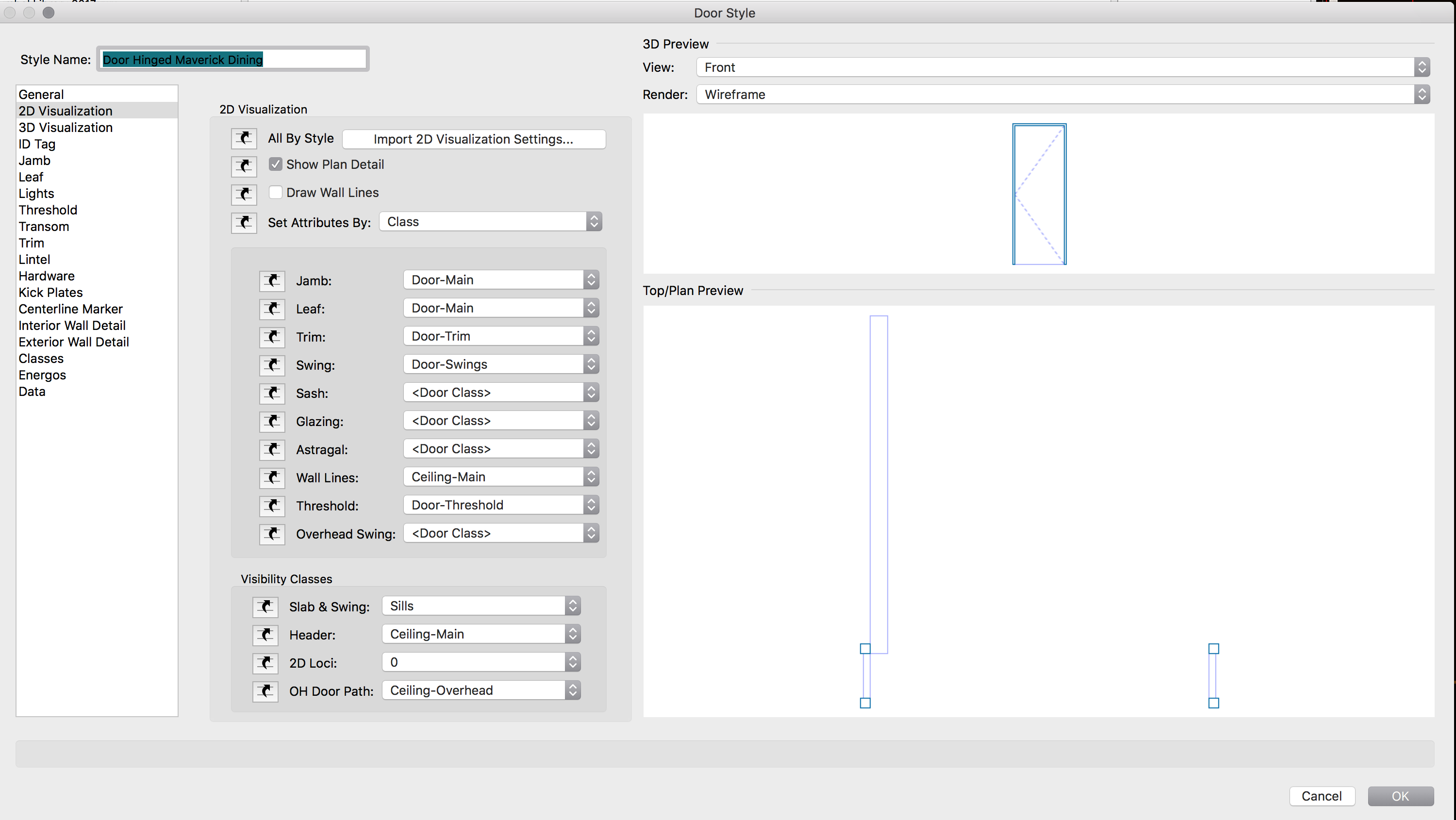
I've searched the forum, but haven't found a solution for my specific problem. I've created an RCP with the floor layer on top, and ceiling layer below. I would like the door headers to have a solid fill, so that they obscure the modeled ceiling structure. I've turned on Ceiling-Main class, but the Wall Lines that appear are only lines, they don't contain a fill. So my ceiling structure is showing up where the door header should be.
I've tried creating a new Door-Threshold class with the settings I would like to see, but I can't figure out what the Door Style 2D visualization settings for the Threshold controls.
Attached are my Door 2d Visualization settings and a screen shot of the RCP.
I'm using VWX 2017, SP-3.
Any ideas?
Thanks,
Jena
also, don't ask me where the room labels are. they've disappeared, yet again.

-
Hi all,
Our office recently made the jump from VW 2013 (2d only) to 2017! We have been slowly changing our workflow to a more BIM approach and are changing a lot of standards in our office.
We'd really like to hear how your workflow works with placing your Architect's stamp on the final set of drawings.
In 2013, we had a 2d symbol of our Titleblock, with a 2d symbol of the stamp located outside of the sheets margins. We would print with a "Progress Print" stamp in the titleblock until we were ready to issue the documents, then we would edit the 2d Titleblock symbol and move the stamp into the titleblock and print area. This worked well because the referenced 2d symbol would update in all drawings, on all sheets. It did not work well when we needed to send DWG files to our consultants. The 2d symbols would move with the DWG.
In 2017, our titleblock is no longer a 2d symbol, and is now integrated into the sheet border, the way it should be. Our stamp and "progress print" are both inside the printer margins, but on different classes that we could toggle on and off. This seemed like the best approach at the time, but it is still not satisfactory.
We are having problems with keeping the stamp class off. It is off in all of the saved views, but as soon as you enter a viewport that has the class on, when you navigate back to the sheet layer, the class stays on. We cannot find a way to save the class settings relative to the sheet layers, and the stamp keeps popping back up. We've found where we can easily turn off the class in all of the viewports at once (right-click the class, visibilities).
In addition to the class settings frustrations, the stamp is still possibly in the drawings when we export to DWG for our consultants. We are debating adding the stamp at the very end in adobe -- taking it out of Vectorworks completely -- but still aren't satisfied.
Our question -- is there a better way? How do you handle placing your seal in the final documents?


DIRTY LINES in VP
in Architecture
Posted
If you haven't resolved this yet....
It looks like the hinge markers for the windows are turned on. If you have a class for hinge markers, just turn that class off in the VP.
If not, turn off "Show Interior/Exterior Marker" for each window in the window settings: 3D Visualization: