

Wesley Burrows
-
Posts
445 -
Joined
-
Last visited
Content Type
Profiles
Forums
Events
Articles
Marionette
Store
Posts posted by Wesley Burrows
-
-
8 minutes ago, Darrell Henry said:
The frustrating thing is that I can take a connected load, option - drag it to a new location to add a second instance, and that instance does not connect.
I totally agree on this. I also get erratic results with option + dragging, and the mirror tool, which kills me cause I use it all it time. If I mirror something, say 4 fixtures across the center line on the same hanging position, usually one of the mirrors attaches its load position to it's old location and the mirrored geometry has a z height of zero or something arbitrary, while in top/plan the geometry shows in the correct location (but wrong Z height and the load is either not attached or attached to the wrong former location)
-
17 hours ago, Darrell Henry said:
Anyone else noticed that the insert truss tool for BW seems to add .03 degrees of rotation?
I have not encountered this.
QuoteAlso there needs to be a tool to attached a load manually to the truss system. I have lighting instruments that won't attach for love or money...
As Rob said you can do this with truss (either the PIO or braceworks truss) converted to a hanging position. According to Moritz Staffel (the creator or Braceworks) in his presentation at Vectorworks Design Summit, the best practice is to use Geometry rather than a Symbol when creating positions for Braceworks as to avoid potential errors.
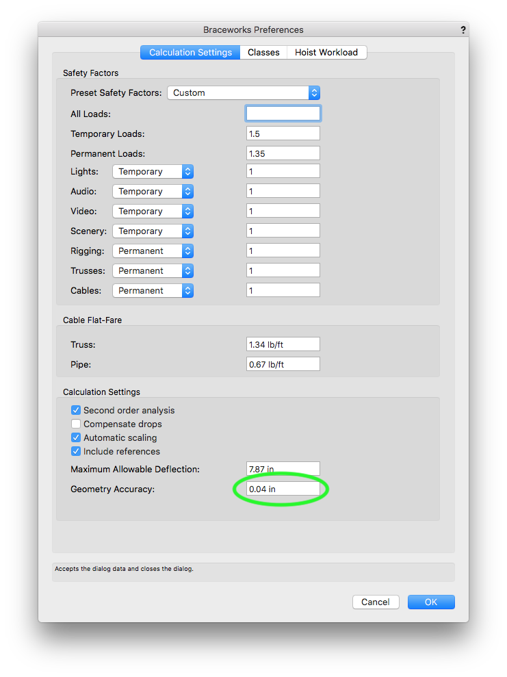
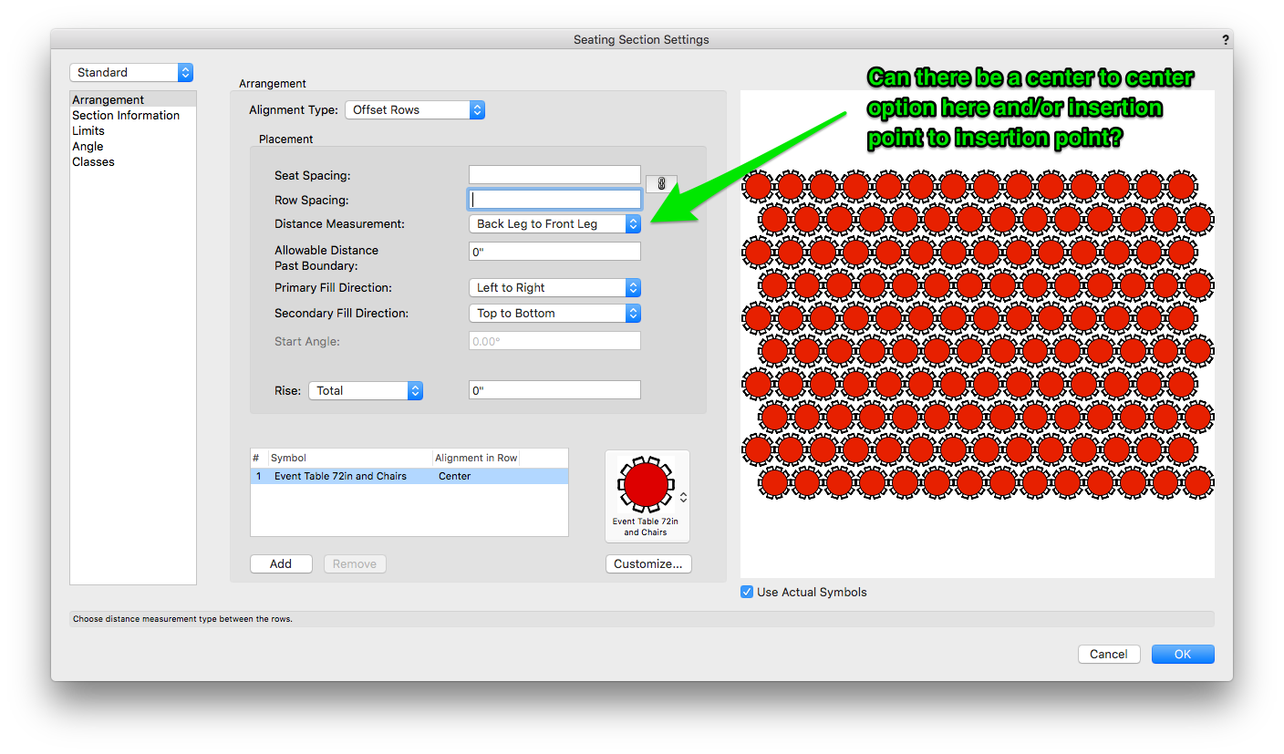
The thing I've learned from others and general messing around, (and was a source of confusion for me) is that you can't "attach" an item to regular braceworks truss or the truss PIO. However, the weight is automatically calculated and it assumes an item is attached if it is within a certain user-definable tolerance/distance to the truss. I believe this is the setting (circled) in the below image.
The advantage of the hanging position and attach load is being able to show fixtures out of position for clarity while still calculating weight from their true truss location. This also allows the ability to move the position and have everything attached to it move with it. (Though I believe there are a few bugs with this to be address in a forthcoming service pack) This has been my understanding and experience anyway.
-W
-
Just now, Selin said:
Well, the engineering would be me
") I haven't seen any bug reports about this or anything else from tech support. I can't reproduce this myself either, so my hands are tied.
I haven't seen any bug reports about this or anything else from tech support. I can't reproduce this myself either, so my hands are tied.
I can only guess why merge might not be working with geometry changes. When you add solids, convert something to a symbol etc. you are essentially creating a brand new object and merging won't work. But, you're saying you are doing a fresh export every time so this exception would be irrelevant anyways.
@zoomer after you export a vwx file to cinema, can you please try to export that file from Cinema to FBX? Are the materials still missing?Hi @Selin. I've been talking to Joseph Block, he said he was able to reproduce the error with my file and forwarded it to engineering. JIRA VSS-60589
-
8 hours ago, markdd said:
I can confirm this as well. Will you submitthiss as a bug?
Do you know about autoplot tools? These tools have several other ways to distribute fixtures.
Yeah, I've played with them a little bit, But not for a while. There wasn't much in the way of documentation and I didn't have a bunch of time to experiment with them.
I just submitted this as a bug.
-
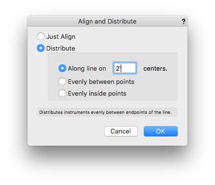
When using the "Align and Distribute Items" tool from the Spotlight tool set, VW 2018 SP1 crashes everytime I use the tool with fixtures on a hanging position. The tool seems to work if the fixtures are just in some open space. These were the settings I used.
-
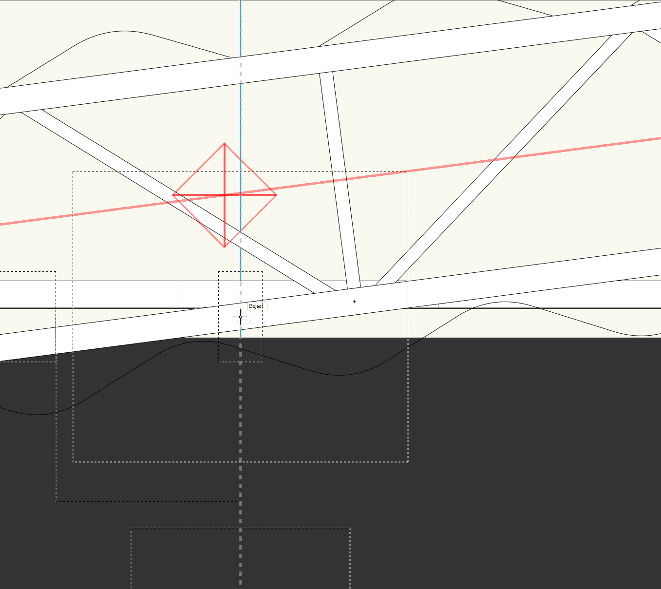
This really doesn't seem like the correct behavior. Support told me they believe it's operating as intended but I feel like it's incorrect. In CAD software I should be able to place the hoist with 100% precision to the beam while maintaining the center snap not have the tool dictate to me where the beam is. Anyone else?
-
9 minutes ago, JimW said:
Give this a try now! If it works or doesn't, please reply back with that info as well as what OS and what browser you are using.Works on Mac OS 10.13.1 and Chrome Version 61.0.3163.100 (Official Build) (64-bit)
-
On 10/14/2017 at 2:35 PM, Art V said:
Confirming Deck's observation.
I'm having this issue as well with 2018 SP1, first I thought it was removed but it's good to hear that is not supposed to be the case. Because I immediately created a new default template for starting up Vectorworks I did not notice it is still there when creating a blank document. I just tried and when creating a blank document that origin icon is still there, it's not there with templates created in VW2018 and opened through File>new and then choose a template.
The odd thing is that when I open a VW2017 template through File>open (select file and have it converted to VW2018 format) the origin icon does show up.
When I open a VW 2018 template file using File>open the origin does not show up show up.So it seems to be an issue with templates created in VW2018.
When opening a normal VW2017 file the origin icon appears, once saved as VW2018 and opened again after it has been closed the origin icon does not appear.
Another observation, once you have a document open where the origin icon is visible, it will then also be visible when other documents are opened after that file in the same VW session as long as that file is open. Once all files have been closed and a VW2018 fiie is opened again the origin icon no longer appears.
Files opened in VW (and still open) that do not show the origin icon and opened before the file that does show an origin icon will not have the origin icon appear afterwards, so it seems to be persistent with the document.
Using Ctr-9 works without issues.
I too confirm these observations. This just started happening with me on 2018 SP1 also.
-
I don't know if this helps, but you can insert a 3D door with the door tool using your required parameters and then ungroup the result, which will then just become a 2D set of polygons that look like a door?
-
Does anyone else run into accidently undocking palettes and not being able to re-dock them without restarting VW? It also seems way easier to inadvertently undock a palette than in previous releases.
-
Thank you@Yordan Kostadinovfor the detailed answers!
-
I'm curious, for those of us that have to deal with larger seating layouts regularly, how do you approach it? Do you start a ballroom or convention center layout with a giant rectangle and then start cutting in aisles for fire code etc? Build it a section at a time? For that matter which of the three different seating layout tools do you use?
A few times a year I'm doing layouts that max out around 15,000 seats. This get's to be a special kind of bloated and difficult if you were to try and do as an enormous rectangle.
How about bowl style seating layouts. Such as similar to the below image? Though this shows round horizontal aisles usually (in my situations) it's more of angled straight lines to form the "curve".

-
 2
2
-
-
2 minutes ago, Yordan Kostadinov said:
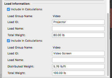
In the image is used the Truss item. Braceworks creates a model of the structure including the new Truss item, the known Straight and Curved Trusses and the Lighting Pipe, the Hoist as drops and all object with Load Information as weights. Braceworks assumes that both the Screen and the Projector are attached to the trusses. But they are not associated as when using Hanging Position for move or rotate.
So it does auto-associate with the truss pio without needing to be a hanging position? As in, it'll calculate the weight but not move with the truss if it the truss gets moved? I guess the thing I'm having a hard time with, is running system checks on objects and getting seemingly random load not attached errors. It's somewhat difficult to tell what is actually attached and what is not. There are even lights with the blue remove load arrow that flag with a label as load not attached. My company is purchasing Braceworks for me next week and in the meantime I've been trying to get some projects already in progress setup for it in advance. I'm currently just using the built-in Spotlight braceworks commands.
-
4 minutes ago, Yordan Kostadinov said:
Unfortunately for Vectorworks 2018 is planned to be able to attach only the video screen. If you need to include the projector properly in the calculations, you need to set it's location via the OIP parameters for Projector distance and vertical position. Note that Braceworks calculations don't need a Hanging Position, it's meant to allow hang with offset (via the Witness Lines) and also object associations. In the attached image no Hanging Position is used.
Is this braceworks truss? Or does this work with the truss PIO? Does it just auto associate with the nearest truss?
-
In the distance field there really should be an option to use center-center and/or insertion point-insertion point. For table layouts back leg to front leg and front leg to front leg are completely arbitrary.
-
3 hours ago, Mike Wright said:
Video screen PIO and braceworks compatibility is coming in SP2 apparently
Good to hear! Thanks Mike!
-
When you use the Video Screen PIO it shows two different weight fields, one for the screen and one for the PJ, which leads me to believe you should be able to attach the screen as a load on one truss and the PJ as a load on another. In reality, I have haven't been able to get this to happen. It all assigns as one item (as far as I can tell) so I've added load items for now. Should they be attachable separately? Or is that something that is in the works?
-
1 minute ago, Yordan Kostadinov said:
The problem with the Weight of the LED Screen is fixed for the upcoming SP2.
Awesome, Thanks!
-
Tech support has confirmed my export issues too, but so far, only in the example files I've sent. Working with engineering to figure out what's going on. I'll report back when I hear more.
-
1 hour ago, C. Andrew Dunning said:
Wesley -
Your request makes perfect sense. At the same time, just shedding some light on why things are the way they are...: Different users use the tool in different ways. Some users create entire walls and see each "Module" as an individual panel. For that application, "Module Weight" could then be used to calculate a total. For other users, each instance represents a single panel (part of a wall) and "Weight," as it is now is the weight for that panel and having to know the weight for each module isn't really practical. For this latter approach, users can then generate reports that can both track data for the individual panels (tool instances) as well as calculate weights.
Make sense??
Yes that makes sense. As with anything, the per panel weight shouldn't be the only way to calculate the weight, but it would be great as an option. Not forced :-)
-
It would be great if the Soft Goods Tool Set could calculate the total weight value of the drape based on a standard of measurement for drape/fabric. For example Rose Brand shows their weights as lbs or oz per linear yard (US) obviously it should also work similarly with meters. It would be wonderful if the tool could take information such as that and convert it to the proper total weight/lbs per foot. Based on the total square footage of drape. Currently I have to take the ((L X W) / 13.5) x lbs per linear yard to obtain the total weight and update the field anytime a drape adjustment get's made.
EDITED TO ADD:
The 13.5 comes from dividing the width (in inches) of the spec Rose Brand fabric (54"). So (54 / 12) * 3 = sq feet per linear yard. If the spec fabric on which the weight is based is a different size. Say 60", it would be (60 /12) * 3 = 15. So 15 would replace 13.5 in the above equation.
-
1
-
-
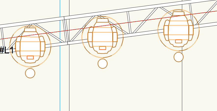
When trying to snap a motor via the red insertion guides to a beam in a drawing (see the vertical light blue line in the photo) even when my cursor snaps to the light blue beam (as pictured) the red insertion square does not line up with the beam, it's offset slightly to the left. So the hoist always inserts slightly off the beam. Is this a bug?
-
It would be great if I could put the per panel weight in a field for this and have the plug-in keep the total weight field correct based on the number of panels as things change, It seems silly I have to have to manually calculate the total weight anytime the LED wall config changes.
-
On 9/25/2017 at 4:31 PM, Scott Parker said:
Additionally, I'd like to at a keyboard shortcut to the Attach Loads command.
This +1000. I've had to manually right click / attach loads for almost every device on my hanging positions. They don't want to auto-attach no matter what. Even lighting devices, they work about 1/2 the time.
Spotlight - Align Distribute Tool Crashes 2018 SP1 & SP2
in Known Issues
Posted
FWIW This has been filed as VB-146635. @JimW, I don't know if this thread should be moved to known issues or if it should hang here.