


Moritz Staffel
-
Posts
158 -
Joined
-
Last visited
Content Type
Profiles
Forums
Events
Articles
Marionette
Store
Posts posted by Moritz Staffel
-
-
Hi @Richard1
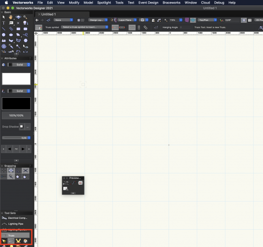
You need to use an object that actually uses symbol inside Vectorworks.
A good example is the Truss Tool.
-
Hi @samuel_ellis,
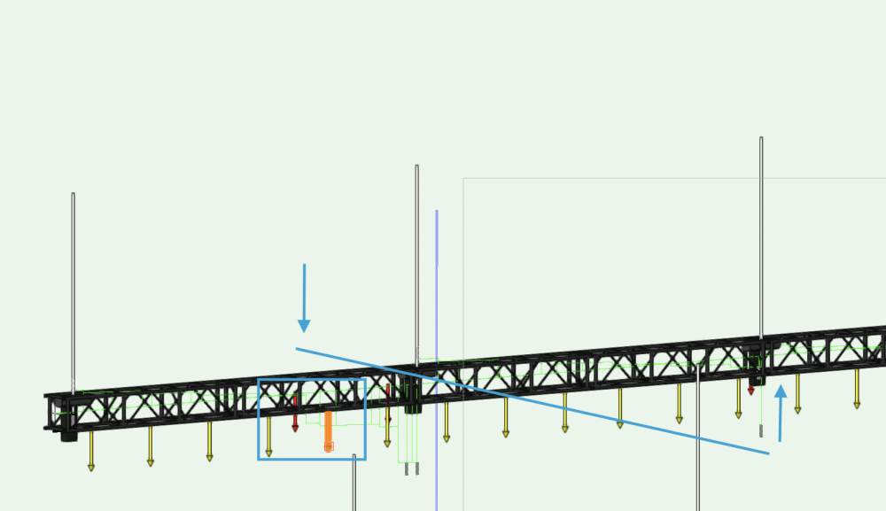
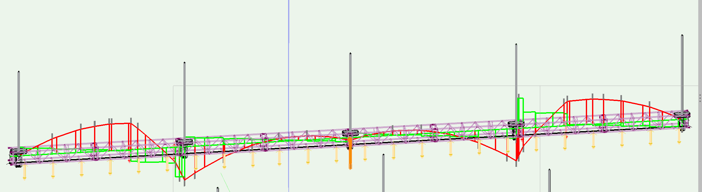
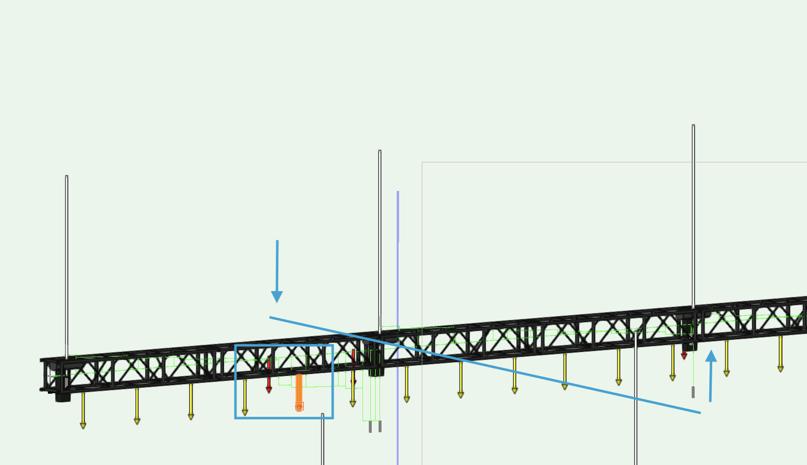
I have checked your file and from what I see the Braceworks calculation reports are right. You see that the moment and shear force looks like aspected.
What is happening that the 2 (heavy) audio loads on the outer truss segments pull the middle hoist up. I have attached a screenshot that show the lever which is acting there.
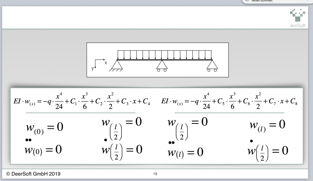
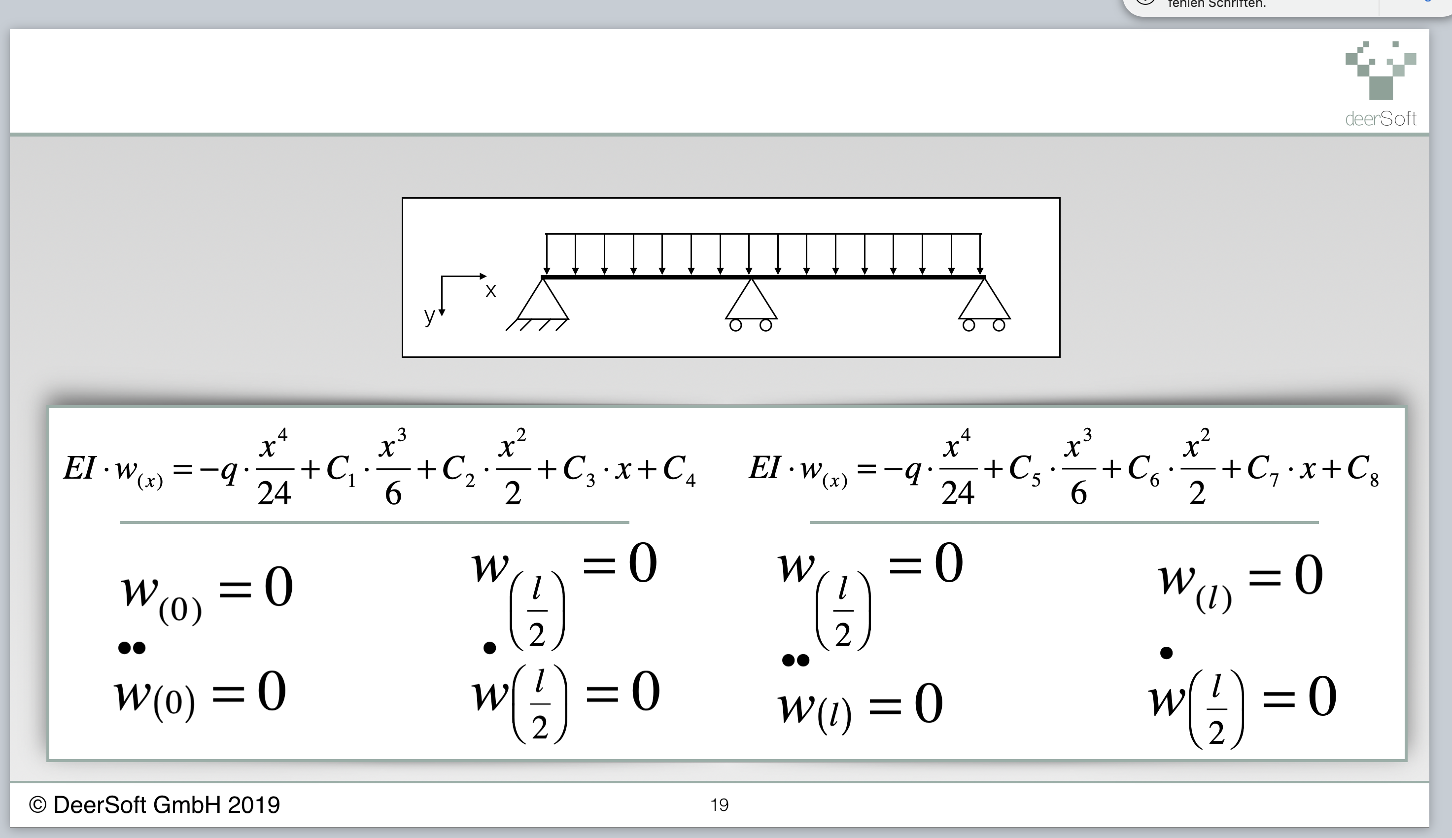
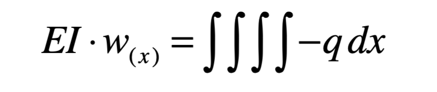
I also attached some parts of our Braceworks training where we educate about the math behind Braceworks. I would invite you to such a session to give you some more insides what happens inside a Braceworks calculation. Just send me a PM to set up an meeting 🙂


-
 1
1
-
-
Hi @Samuel_Ellis,
Braceworks uses the FEA Method to calculate the forces and deflection.
From the Report you have shared I see that you use rigid cross sections.
Can you share your Vectorworks file?
-
thanks for your post. Unfortunately this is a a limitation from Braceworks.
Both the rigs are recognized as 3D structures, and Braceworks requires for 3D structures at least 3 supports that are not in line.
This is the case for the left rig, but not for the right.
The only way to get this system calculating in Vectorworks 2019, is to place a third support on this like you have done for the left rig.
I have filed a Enhancement Request for this in Vectorworks.
-
1 hour ago, Martijn Wingelaar said:
@ Moritz and all other users.
Again.
A bad Tool.
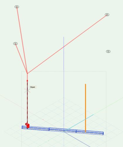
So what if I want to create a 3 leg bridle and all the hanging points are at a different height?
Like in a spaceframe with an extra level? "Image 1".
Leg 1 at 11m, Leg 2 at 15m, Leg 3 at 19m.
This happens a lot weight wise.
Now in the tool I have to give a trim height that's for all the legs.
This is the wrong way around.
Snap to a House Rigging Point or Structural Member.
Set this as trim height.
You can use the Click based mode for this.
1. Insert House Rigging Points at the desired location
2. Set the trim from the House Rigging Points
3. Insert a Bridle using Click based mode
1 hour ago, Martijn Wingelaar said:Some more things I think are strange.
1: Bridle leg angle.
How can you choose the max angle? What's the max angle? 120 degrees?
Why if I want to make it 130 with a load of 500Kg I get an equal load of 590.31Kg in both legs.
If I use 1t steel then what??
You can define this from the bridle preferences. This is the angle between the horizontal and the bridle leg.
This is not the angle between the bridle legs.
1 hour ago, Martijn Wingelaar said:2: Bridle leg length.
How can you choose the leg length before you've created the Bridle?
Metric you can choose steels with a 25cm interval.
You can choose this, so the Bridle tools tries to create legs that match that length. The angle from the bridle will then be set, so that one bridle leg matches the desired length.
1 hour ago, Martijn Wingelaar said:Leg 1 should always be the shortest.
This is the case.
1 hour ago, Martijn Wingelaar said:And "you prefer this one without a S.T.A.C or Chainclutch".
What does not work in the Bridle Configuration.
You can remove this from the Bridle parts with the Bridle Configuration.
-
Sorry for the late response, I was in vacation, and I needed so time time to get rid of the Backlog.
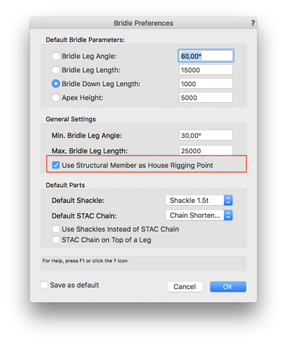
The Structural Member needs to be at the right elevation. Otherwise there is no connection possible.
Also make sure they are enabled in the Bridle Preferences.
If you still run into problems, can you please provide the a drawing?

-
1 hour ago, Martijn Wingelaar said:
I've started so redo all the steel length and chains.
I'll add my file.
I'm still working on it now I only got metric length.
Thanks for sharing.
-
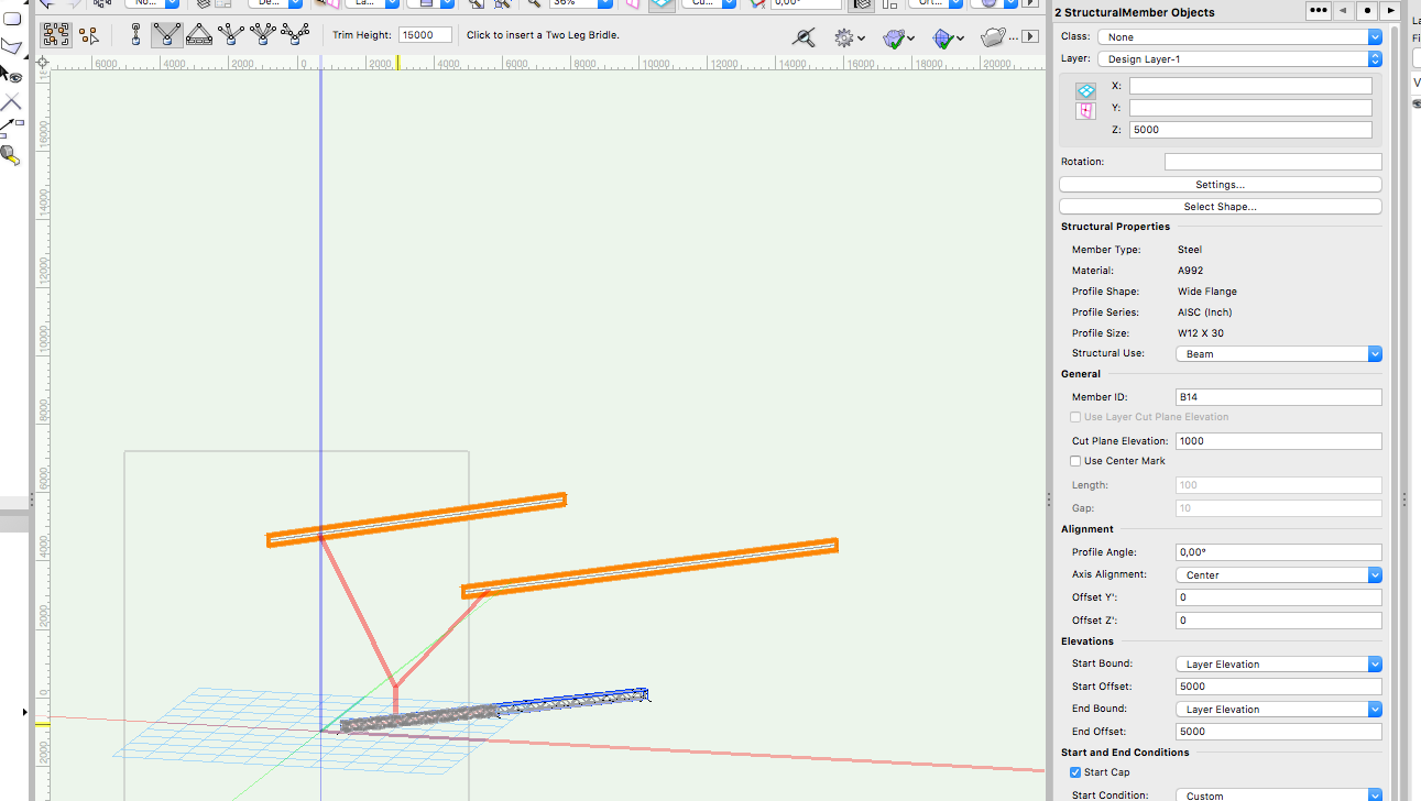
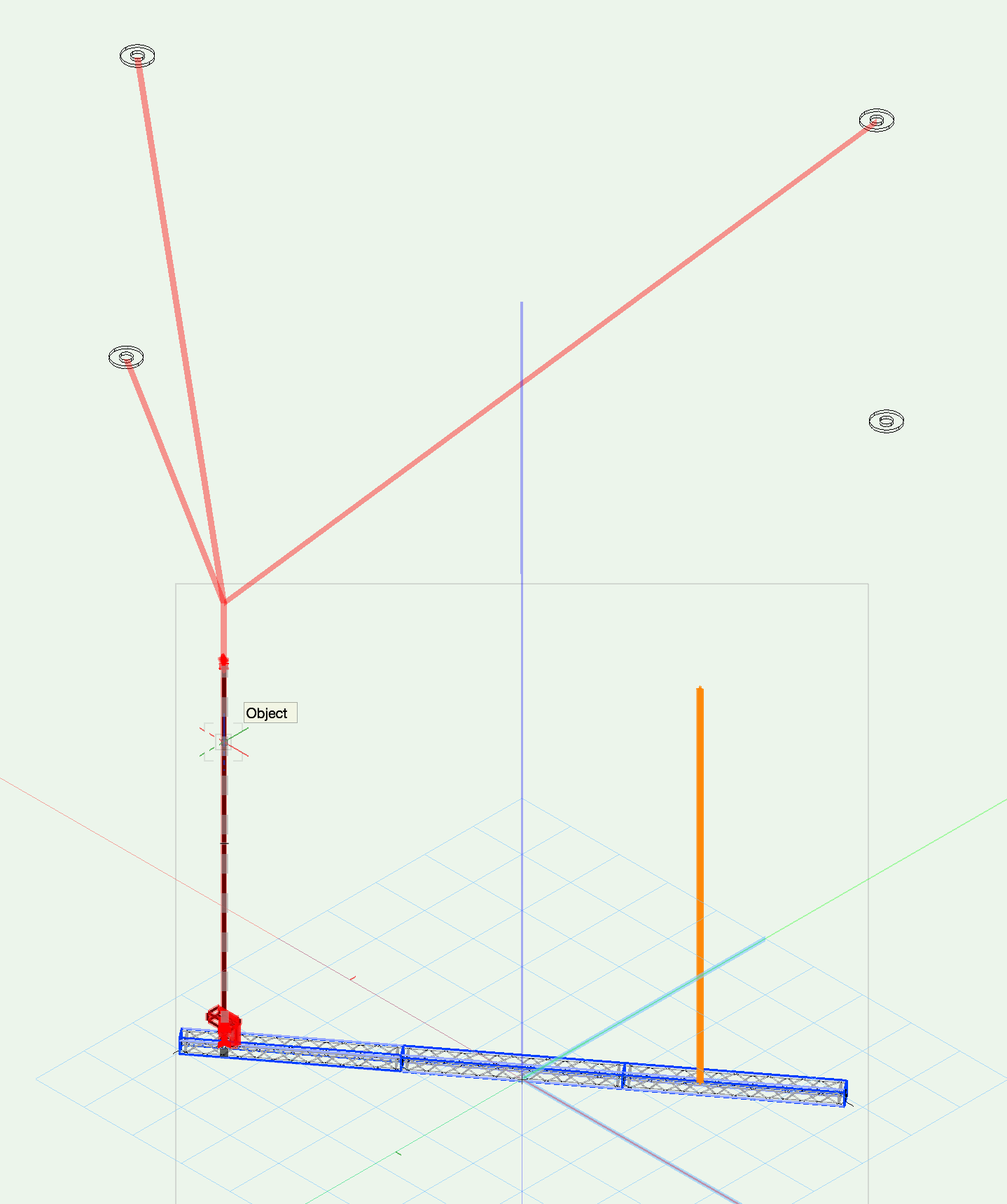
13 hours ago, Sebastiaan said:
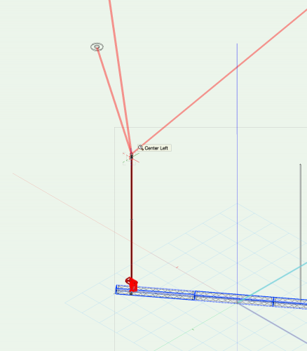
When I select the bridle downlength mode, then the tool makes a bridle all the way to Z=0. On each other mode I get a downleg that I don't want.
@SebastiaanYou also can modify the Bridle after insertion in the OIP for the Down Leg Length. Can you post a screenshot of what you try to use? I'm not quite sure.
13 hours ago, Sebastiaan said:Can I make anything work as a rigging beam as opposed to a rigging point? (the structural member tool does not work yet)
This should work. Make sure you insert the Structural Member at the right height.
13 hours ago, Sebastiaan said:If i make a simple two legged bridle the it always gives me a chain shorten on both legs. I should only need a chain shorten on one of the legs.
I will write this down. I think there is room for improvements there.
13 hours ago, Sebastiaan said:If I do line up a hoist to two rigging points, then I get odd Bridle lengths. Even with the maximum leg length set to 2000 Can I easily make the leg lengths of a bridle shorter? Changing things in de OIP breaks the bridle.
Can you send a screen shot?
-
thanks for your Feedback. I have added some information about your question. I hope you find them useful.
1 hour ago, Martijn Wingelaar said:Hello Users.
I've been trying the Bridle Tool.
But I think is a mess.
They tried to make something but didn't understand how.
1st The bridle doesn't snap to a hoist that's inserted with the Hoist Tool.
You can change the downleg for a hoist.
But what rigger start with designing bridles before you got a hoist.
This is possible. Just makle sure that the hoist chain in not to long. If this is the case you get an error.
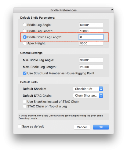
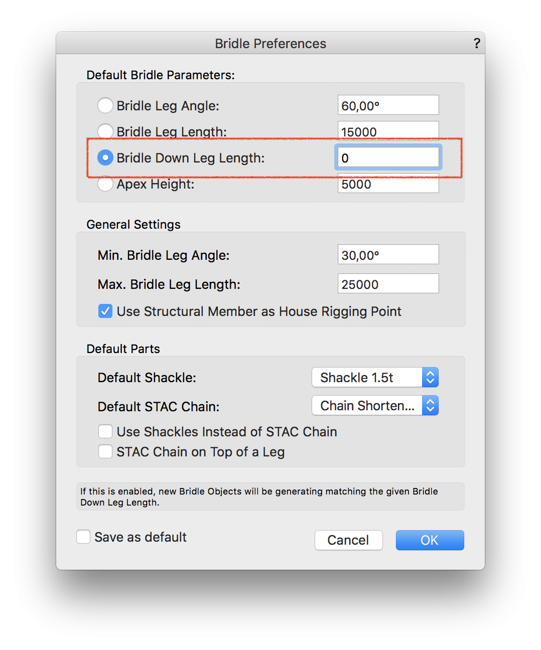
1 hour ago, Martijn Wingelaar said:2nd Why do is there always a downleg "what's called a drop or stinger in the business".
A downleg should be used if the hoist does not have enough chain length or you need a steel for a deadhang.
You can set the down leg length in the Bridle Peferences to 0.
 1 hour ago, Martijn Wingelaar said:
3th why is there a 4 leg bridle choice.
A 4 leg bride won't work cause there's always a leg who does nothing cause steelwirerope is never exactly on the mm.
There where several request for this. But I agree with you.
1 hour ago, Martijn Wingelaar said:4th They should change the trim height to apex height.
If the tool snaps to a house rigging point or structural member you don't need a trim height you need a apex height.
You can define the Apex Height in the Bridle Preferences.
1 hour ago, Martijn Wingelaar said:What I'm missing is the text from the bridle configuration in the drawing instead of the assembly diagram.
What do you mean with this?
1 hour ago, Martijn Wingelaar said:How is the rest thinking about this?
1 hour ago, Martijn Wingelaar said:Greetings Martijn.
-
@Projx_CACan you share the file with me? Then I can have a look on this issue.
-
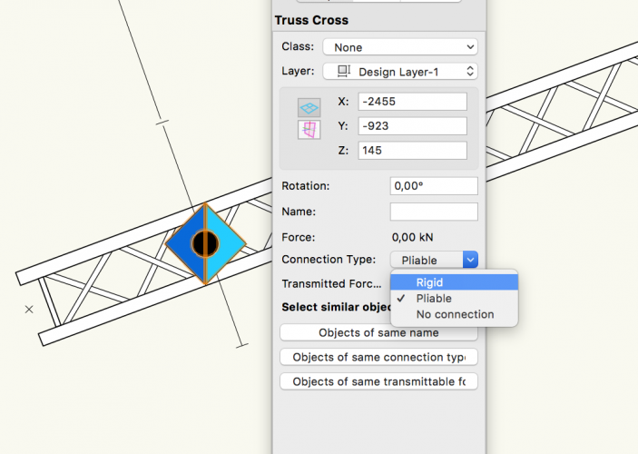
Hi,
you need to change the setting in the Truss Cross. See the attached screen shot. Rigid Truss Cross have a square center element, pliable have circles.
-
Hi Jim,
from your posting I assume that you are using the german Vectorworks?
In this case just update to SP2


Distributed Loads: Height differential
in Braceworks
Posted
I think that the issue comes from your drawing order / snapping of truss.
The first click (right part of the line load) did not snap to the truss. So it uses the elevation from the mouse click.
Your second click snapped, because of this now for the second point the high of the truss is used.