


Antoine D'Halluin
-
Posts
17 -
Joined
-
Last visited
Content Type
Profiles
Forums
Events
Articles
Marionette
Store
Posts posted by Antoine D'Halluin
-
-
Hello Pat, Hello everyone,
thanks for your fast answers.
12 hours ago, Pat Stanford said:Can you post a very simple file with three or four of the lighting devices and your sample worksheet above.
I would like to try something, but I don't want to have to make a test file that might not match your conditions.
Here is the original file ; I have deleted most design layers / sheet layers to make the file smaller so probably no totally relevant but I kept the needed layer for the sheet layer "Light2" that has this worksheet pasted on it
https://www.dropbox.com/s/gdfu3slr0az5y0t/VW fixture mode test file.vwx?dl=0
15 hours ago, Pat Stanford said:The thumbnail picks up the settings when the worksheet is recalculated.
You may have to turn off the classes of the label legend when you do the final recall of the worksheet for presentation.
Hopefully someone else has a better idea.
It seems you are right : looks kind of unpractical to hide/show labels everytime you edit/recalculate a worksheet... but at least it works...
Also noted your way to work @DCLD ; thanks for the idea ; still this is print/paste, not dynamic, all I hate to do on drawing as you always have something that change in fuutur & you are stuck...
Hopefully the re is a better way ?
thanks everyone & have a nice end of week
Antoine
-
Hi everyone,
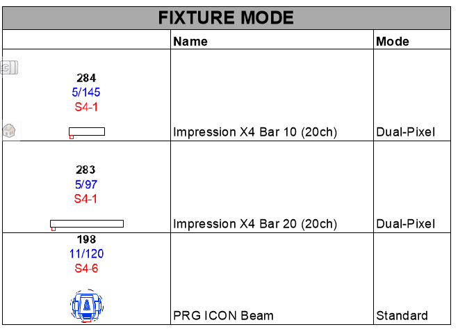
Trying to display on plots a complete fixture legend including fixture Mode. As I could not find how to insert on the instrument summary tool, I have created a worksheet listing fixtures & wanted to add fixture Image. Yet when displaying, I have the label legend visible on top of the fixture image... Is there a way to suppress & only have the default thumbnail or top view ?
Else maybe you use another way to display fixture mode on drawings ?
Thanks for your inputs !
Antoine
-
Hello guys,
sorry if this topic has been discussed, could not find any thread related
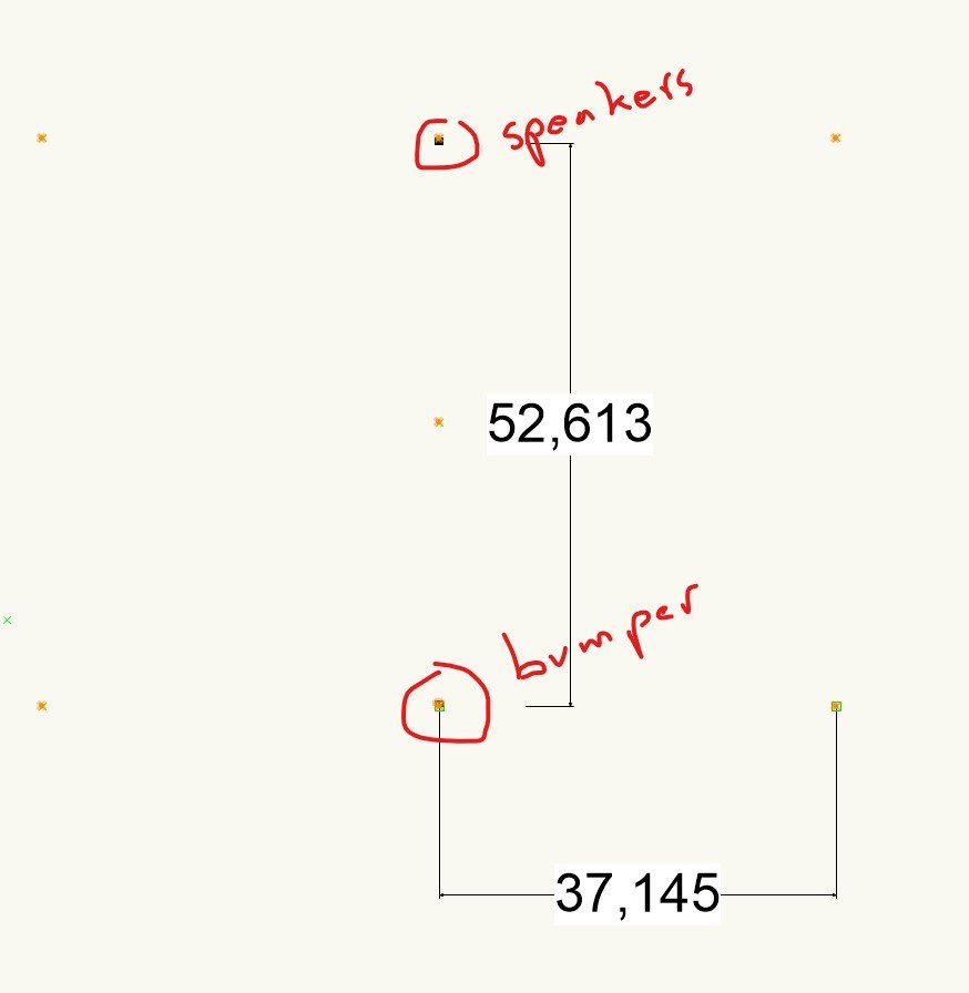
I have designed a speaker array based on symbols1. (Adamson S10) (VW21 SP4)
- first the position of rigging guides are very far from insertion point (50m / 37m) ; is it something I have to configure ? ; I don't really need them yet it seem this impact my following question
- The bumper is inserted at the insertion point ; but the speakers are populated at the opposite rigging guide point... Is it a library problem ?
- I have tested with the L acoustics KAra & bump ; both populate at the proper position (insertion point -yet I still have these very far rigging guide points that looks strange
thanks for your comments & suggestions
Antoine
-
Hi gentlemen,
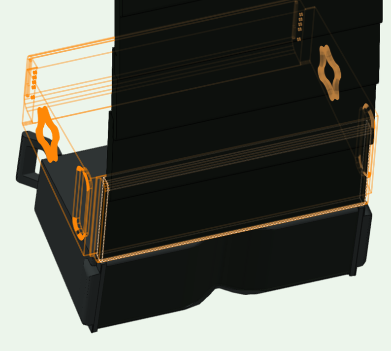
same issue here with Adamson S10 symbol (bottom is L acoustics Kara to compare/test).
@JustinVH : How can we track if this bug is under study or solved ? or if there are any workaround ?
I have searched for "VB-177498 - Invisible geometry in some Resources" but could not find ; where should I look ?
thanks in advance
Antoine
-
Hi Greg, hi Tom,
Just to give you some insight as this is an old topic for me, L Acoustics does not permit export of their speaker set-up as they are afraid people could collect their venue database drawing (stupid reason IMHO...) so no export in any format...
Maybe if contacting them on behalf of VWX they might be more open to share ; yet even contacting under name of one of worldwide leader of AV supplier they did not want to change their position...
Yet I believ the connection between VWX and sound design software is key for futu and effciciency ; there is no chance we will ever avoid the simulation and design in manufacturer sooftware ; then import into VW of initial versions and then updates is always a waste of taime and a pain as it brakes links, change weights & riggin links ; presentations etc.
So this would be a nice improvment for VW soft to be better connected to sound software , on the same mindset of GDTF with lights.
@Tom : If this integration topic could be considered in your dvpt journey, Adamson migh be a good first step/demonstrator toward other manufacturer as their soft already export setup into dwg ; Yet with better interconnection we would prefer to keep speakers as speakers/clusters and not dwg objects. If there is any interest from your side, I would be happy to connect you to support connection to Adamson lead dvpt team.
Antoine
-
oops ! I update my signature.
thanks for this careful attention 😉
-
Thanks Rob & Justin, for your follow up & feed-back
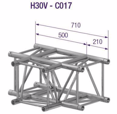
I have checked on the Prolyte Website & actually their dwg is 713mm ; as you said. in other direction half is 356,5 so same calculation hypothesis...
So I feel like the issues is coming from their side. I will try to discuss this subject next time with our Prolyte interlocutor ; I cannot imagine having all corner library in 2 versions to manage connectivity in Bracework....
-
Yes but this generate a big problem when you design a large closed set-up of truss.
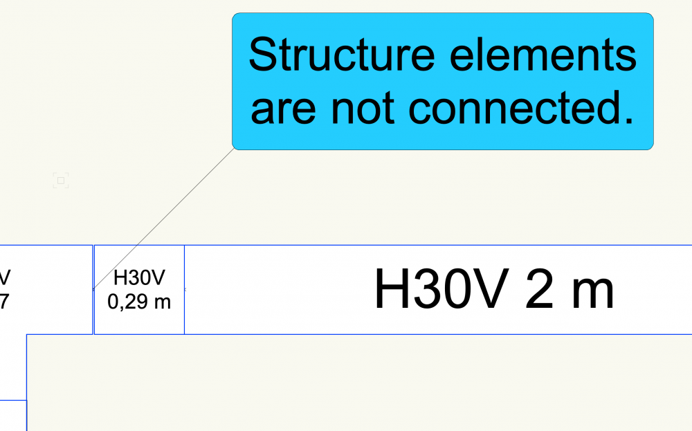
On paper/software, you cannot connect together the trusses and so you cannot do a bracework calculation.
In reality, the metal is a little flexible & the concept of pin & clip is specially designed to compensate this metal tolerance.
So I would highly recommend to stick to the official size of the truss that allow connexion of closed system... if not Bracework does not work...
-
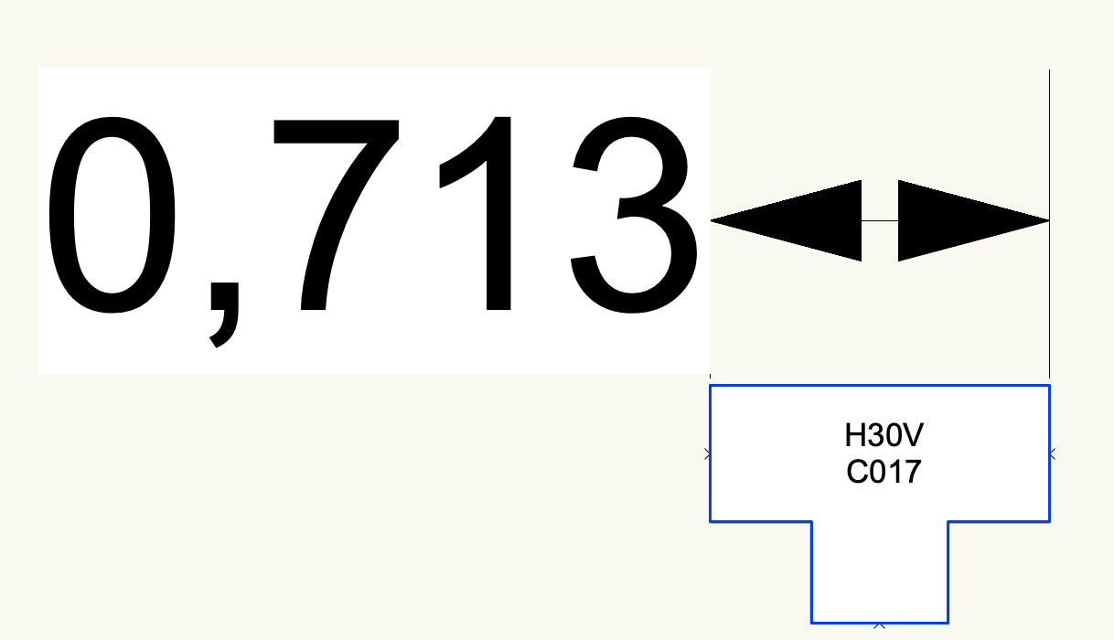
Hello,
I spent the night trying to solve bracework connection issues between trusses on a big truss with many corners & finally I measured several Prolyte H30V corners (C017, C016...) & found 0,713m while on Prolyte dwg symbole they measure 0,71m.
Am I doing a mistake or is there an error in VectorWorks Library ?
thanks


-
 1
1
-
-
Hello Brandon,
thanks for your answer & video.
yes I am exactly trying to connect with a hoist or dead hang as first exemple. first try is ok ; but if I have previously linked trusses, I cannot re-link them again.
see video below
-
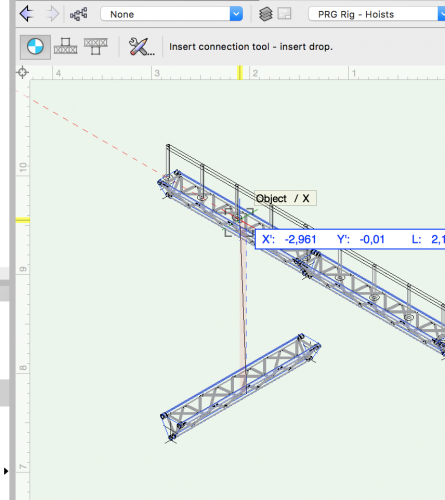
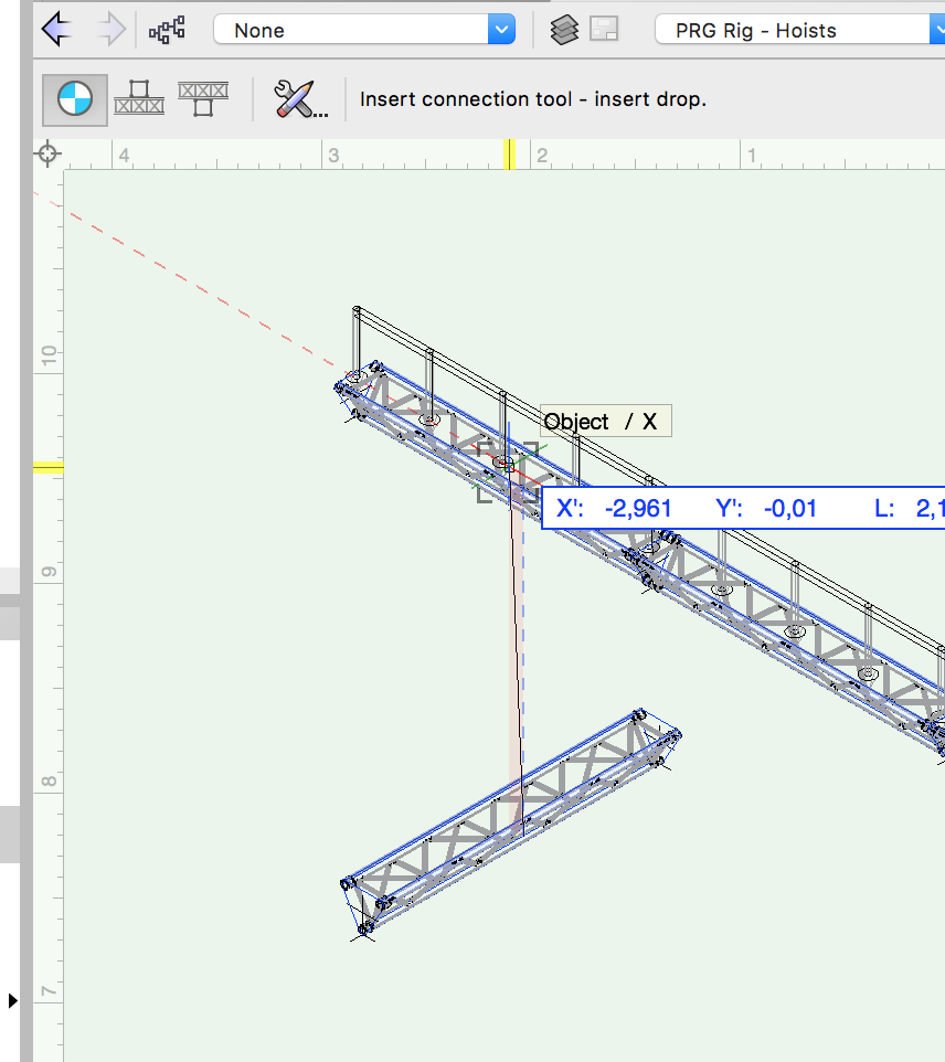
Hello,
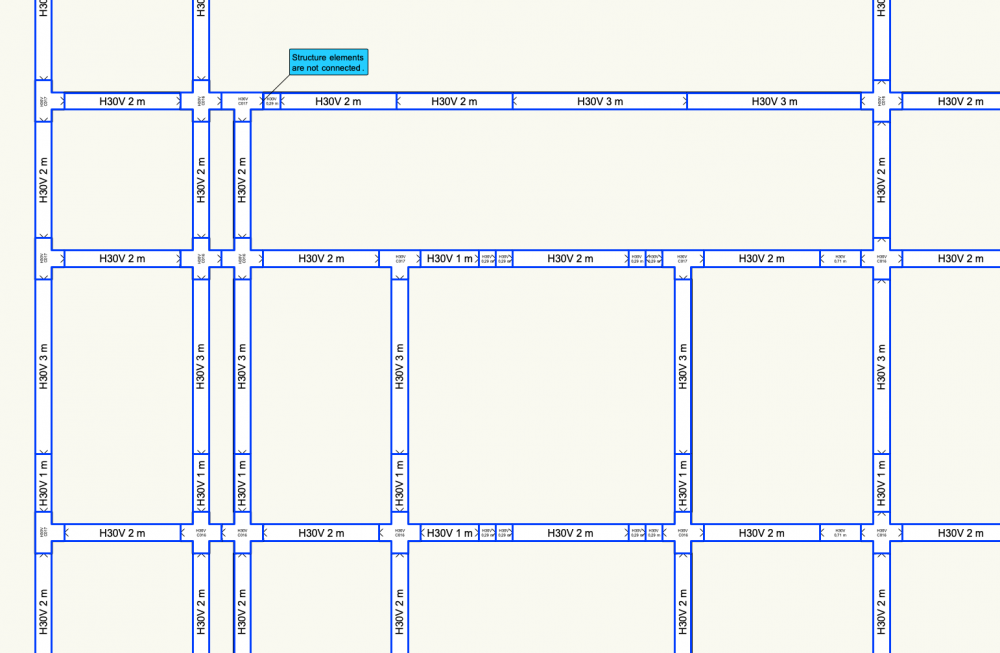
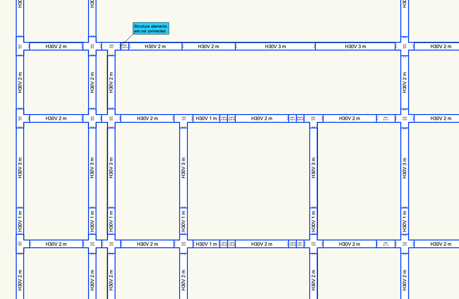
I have strange behaviour when trying to connect 2 trusses with dead hang or hoist :
If I plot on true at 10m, another at 8m rotated 90° ; I can select insert connection tool ; select one truss & then the other one. Then, the 2 trusses or connected. ==> OK
If I suppress the hoist or the dead hang (with "suppr" or "<--" keyboard key) ; I reselect the connection tool ; I can select any of the trusses for first connexion but when tool activated & link to first one, I cannot click on second truss ; it never switch to "red select" status (see picture enclosed). So I can never reconnect the 2 trusses. As if a connexion was still existing...
I am using the wrong way the tool ? Do I have to reset something ? purge physical connexion somewhere ?
I showed to several colleague ; none of them ever experienced that...
Should I reinstall VW ?
thanks for advices
-
Hello guys,
does one of you have Prolyte S52F Library ? Is this trusses to be included in next release or service select library ?
Same question for Prolyte ST Towers ; there is only one top part of the ST towers in the Prolyte => Accessories => Prolyte MPT => ST Tower (very surprising to put ST parts into the MPT Folder !!! makes no sense !! developper probably does not know what it is...). I need the full tower...
why an "MPT Tower" folder with inside, all the 30/40 truss bases ? no link with MPT towers... maybe a new adapted name would be easier to understand
thanks for your answers & update in next versions
-
Thanks JimW it works !
;-)
-
1
-
-
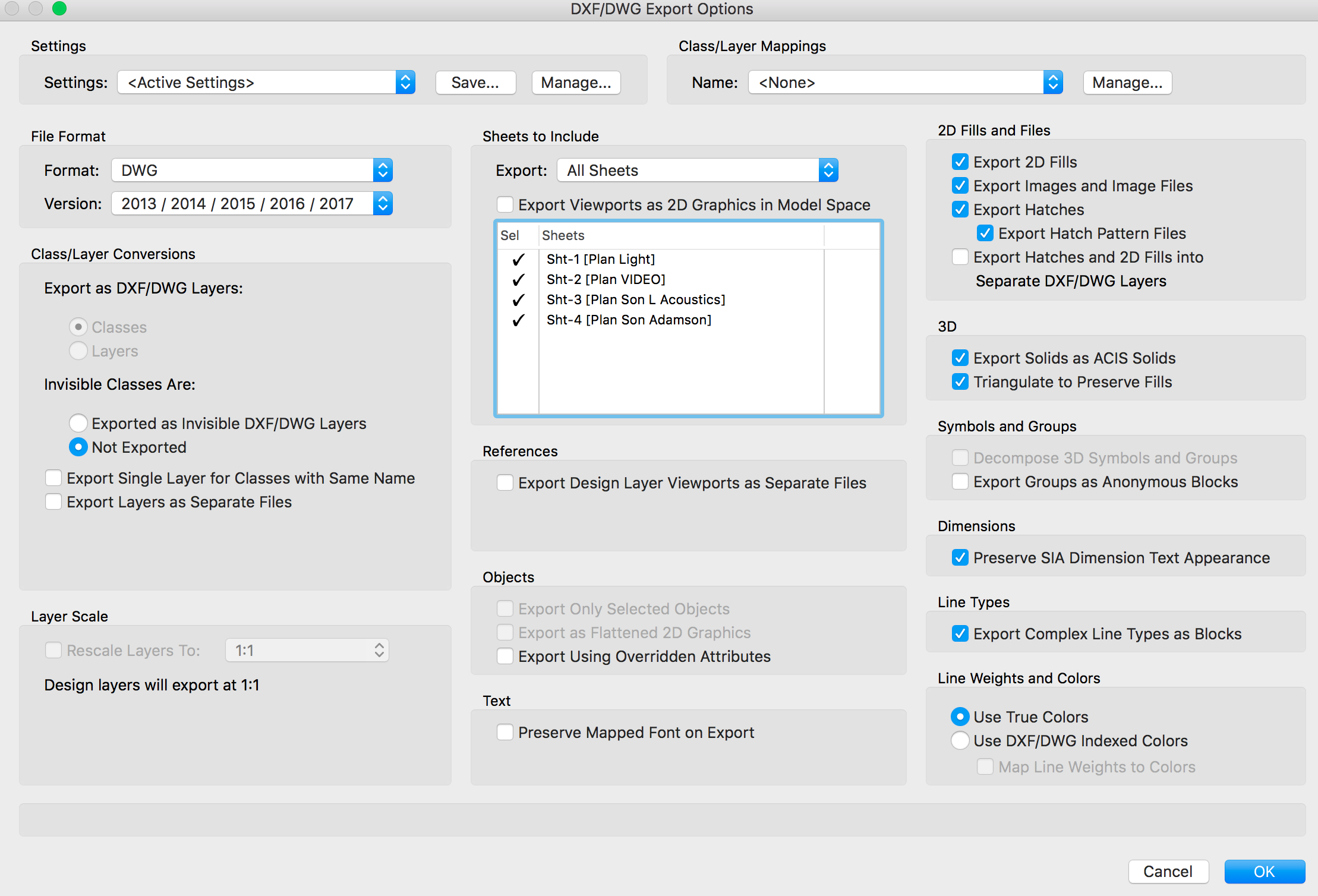
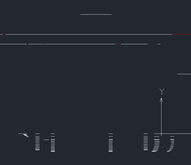
Hello Guys,
I have the same problem, when exporting in DWG, everything is flat. every item is correctly positionnated in 3D but every item is in 2D.
I have tested to export when being in a 3D view or a 2D plot view but it does not change anything.
Is my export config not ok ? (see picture below). this is the very first time I see it ; is it a new functionality from VW2017 ?
thanks
Tocsin
-
Hello,
thanks for your answers. No, resizing the width did not make the other element to reappear. even playing with top and lower limit doesn't make all visible
after checking a lot of element, I finally joined the palette to another palette and then, I got top bar reappear (the one with the expand and the close button) & the palette to resize.
I cannot replicate the bug & I don't know really what I did to get in this situation sorry. but I can note some parameters of my config if it helps to replicate... let me know
kind regards
-
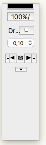
Hello,
when I resize the attribute palette ; it crop a part of the palette simultaneously as it resize the text and the boxes (seems to be proportional). then you have no access to the hidden part of the palette. I cannot scroll up or down.
for example, I have reduced the size of the palette from the top ; then it has cropped a part of the top. and then I tried to increase the lowest part ; it just generated some white part bellow the palette. see picture joined.
Is it linked to my config ? to Mac Os config ? to some config error in my VW config ?
thanks
PS I am using VW2017 on Mac OS 10.11.6.

Supress legend label on Worksheet Image
in Entertainment
Posted
Hello @Pat Stanford,
sorry that the link does not work... suprising... here is a new try : https://www.dropbox.com/s/ziemi1lrrqi1cbd/VW fixture mode test file.vwx?dl=0
thanks in advance for your suggestions
kind regards
Antoine