
KroVex
-
Posts
29 -
Joined
-
Last visited
Content Type
Profiles
Forums
Events
Articles
Marionette
Store
Everything posted by KroVex
-
Hello Sebatain, The node "Infinite Intersect" is originally designed only to determine the intersections of two lines, or between multiple lines in one input and one line in the other input. It thus requires an iteration to allow this over multiple lines. In the attached document, I have modified the "Infinite Intersect" node and added two nodes from DomC, "Items to List". Now the script works as desired: Points on Poly 240409.vwx Best regards, KroVex
-
I have found two ways to solve my problem. Path 1: I execute the command "vs.DSelectAll" before the menu command and then use the menu command with SEL=TRUE - which is somewhat cumbersome. Path 2: Instead of the menu command, I have created a Marionette object from all symbols, with which I can directly switch the views. I have now decided to go with this path...
-
Hello Antonio, just to make sure I understand you correctly, the following procedure is not possible: Manually activate three symbols in the plan -> Execute menu command -> receive the symbol names of the currently activated symbols? Even if I additionally filter the objects by the active layer, the problem remains with SEL=TRUE that too many objects are outputted, for example, if anything was once selected in another group on this layer...
-
Thank you for your reply, but the Marionette script is intended as a menu command, not as a Marionette object. Simply put, the menu command retrieves the symbol names and positions of the activated objects and places new symbols on the plan accordingly. Sorry if this was not clear. Regards KroVex
-
Hi all, I have created a Marionette menu command which, from selected floor plan symbols in the plan, is supposed to place view symbols at an X distance defined via dialog. The problem is that using Objs by Crit with VSEL=TRUE does not output any objects. However, if I use SEL=TRUE, objects are outputted, but far too many, since selected objects that are not visible (e.g., selected objects in groups and symbols) are also captured. What am I doing wrong or what have I overlooked? Attached is the document with VSEL and SEL: SelectedSymbol.vwx Regards KroVex
-
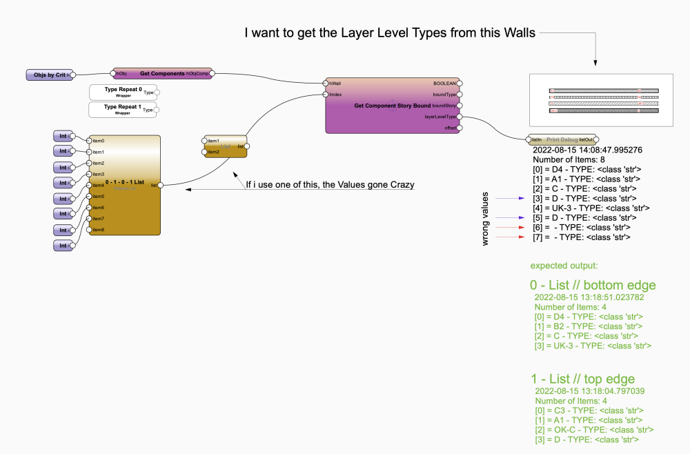
Hi All I'm trying to build a Wall Merger Tool (separate Walls are combined to one Wallstyle). Im almost done, but one last thing make me crazy: With vs.GetObjStoryBound i can get the Layer Level Types. It needs as input the component handler and the boundID. The boundID needs a 0 for the lower edge and a 1 for the upper edge. So if I feed in a list of 1's, or a list of 0's, I get all top edges or all bottom edges extracted. But when I shuffle the lists (no matter how), wrong values come out: GetLayerLevelType.vwx Sure, I could use "Get Component Story Bound" twice, once with 0 lists and once with 1 lists. But I'm interested in why it doesn't go together and it wouldn't be solved that nicely either. Does anyone have an idea or explanation? Greetings KroVex
-
Hi All I have the same problem and can't switch to VW22 for a while.. Simple Testbuild: Testfile: ControlPoint.vwx Is there a solution for VW21? Greetings KroVex

-
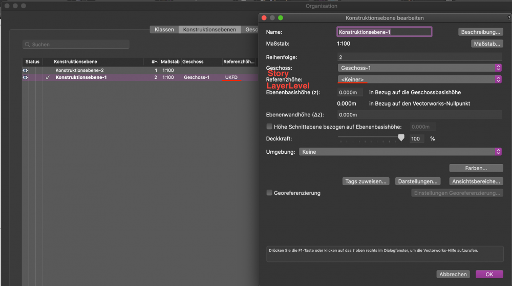
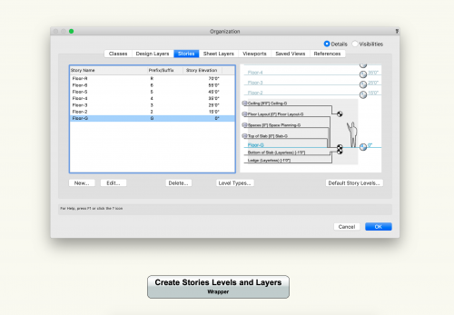
Hi All Inspired by this Network created by @sbarrett, I would like to create new Story's, but without creating new layers. To do this, however, the Story should be linked to the existing layer. The Dev-Wiki says that with the command "vs.CreateStoryLayerTemplate" the creation of a new layer is optional. However, if no layers are created, I need the command "vs. AssociateLayerWithStory" so that the story is linked to the layer. So that "vs. AssociateLayerWithStory" works, "vs. SetLayerLevelType" is also required (according to the Wiki), but this creates a new LayerLevelType (without elevation o.O) and I can't use the existing LayerLevelType from the Node "Create Default Story Level". It is also strange that in the organization I see the additionally created LayerLevelType at the Layer, but as soon as I edit it, it is not assigned to any one: What am I doing wrong? Or have I misinterpreted the procedure? File with the new Node: Story.vwx Greetings KroVex PS: I hope the translation is not too bad and you understand what I mean. 🙈
-
 Hi @sbarrett Thank you for this great Script 👍 However, I noticed that the wall height is not adopted: ("Ebenenwandhöhe" = Wall height) Do you know what that could be? Tested in VW 2020 SP4 (550627) and VW 2019 SP6 (522773). Greetings KroVex
 -
 Hi All I have some marionette network saved as a symbol in the resource manager. But even when it's not placed in the drawing, and I import a DWG or just update "intelligent objects" (by the menu command), the marionette network will be triggered and give some error messages (which is logical because no data has been entered to the Marionette Object). But why? Is there a way for the Network only to be triggered when it's placed in the drawing? greets KroVex
 -
Thank you Marissa for the detailed explanation. Then I hope that the priority of the bug is big enough, that it will be fixed soon 😀 Greetings KroVex
-
Hi All Simple Question: Why does the plan turn to 0 ° when running a Marionette? When executing a vector script or Python script this does not happen... We work a lot with rotated Plan's, and this effect isn't so cool. Greetings KroVex
-
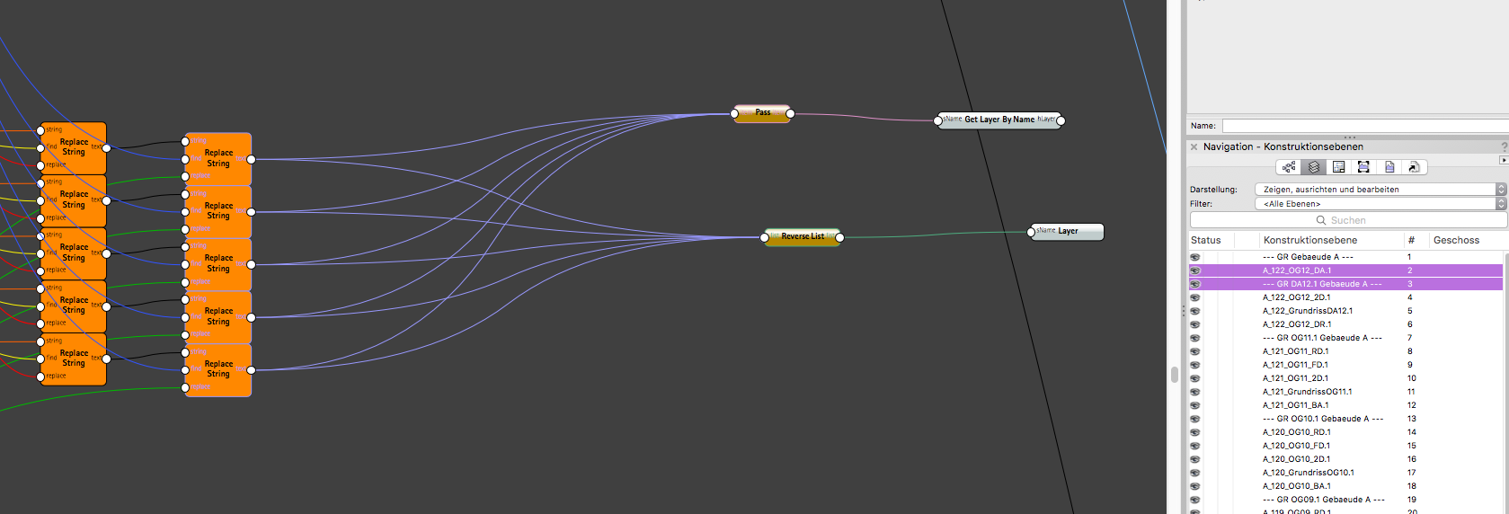
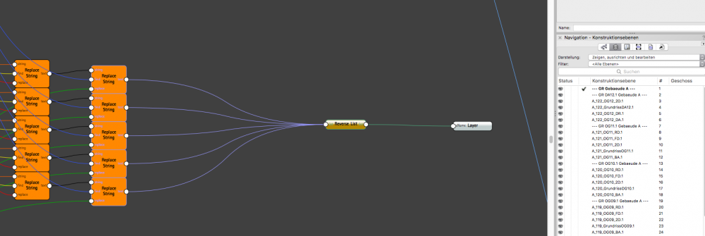
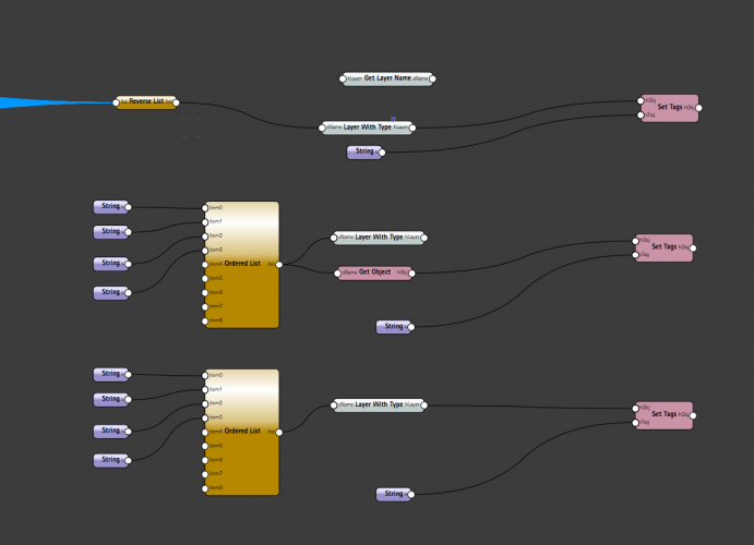
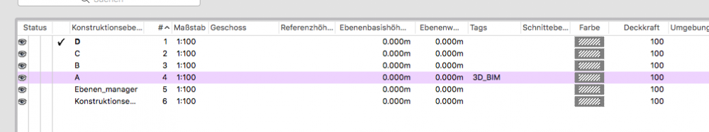
Hi All I have a question about the Layer Order, when i use "Layer with Type" or "Layer". I have textfields wich i manipulate with some "String replacer" before it reverse the list* and create Layers. The Order of the Layers are in the correct range then. But if i only add some new Nodes, which have nothing to do with the create layer section, the Order will change. I have no idea what affects the layer order. It seems to me completely arbitrary. *I need the reverse node - without it, the order mess is way larger. How can I determine and influence the order? Greetings KroVex

-
Hi All I have e question about to add Tag's to Layer: I have a Marionette-Network which creates several design layers at once. So the output is a list which ends in the node "Layer with Type". Now, if I use Marissa's Node (Set Tags) to add tags to the layers, then only one layer will be tagged. Does anyone know what I'm doing wrong? I have tried several ways: Result: File: Tags_to_Designlayer_List.vwx Greeting KroVex
-
Hey @Nikolay Zhelyazkov Thanks for your File. I could find the mistake. The nodes "Set Record Field" and "Get Record Field" come from a VW2018 file and do not work anymore after migrating. When I use yours, or new nodes, it works. 🙄 Greetings KroVex
-
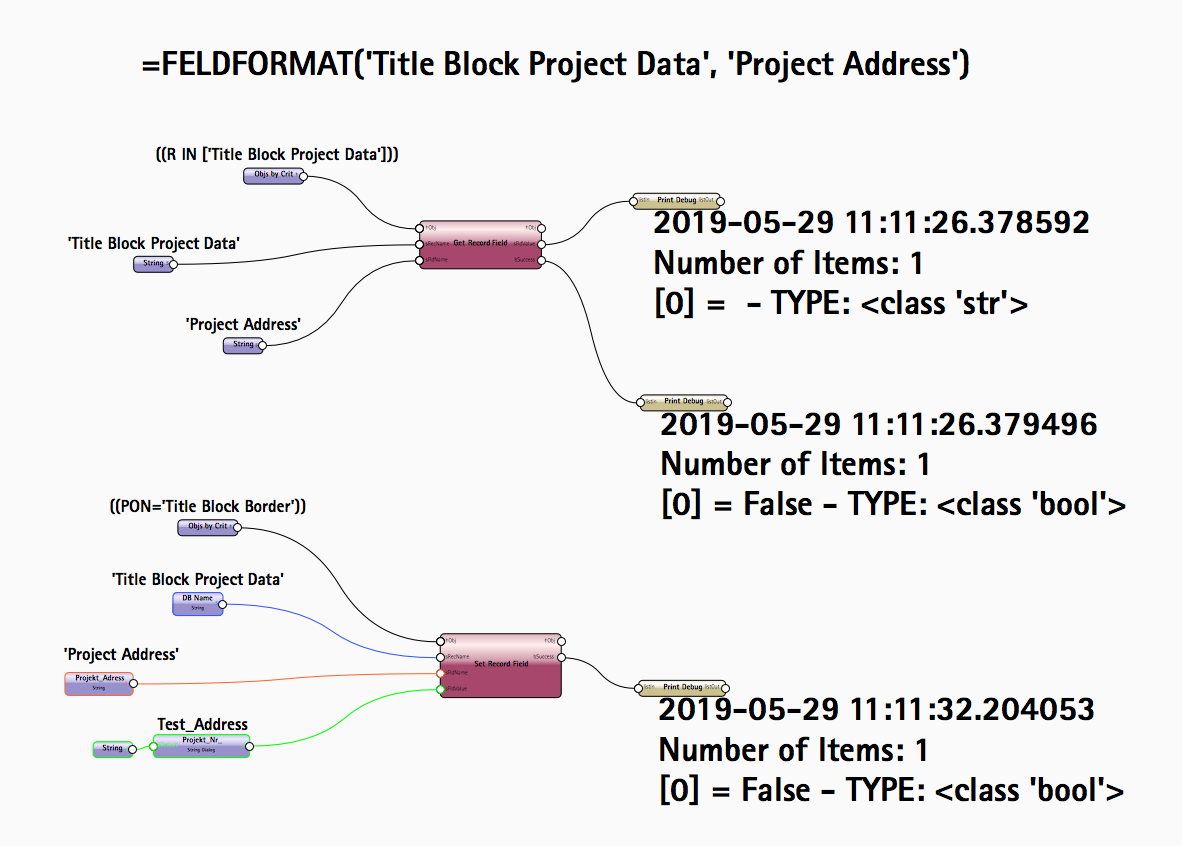
Hey All I want to ask, if it impossible to read or write to/from the Title Block - Database? I have try it like this: But it didn't work... Did i do something wrong or it is impossible? Greetings KroVex

-
That's wonderful, thanks Marissa. 🤩 It looks understandable, I'll test it 🙂 Greetings KroVex
-
The Vale-Node Works fine, thx. Another Question: Since Vectorworks 2019 you can assign tag's to classes. Are these Tag's Class attributes? Or how can I add Tag's to Classes with Marionette? Greetings KroVex
-
Thank you a lot, I'll try it with the valve node. Greetings KroVex
-
Hi all I have two questions about Marionette: 1. Is there a way that only an alert dialog appears when a "true" or "false" arrives the Input from the alert dialog-node? 2. I have made e specific Class-Generator. Is it possible to generate an attribute popup, which allows me to choose the fill color and pen color/thickness in the OIP? Greetings KroVex
-
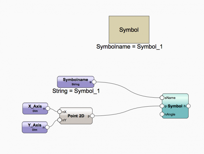
Hi halfcouple Thats not so Complex: 1. 2. Right-Click on a Node -> Wrap to Marionette Network* -> Right-Click to the Wrap-Node -> Convert to Object Node* (If you give the nodes a name, they will appear in the OIP (e.g. "X_Axis")) *Or a similar command name (have only the German VW version). Greetings KroVex

-
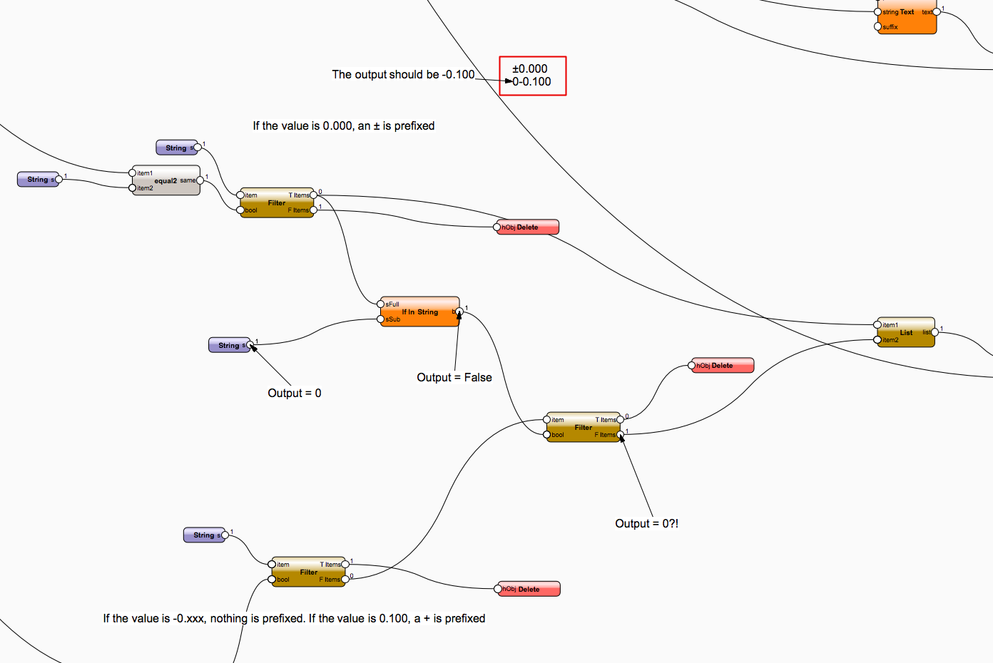
Hi There I have a Question about the "If in String Node": The following circuit should me depending on the value, set a prefix, or not. However, the "If in String" not only outputs False / True, but also the sSub input string. How can I prevent that? Wohnung_marionette.vwx Greeting KroVex

-
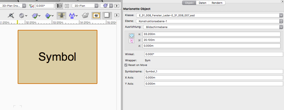
Hi All With your help, I was able to finish the tool. In our project we need the absolute sea level to control the component heights. The red cone is placed on the object to be measured and the text indicates the sea level. In the OIP it can be specified on how many meters the project height (0.00m = 550 meters above sea level) is. The display is updated via the Actualize button or move the text. You could certainly optimize the tool, if you somehow manage to connect the text with the object. But for us it is enough as it is. Greets KroVex Meter_ueber_Meer_Marionette.vwx
-
@Marissa Farrell Thank you a lot for this great Node Idea. It works perfectly 🤩 I need it to show the sea level in relation to the building. When it's completely finished, I'll share it here. 😊 KroVex
-
Hey Marissa The Node is from the 2018 Version, but i have change the botZ = zValue-depth/2 to botZ = zValue, because the value was never right without this change..