
Taproot
-
Posts
516 -
Joined
-
Last visited
Content Type
Profiles
Forums
Events
Articles
Marionette
Store
Everything posted by Taproot
-

Viewports disappear and move around the sheet
Taproot replied to Taproot's question in Troubleshooting
Hello Adam, OK - I've made the change and will let you know if the problem reappears. -
I find that texture application is buggy ... (I seem to be saying that about a lot of things lately). Often you need to change the texture to something else and then back to the original to force the redraw / remap of the object.
-
Viewports disappear and move around the sheet
Taproot replied to Taproot's question in Troubleshooting
Has this item been added to the bug list? It's still a daily nuisance. -
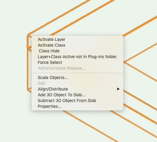
Yes, it can be done. I'm not sure about v.2015, but it certainly can be done in today's version. Here's a link to the help page: http://app-help.vectorworks.net/2016/eng/VW2016_Guide/Floors_slabs/Editing_Slab_Geometry.htm Here's how: Draw the slab and then draw an extrude along path for the geometry of the turn down footing. Select both and right click to pull up the context menu. Select: "Add 3D object to Slab" and voila, the slab is now modified to contain the added geometry.


-
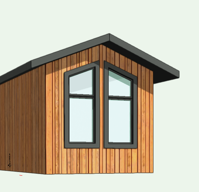
Yes, you can do this (and it's easiest if you have the four windows modeled separately). In the OIP, experiment with the "Top Shape" set to "Sloped" and fiddle with the "Rise" amount to get the correct pitch. In your case, where you have two bands of windows atop one another, you can also experiment with the "Transom" setting to closely approximate the upper window lites.

-
Airtable has a whole list of templates that you can access. Here's a link to the 'Real Estate' section: https://airtable.com/universe/category/real-estate They are good for seeing what is possible, but once you get the hang of it, building a customized database that fits your needs is REALLY fast.
-
It sounds like you are either drawing sections or details in 2D - Yes? We don't use the linear material tool for the reasons that you have found as well as it's reasonably small range of functions. Instead, try using the wall tool. That will allow you to set a single component or a series of components and will display correctly regardless of the angle that you draw them at. For items like corrugated roof decks I would suggest creating a custom line with a repeating pattern that matches the deck profile that you want.
-
It turns out that Patrick McConnell is the author of the Super Leader tool and gave his blessing to share it here. If you haven't used it, give it a try... you might find it useful. Super Leader.vso
-
"Super Leader" is a user scripted tool (formerly available for a small fee from VectorDepot). We still use it instead of the built-in leader tool. It offers more control, arrow styles ... and yes, it auto-classes the leader and arrowhead separately for consistent display. I'll send a note to Patrick McConnell to see if there is a way to make it available for newer users to access.
-
Viewports disappear and move around the sheet
Taproot replied to Taproot's question in Troubleshooting
I am curious if in the end that strategy works. I can see the logic in trying to keep the file lean so that fewer legacy items can cause problems. For our workflow, we've taken the opposite approach. With the exception of memory intensive libraries (symbols & textures), we keep most everything in our template file. It means that a "blank" file is about 75mb and a project file is routinely around 250mb in size. But so far we haven't run into much in the way of memory challenges. Having everything in the template: Sheets, Schedules, General Notes, Keys, Standard Symbols, Section Viewports (with standard annotation), etc... saves us a lot of time in recreating or importing these items and helps to ensure a standard across the office. It also makes it easier for us to update our standards as most everything is predominantly in one place. It's great that all of us are experimenting with different approaches so that collectively we can get a better sense of what works and what doesn't. -
Viewports disappear and move around the sheet
Taproot replied to Taproot's question in Troubleshooting
HI Boh, Yes, this file is one that was started in 2018 and then migrated to 2019. I'm curious to hear if creating a new template works for you, so if you go that route, let us know if that solves the problem. We've been steadily building our template file over the last decade, so I"m loathe to try and recreate everything unless its absolutely necessary. -
We're using the latest service pack for VW Designer 2019 and we're still getting this wacky behavior with viewports (see attached video). Viewports disappear and migrate all over the page. Once manually updated, they snap back to their correct position and visibility. It's a chronic problem, so we often have to refresh viewports every time we visit a sheet to see their content. Incidentally, I just learned that the latest Mac OS (Mojave) now has screen video capture (Command-shift-5) ... which might be helpful to others in communicating issues illustrated through animation. Screen Recording 2019-07-09 at 3.53.56 PM.mov
-
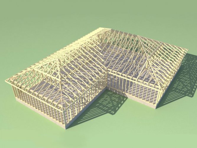
Here's a link to a plugin that is being developed for sketchup that gives extensive control of framing members. It would be great to see the framing tools in VW correct the numerous legacy bugs and take a leap forward.
-
Boh - that was helpful. I was able to reach Dan Belfiori (the author) via email and he gave his blessing to share the tool here. See attached. McBreaker_v1.vso
-
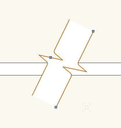
We use the "Breaker_v1" custom tool instead of the built-in VW breakline tool. I think it is superior. It allows for double breaks and uses a fill between the breaks to look correct. I can't remember if it is a paid plugin or free ... or even where I got it. If anyone else can remember where it came from, let me know .... if it's free, I would be happy to post it here. Icon:

-
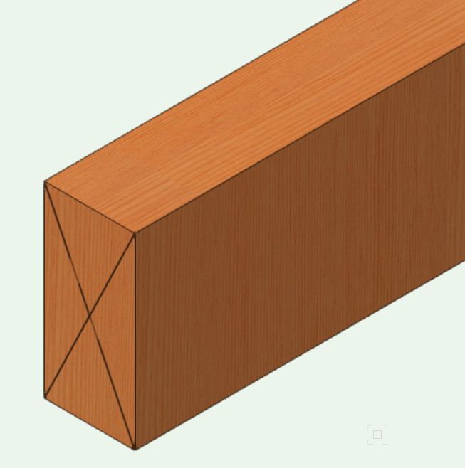
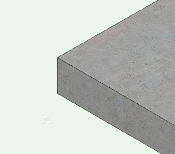
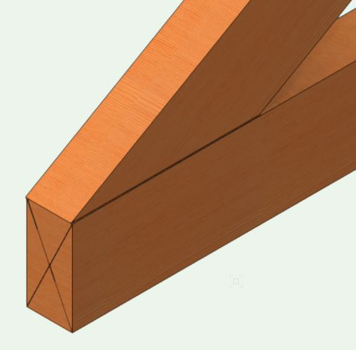
I have had issues with this as well. For framing members, textures map inconsistently. My solution has been to create a texture with a very fine grain pattern. That way, when it maps, if it is going the wrong way it isn't glaringly obvious. Here's an example. You'll see the top texture is mapped correctly, but the side texture is rotated 90 degrees. At most normal scales, this fact pretty much disappears. You'll see that we also use an "X" polygon for our custom profiles. That way, framing members appear correct in section cuts. The other trick that I use (when correct orientation matters) is to have two copies of my wood texture in each file. One texture is rotated 90 degrees from the other i.e. Wood Grain-Horizontal and Wood Grain-Vertical That way, I can quickly substitute the better looking texture for the face that is primarily viewed. Fundamentally, this seems like a bug - as the texture direction should be consistent on the sides of the member (rather than rotated 90 degrees from surface to surface).

-
Great! I'll review that information. Thanks.
-
Hi Marissa, Very helpful! Yes, I think the Marionette Object is the direction that I would like to take this. Can you point me to the examples or resources that I would need to learn how to do this?
-
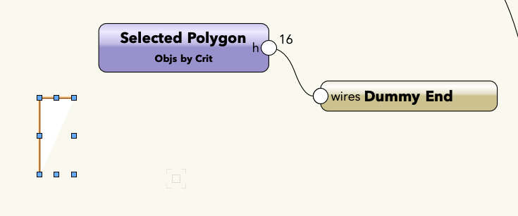
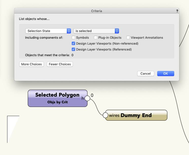
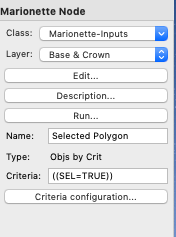
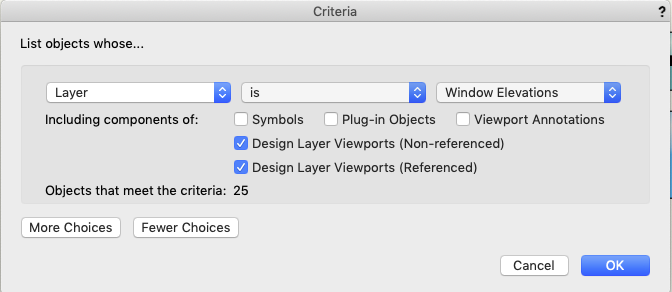
Wow - that is very helpful and it worked! I used single quotes to bracket the output, but does it matter if I use single or double quotes ... or does it achieve the same result? Marissa and Sarah each recommended one or the other. And Antonio, I didn't even know that was possible, so I'll use that somewhere further in my development. There is definitely a learning curve! My next endeavor is to assign a path for the profile. Currently, it is set up to a named object. My plan was to just draw a polygon and then have it selected when I ran the script. My first attempt crashed VW. So, I learned to use the debug mode - glad you included that! A little more help would be wonderful ... as I think I'm starting to get the hang of it. In order to use a selected object for input, I used the 'Object by Criteria' node. Here is how I set it up: And here it is in the OIP. It looks like the criteria is set correctly. When I run the script in debug mode... 16 objects show up in the debug output wire, while only one is selected. I can guess that this is BAD... so I checked the criteria again... And discovered that it had reverted to a default: Here the objects say "25" (not "16") so I assume this is just the default setting for Criteria and that the Criteria set in the OIP is still active ... but I can't fathom how with one object selected I got a result of 16. So I tried replacing the criteria with "Visible Selection State" and then reran the script. This time I received 0 in the ouptut wire. Sorry to ramble at length, just thinking that this step by step might help other users who are struggling with the same issues. Can you tell me what I'm doing wrong - or help me understand how I can best use an existing polygon as the source geometry via selection rather than needing to manually enter a name for it each time? Thanks.


-
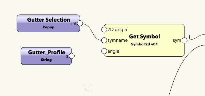
I'm new to Marionette and after going through all of the tutorials, I thought that I would start off by trying to customize Alan Woodwell's gutter script. That network starts with a 'String Input' which is then applied to a 'Get Symbol' using the "symname" node connection. My goal is to instead use a pop-up menu that includes all of my pre-selected symbols for ease of use. After reviewing the pop-up threads etc... I've figured out how to customize the number and name of options, but it appears that the output from this node is an integer rather than a string. As such, I can't just connect the 'Popup' node to the 'Get Symbol' node. How should I go about doing this? Here's a copy of the script (so far): @Marionette.NodeDefinition class Params(metaclass = Marionette.OrderedClass): this = Marionette.Node( 'Popup' ) this.SetDescription('This node demonstrates the use of a Popup OIP control. The values returned by this node will be integers based on your selection starting with 0 for the first option and increasing by 1 for consecutive options.') input = Marionette.OIPControl( 'Popup', Marionette.WidgetType.Popup, 0, ['Half-Round 4', 'Half-Round 5', 'K Style 4', 'K Style 5']) input.SetDescription('an OIP control representing the options designated within the script editor') output = Marionette.PortOut('int') output.SetDescription('an integer corresponding with the option selected in the OIP. Returned values range from 0 to one less than the number of options.') def RunNode(self): input = self.Params.input.value if input == 0: self.Params.output.value = HR4 if input == 1: self.Params.output.value = HR5 if input == 2: self.Params.output.value = K4 if input == 3: self.Params.output.value = K5 Thanks for your help.
-
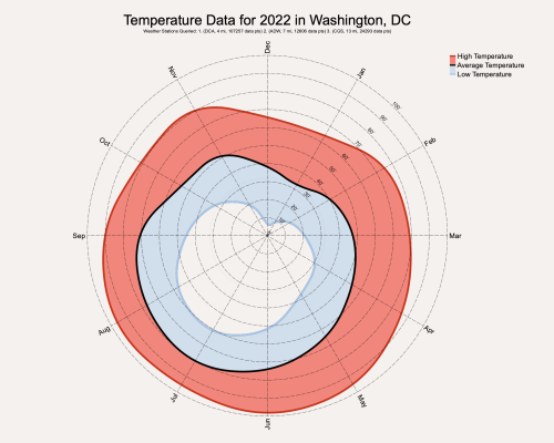 An excellent integration of climate data!
 -
 I'm unable to get this file to work. I've downloaded both versions and in each I get an "Index Error: List index out of range" message. I'm using the VW Designer 2019. The object loads, but as soon as I change anything i.e. mm to inches, it lists the error. Both the temperature and wind rose objects work, so I'm confident it isn't a network access issue.
 -
Vectorworks doesn't incorporate hyperlinks very well. So much of the BIM universe is web-based now, but I have yet to find a way to easily link that information into my VW documents. For example: In my plumbing fixtures schedule I would like to include a hyperlink to the product cut sheet. For my lighting schedule I would like to link to the fixture, lamp, etc. It should be feasible to include hyperlinks as a format in symbol data and then report that to worksheets, but I haven't been able to do it ... So, I looked to other tools and after a lot of experimentation settled on Airtable.com Airtable is a web based application that looks like a spreadsheet, but functions like a database. If your "table" contains less than 1200 items, then it is free for you and an unlimited number of collaborators. I find this amount to be more than ample for my residential projects. I have found the interface to be extremely fast and intuitive to use. Because it's web based (with controls built in for who has read-only or editing permissions), it allows for instant updates across the team. During construction I find this to be MUCH simpler than the constant re-issuing of sets. It also allows for crowd sourcing data from the entire team. For example, I provide my clients with a generic list of appliances and they fill in the ones they want. This shares the load of data management and ensures that my clients get exactly what they want. Here's an example of how it can be used: Lighting Schedule This link is to a basic template for light fixtures. We call out the symbols i.e. LX-101 on the lighting plan, but instead of including a worksheet / schedule in the drawing set, we provide a link to this table. One challenge of digital publishing is making sure that everyone is tracking changes. You can do this by disabling links to the database and re-issuing new ones with an updated issue date. That helps contractors etc. stay aware of updates, but since it's a database, you can rearrange sorting, display, etc. in any number of configurations. For our typical projects, we include product schedules for appliances, plumbing, fixtures, millwork, lighting and equipment. This tool has been a great resource for us and may be of use to you.
-
Twinmotion Plugin + Sync
Taproot replied to Tom Klaber's question in Wishlist - Feature and Content Requests
Twinmotion finally allows the level of rendering that I had hoped to get from Vectorworks. Aside from core VW stability my biggest request is to add a plugin so that VW can seamlessly update the model with Twinmotion. I'd love to make this my primary workflow (for presentations) but would prefer not to start over every time the design changes. Here's my first project using the two together.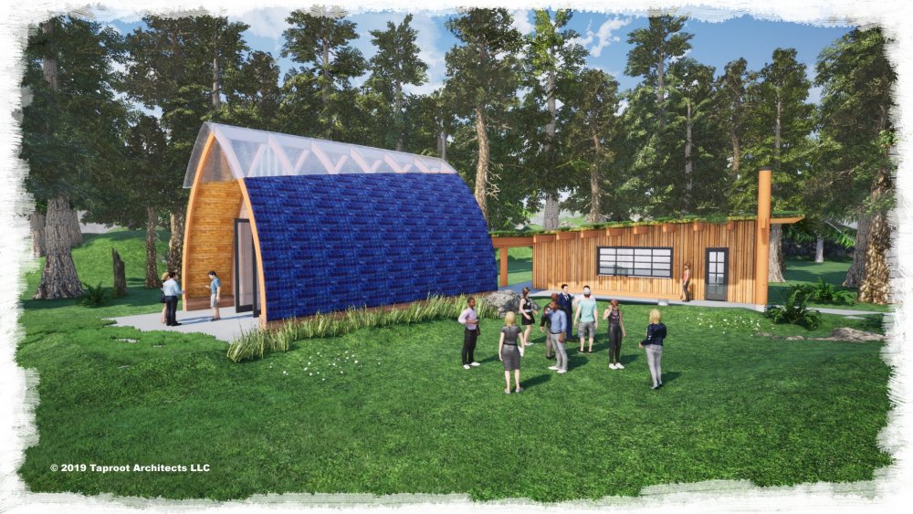
-
I just ran into this on the "add solids" command. It turns out that like you... it wouldn't work because the objects were on different layers. Perhaps just an error alert saying: " this function requires objects to be on the same layer" ? That would clue in the user to understand problem. Of course - Bruce's request to just make the software work more easily for the user is even better.