


Taproot
-
Posts
516 -
Joined
-
Last visited
Content Type
Profiles
Forums
Events
Articles
Marionette
Store
Everything posted by Taproot
-
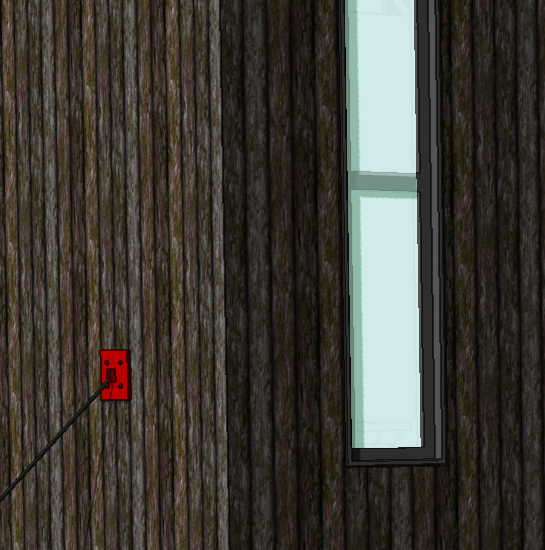
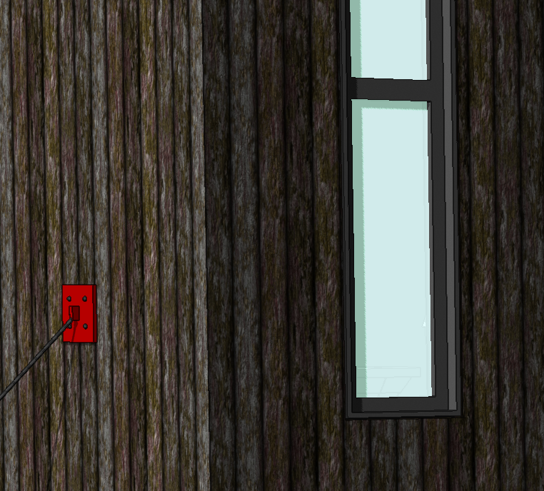
Windows with custom muntins don't render correctly in OpenGL. I had assumed it was a glitch that would get corrected in v.2018, but it persists. I have found that the muntins will disappear and reappear depending on the zoom level. I have checked that the muntins are indeed thicker than the glass and they are. Example of the same window at different zoom levels: The glass appears to overlap the muntins. In views where the sun is shining on the glass, the muntin will disappear almost entirely.
-
Will this feature allow the font list to finally display fonts in their own font style?
-

Shiiping container model wanted
Taproot replied to Cadplan Architecture's topic in General Discussion
Barkest may have already met your need, but sure ... here's a 2012 version of the file: Cargo_Containers_20_&_40_v2012.vwx -
Shiiping container model wanted
Taproot replied to Cadplan Architecture's topic in General Discussion
Here's a standard 20' and a 40' high cube. These are realistic in the sense that the surfaces are corrugated. If you are planning to modify the units, I've found subtracting / adding solids to be the easiest workflow. Cargo Containers 20 & 40 High Cube.vwx -
The hyperlink option is a nice touch. I'm very happy to see improvements to this part of the software.
-
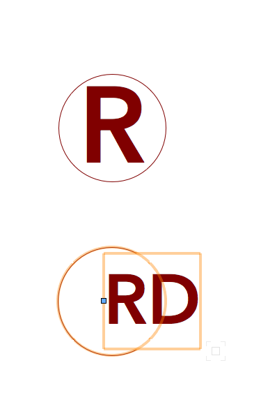
An old topic ... but still relevant. Even without custom symbols, this tool could be dramatically improved just by centering the label text. Currently, the "Config Label" is hard coded to a left hand alignment. Please change Ior offer the option) to center alignment. Since they are circles, the text looks best in the center. Every time we tweak one of these or change the scale of the text, etc, we have to manually re-center each one. Example image showing the '"R" recessed option by default (above) and the "RD" (recessed directional) applied via the Config. Label. Thanks
-
We use most of the features provided: • Issue notes and revision notes are per sheet. They actually work well once set up. We primarily use the revision notes to list modifications rather than clouding each drawing item (except when necessary). They list sequentially, so we can show prior issues or revisions along with dates for reference. • Our template is set up with a checkbox for each sheet as to whether it is in the drawing set. By default, the most common sheets are pre-selected (in the template), so we just deselect or add sheets as needed. In general, this works fine for a linear design process, but if we were to bounce back and forth between a schematic set and a construction set, then we would need to manually go through each sheet to reset the drawing index. I think you can get what you want out of the software, but it could be a whole lot easier!! My recommendation would be for VW to provide linking between the "publish" command and a drawing index worksheet. We're already setting up each "saved set" in the publish window. Why not have the option of "create drawing index" for the active "set". Ideally, users could have preformatted worksheet templates with the data for the titleblocks layed out the way they like them and the "create drawing index" would simply filter for the selected drawings. ... or some other way to limit redundancy.
-
Jim - that's good news!
-
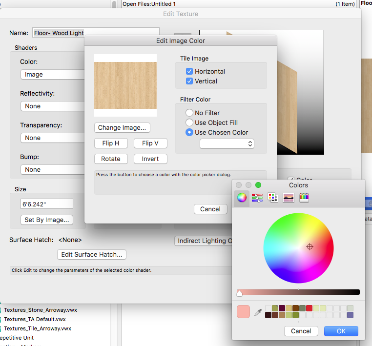
If you want to add a custom color filter to a renderworks texture - via the (mac) color picker, it won't work. The program stalls out. Fortunately, it doesn't crash. Toggling escape will get you out, but for now it appears that only pre-defined colors can be used as filters for textures. Here's an image demonstrating the work flow to verify that it's reproducible.
-
How to convince boss i am capable with VW
Taproot replied to CraftyCat's topic in General Discussion
If you are wanting to advance your skills, use an existing project as a guide and try and redraw it from scratch. That will ensure that you know how to use all of the relevant tools and better familiarize you with the process. -
I"m convinced this is a bug as well. A few years ago, I built a whole library of custom door leaves. They stopped scaling correctly (in the vertical dimension) around 2016. Now, they will only display correctly if the height of the door is the same as the original symbol. Doors still scale correctly in width.
-
It's been about 15 years since I started using Vectorworks and my eyes are starting to get tired of small point fonts. This is most noticeable on the Nav. Pallet where I'm trying to read through layers and classes and saved views (lots of them) in a compressed list format. Is there a way to control the font size of the pallet display? Nearly everything else in the program is graphical, but this one area really makes me squint. I don't really want to reduce my monitor resolution to enlarge everything ... but 6 point type is making me unhappy.
- 1 reply
-
- 3
-

-
It just needed a nap.
-
Thanks Gytis, I don't know how I missed that on my forum search ... but it's really useful to see others working through the same issues.
-
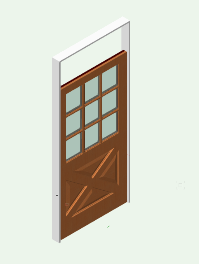
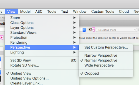
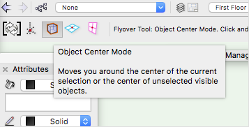
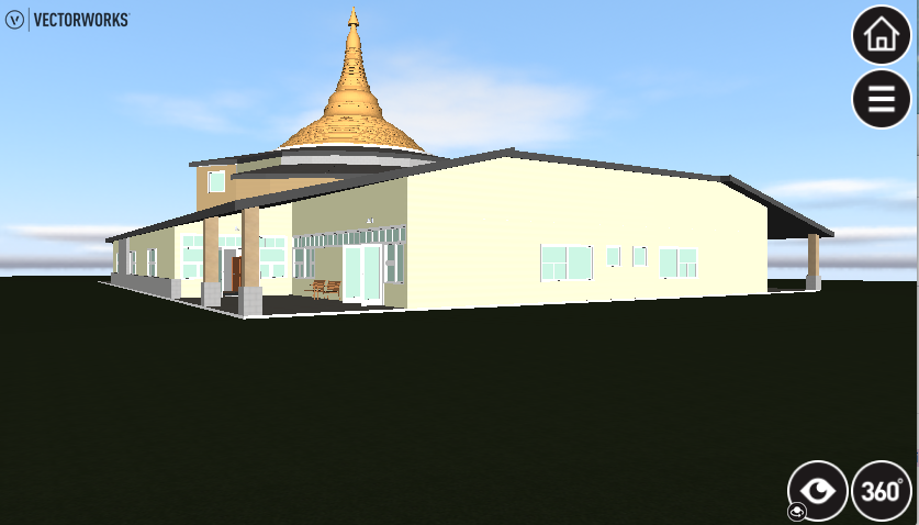
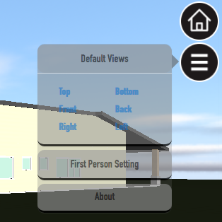
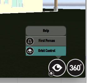
Thanks for the feedback (and confirmation). It's taken some time, but I'm slowly unraveling how to make the features work. Since there doesn't really appear to be any meaningful tutorials on this, I think I'll follow up with an "Idiot's Guide to Webview." I finally figured out how to make the desired perspective export. The bug is avoided by: Make sure that you are in "Object Center" mode. That reduces distortion when orbiting the model. Deselect "Cropped" from the View Menu > Perspective > Cropped. Note: That if you have a "saved view", it will usually reset you to "cropped." You will have to manually disable it prior to exporting. IDIOT'S GUIDE TO WEBVIEW Starting with a Desktop Browser. Opening screen: Clicking on the house (home) icon will return you to this view. It’s good if you get stuck or disoriented. The “Default Views” Button will give you standard orthagonal views of the model (not that useful). Better would be to have a series of user specified starting points so that one can quickly jump to different pre-selected perspective views. The “First Person Setting” allows you to set the viewer’s eye level when walking through the model. I like 5’-0” as a standard setting. “About” just tells you how complex the model is and the remaining time the model will be hosted on the company server. By hosting the files on your own server, this will become irrelevant. Clicking on the “Eyeball” you’ll have the option of “Orbit” or “First Person.” Orbit allows you to fly over, around and through the model. It’s the astral projection of the VR world … no boundaries. Once you have selected orbit, click and drag your mouse over the window. Left to right rotates the model horizontally, up and down rotates it vertically (or any angle in between). Use the zoom wheel on your mouse to zoom in and out. If you click on the Eyeball and then select “First Person,” you’ll be transported somewhere to begin your walkthrough. If you actually want to pick where you start the walkthrough from: Click on the eyeball, hold and drag … you’ll see an icon of a person. Where you drop the figure (release the mouse) is where your walkthrough will begin. It took me a while to figure this out. The figure must be placed on a surface for it to work. So, make sure that you have a floor slab in your model. Otherwise, the first person mode won't engage. Note, the beginning point is not the feet of the figure, but the cursor point at which you click. Once you have entered the first person mode, navigation shifts primarily to the keyboard. Use the cursor keys to move forward, back, left or right. You can also use “A,W,S,D” for this function if your keyboard lacks cursor keys. If you need to change your orientation, then click and drag with the mouse. It is slow, so you’ll likely need to click and drag multiple times. In this mode, you will not be able to walk through solid objects. That is why primary access doors are left open in 3D. You will be able to go up stairs, and down them again. The “360” feature does not work on the desktop. This is a motion based viewer designed for mobile devices. Navigating with a Mobile Browser. (My system is mac based, so I’ve tried this on an iPad and an iPhone) The mobile version looks promising, but it isn't ready for use. It can only handle simple models. My current project is too large to display. I have a lot more patience than I expect my clients to have and many of the features simply don’t work. For simple models, the navigation is more intuitive than the desktop. Orbiting works well with standard finger drags for rotation and pinching for zoom. The walkthrough mode appears to be broken … finger drags work for panning around, but the directional buttons don’t work. The 360 mode appears to be highly intuitive as tilting and turning the screen changes your view of the model in real time. However, looking at your feet to engage the walking feature doesn’t engage. “+,-, Walk and Pause” don’t activate. Therefore, while you can look around, you can't actually go anywhere. The view window often sizes itself so that the button controls are cropped off the screen and unavailable. On the iPhone, the bottom bar will pop up in Safari (bookmarks, sharing, etc) and won’t go away. There are enough interface issues where I’ve finally given up trying to make the software run on a mobile device. If the VW staff has comments (or solutions) to any of the above - please chime in. p.s. the "Vectorworks" branding on the Webview window is tacky. Published output to my website or a client's website isn't about marketing the software. It should be about creating a polished and professional experience.
-
I've been using a lot of trial and error to figure out Webview. It's time for some help! How do you set the initial starting view for the export? I've tried setting it via a saved view, camera, etc. The webview start location defaults to the same spot ... off kilter and near the floor. There must be a setting or logic that I'm missing - maybe both? I have about 375,000 faces in the model. In the browser, it does OK, but my ios device reloads the link after a short time citing an error. Is there a functional limit to the size of a file that a mobile device can handle? Navigating takes practice. In the first person walkthrough mode - on the browser, it's really difficult to reorient yourself. The building we are modeling is round with curved hallways, so adjusting trajectory is common. Changing orientation seems really sluggish with the mouse in between moving forward, back, etc. What is the best way to change your orientation? Navigating on ios in 360 mode doesn't appear to work. Looking down at my feet, no amount of tapping on the walk icon, pause, or + or - results in a result other than ... lots of tapping. I've tried this on both an iphone and ipad to no avail. Orientation on the touchscreen is much easier, so if the walking feature were to work, I can see how this would likely be the preferred platform for navigation. Walking through on an iphone in first person mode, the Safari bottom bar pops up and won't hide. Since it overlaps the user controls, it makes navigating pretty near impossible. Is there a way to disable it while viewing a webview file? Is there a way to set up multiple saved views for the webview export? It defaults to front, left, bottom, etc. I'd love to be able to reset these to: Lobby Perspective, Stair Perspective, etc... That would save user frustration in trying to get from point A to B to C, etc. I suspect the answer is to export copies of the same model from different starting points ... assuming that you can of course consciously set the starting point. Thanks.
-
Until then... a workaround that eliminates the guessing: Measure the object and the space you want to fit it to - then let the scale command do the math. For example if the object measure 5.5 and the space measures 1.25, then input: 1.25 (space size) / 5.5 (object size) into the scale command and it will be resized to fit.
-
I was referring to the use of Class Overrides in viewports to adjust visibility. For example if the cut plane height were the problem, turn off visibility of classed objects above that plane or override the class to change them to dashed, etc. I'm just guessing ... If Alabama posted an example of a plan with comments on the desired result ... then we could give more constructive advice.
-
It looks a little bit like lines with an end marker turned on (i.e. a circle instead of an arrow). Sometimes, I find that if I have a line setting with a marker set as the default attribute and then I create a viewport ... that odd things like this can happen. If this is indeed a viewport, try turning off end markers and then recreate the viewport and see if that works.
-
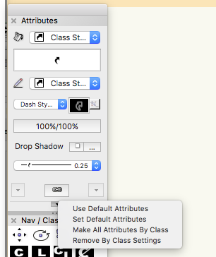
Hello Alabama, I've talked to folks who have migrated to VW from Revit, and once they get the hang of it, invariably, they like it better. The versatility of the 2D tools and the ability to fine tune the drawing precisely in 2d and 3d is the main plus. VW sacrifices order and organizational clarity in favor of user control and flexibility. So - getting started it can be confusing, because there is often more than one way to do things. Later, it's a blessing because you can almost always find a way to achieve the result that you want. Regarding the plan view - your viewport settings in the OIP should be set to View: "Top/Plan" and Background Render "Wireframe." Controlling visibility of objects is usually fine tuned through the use of classes. Jim answered this pretty well. If you have an object that you want dashed in plan view (say a beam above or a roof). You would need to set the objects' attributes to "by class." It's the funny box with an arrow pointing up in the Attribute Pallet. You can do this quickly by selecting "make all attributes by class" from the pop up menu at the bottom. Then in the viewport, you can override the class settings ~ i.e. changing the fill to none, the line to dash, or you can just turn off display of that class. There are ways to adjust the "slice height" of a plan view, but it's complicated and you would be better off learning the conventional way first before improvising too much. The standard for section cuts is to set the Background Render to "Hidden Line." Details: Personally, I rarely link my details to section views. The reason being, that I routinely copy details from older projects and work with a large library of standards that are easy to modify in 2d. Having all of my details on one 2d layer tends to be more efficient - as I can easily move notes, hatches, and objects between details without having to enter and exit viewport annotations. The way you described - enlarged viewports with annotations is common enough, so experiment some more and see what you like. As your base information and templates grow, you'll see remarkable productivity gains ... and much more comprehensive drawing materials. Modifications in design telegraph through the whole set and worksheets do a remarkably good job of reporting that information in clear and concise terms. Here's a good starting place for worksheet help: http://app-help.vectorworks.net/2016/eng/VW2016_Guide/Worksheets/Worksheets.htm
-
You should be able to accomplish what you are trying to do. One possibility is that you are adding annotations in a class that is turned off (i.e. not visible in that section viewport). Verify that your annotation class is turned on before adding items to the viewport.
-
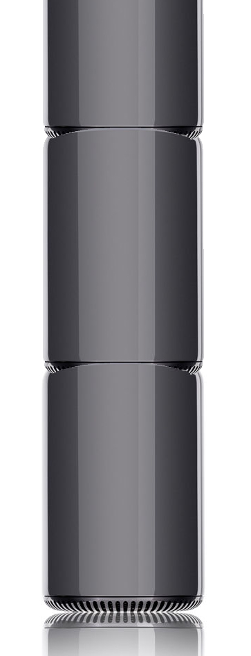
How about the "Tower of Power"??
-
Here's an interesting article posted today about Apple's commitment to upgrading the Mac Pro. It's not coming this year, but it is coming .... https://techcrunch.com/2017/04/04/apple-pushes-the-reset-button-on-the-mac-pro/
-
Drawing Label wishes
Taproot replied to michaelk's question in Wishlist - Feature and Content Requests
That sounds like a great solution! -
I was discussing site location maps with a colleague. Notably, how expedient and ugly it is to copy and paste a "google map" onto a beautifully rendered cover sheet. The discussion motivated me to look for an alternative - a way of presenting black and white line drawing maps without actually needing to trace them manually. After some research, I discovered "Snazzy Maps." It gives the user control over google map attribute display, I've set up a style which does what I want (I just add labels). You can access it, many other styles, or create your own. Link here: https://snazzymaps.com/style/99435/architectural-location-maps