


domer1322
-
Posts
584 -
Joined
-
Last visited
Content Type
Profiles
Forums
Events
Articles
Marionette
Store
Posts posted by domer1322
-
-
Jim:
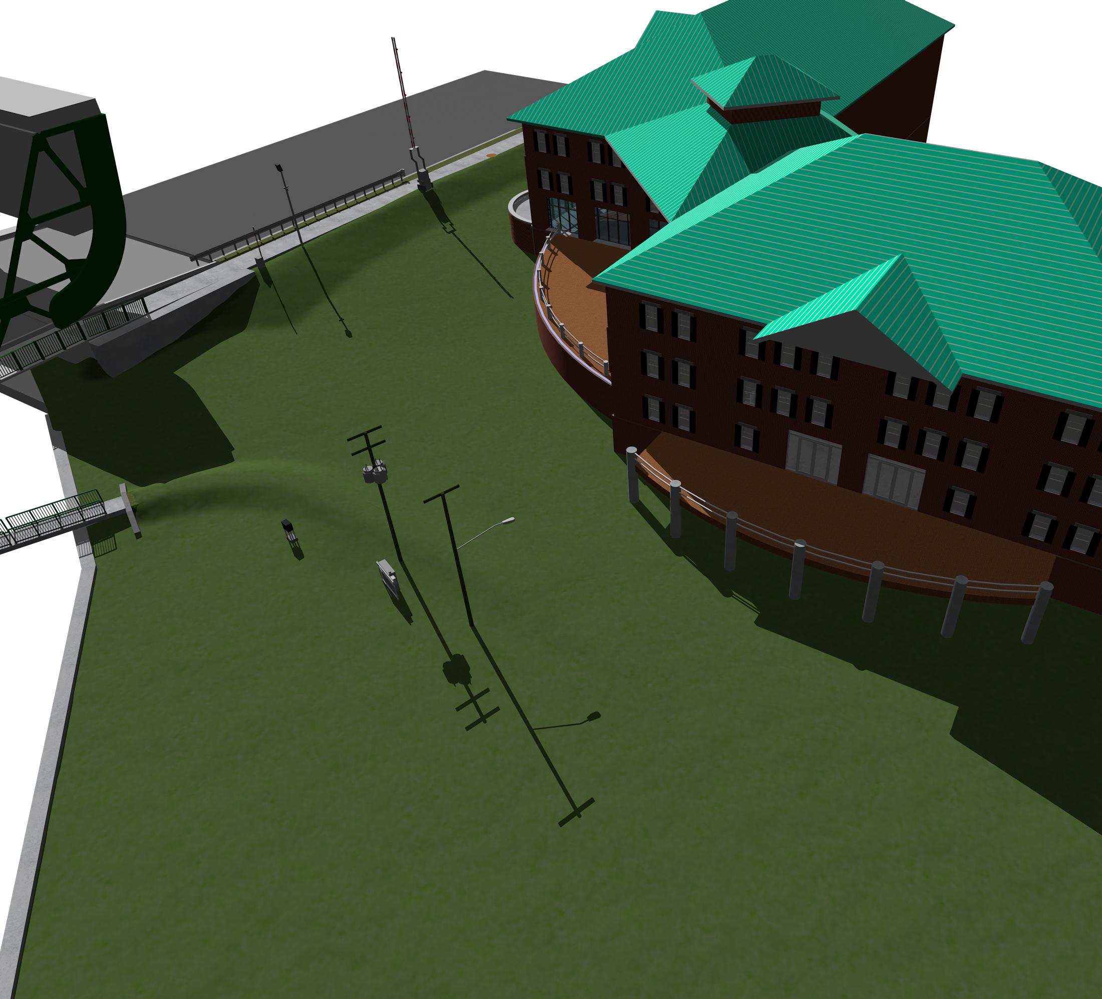
I would be happy to send you the file, but there are some complications. The main file is a site with DTM and is over 120 Meg. It uses an external reference file for the building, and that file is over 200 Meg. Both use VW2015. I don't know your email address, but even if I did, how could I get these large files to you ?
I attached a still image to give you some idea of what I have modeled.
-
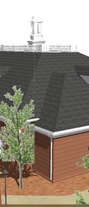
I attached a "grab" image of an animation where there is a very fine vertical line exactly in the middle of the movie window (look at the upper roof). Interestingly, the fine line also chops off the edge of a tree. As the movie continues, subsequent frames restore the edge of the tree, but the line remains, always in the center of the image. The animation is an OpenGL rotate 360 deg, 30 secs long, with quality set to 'high'. The line occurs exactly in the middle of the rotation axis. I do not see this line nor the tree cut off using RW. However, RW seems to always yield an offensive moire pattern in the bricks. Also, the tree in question is a default image prop tree from VW, and the same thing happens to other copies of the same tree (and other trees). I have another tree from a different source "VBPlant" and it does not chop off.
Can anyone explain this ? ... or better yet, tell me how to avoid it ?

-
Mike and Markdd:
Thank you so much ... that solved it. I guess that "cast shadows" check box on the texture was another obvious feature that wasn't so obvious to me ....
-
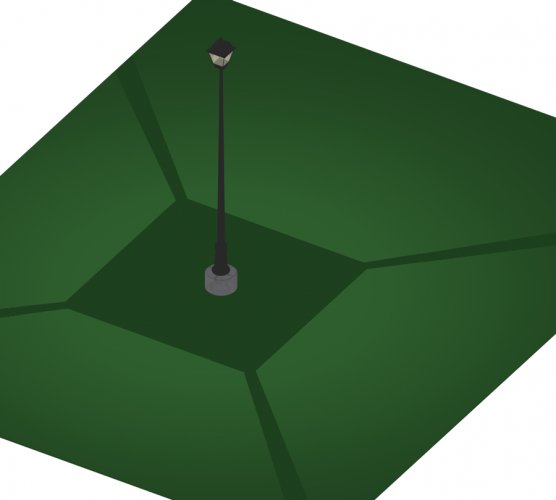
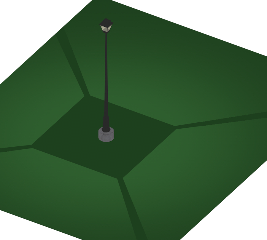
If you look at the attached image, you'll see a problem that has perplexed me for years. How do you put a light object inside a light fixture, then realistically show light emitting from the fixture that doesn't show the structure of the fixture ? In the image, I have a street light casting shadows from the light structure, but in real life, it never casts shadows like that.
I know I can make the light fixture with a transparent texture and the light goes through it, but then I can't see the fixture. I also know I can set the light to not cast shadows, but then it doesn't act like a real light would do (it wouldn't cast shadows on anything).
Is this possible or should I give up ?
-
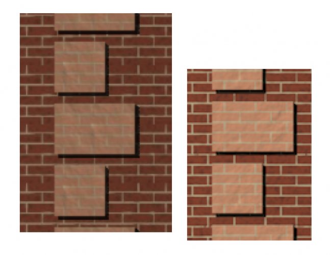
If you look at the attached image, it shows the same wall corner with quoins, rendered in OpenGL (left) and Final RW (right). Notice that both textures make a shift in the brick joints. Thus, I can render it with the joints lined up in one render mode, but if I switch modes, then the joints no longer line up. This is NOT a matter of using "world origin" since I tried it both with and without that checkbox marked. Also, notice in the left image the horizontal joint seems to be skipped for every 6th course. I am primarily interested in getting the horrid joints lined up, but notice the vertical joints also shift.
Can anyone tell me how to fix this ? Is it fixable ?
-
thanks for replies ...sounds like there is no solution. I usually think these things are operator error. Benson: I have also had the "duplicate DTM" error that perplexed me, but this time, that is not the case. Glad to know I'm not the only one .... guess that only happens to each of us just once.
Also (J Wallace): I also find texture beds very tricky .... but is there any other way to use a Google Earth image for the site model with contours and showing 3D elevation changes ?
Also: does anyone else notice frequent crashing when trying to render large sites using 3D extruded contours setting ? It happens to me so much in both Open GL and RW that I no longer even try to use 3D extr contours and always use 3D triangles.
-
Can someone help me with this .... when I make a texture bed on a DTM site model, they frequently show "interference" in 3D views, much like you get when two objects occupy the same plane. It also appears as if portions of the underlying site DTM are "poking through" the texture bed. I can fix the problem by going to the OIP and adjusting the elevation of the texture bed by a few inches above the DTM, but then the 3D image looks like it has a "floating carpet" above the DTM, instead of mapping perfectly to the surface. How can I get the texture bed to map precisely to the DTM ?
-
Zoomer ... thanks for the reply. However, it seems there is no easy answer here (as I suspected). Can anyone else recommend the best way to import 3D geometry (and textures) into VW 2015 ?
-
I ask for some simple advice from you seasoned pros out there ...... i have a very large file of a museum building that I've been working on with the intent of making it suitable for photo-realistic 3D renderings of interior spaces. The building owners will soon hire a museum exhibit designer, and it seems likely that the designer will not be using Vectorworks. I intend to import their 3D design exhibits into my 3D museum building, so that I can show how well the exhibits work with the building.
Here is my simple question: if I could dictate what software the exhibit designer uses (other than VW) what software file format will be the easiest to import into my 3D model ? Important point: I'm using VW 2015, so a Revit import is not possible.
As you might expect, I want to import their work "as is" without having to re-generate solids or apply new textures or have to break the 3D files into a million polygons.
What do you think will work the best ?
-
is there an easy way to simultaneously change every cabinet door pull in a kitchen cabinet group ? That is, I might have a dozen different kitchen cabinet plug in objects, and if I decide to change the style of door pull, I have to go back to each cabinet and change each one in the 'settings' OIP. There must be a simple way to change all the door pulls or handles easily. Please someone tell me ....
-
it worked ... thanks. The key thing is that the OIP field for "section Line Instances" is only found when the section viewport is activated. I was always looking for something when the plan viewport was activated. When I'm looking at the plan, there is no option for "section line instances". Thanks again ...... I knew it would be easy for someone who knew what they were doing.
-
this should be an easy question for someone who knows what they're doing .....
I have a 3D model, and I used the menu command "View > Create Section viewport..." to make a section viewport on another sheet layer. The section line marker shows nicely on the design layer where the 3D model is, but on the section viewport sheet I can not get it to show up. I checked the viewport settings to ensure all the classes and layers are turned on, as well as the "project screen objects" and "display planar objects" are both checked. This ought to be simple ... but I'm puzzled. Help please.
(incidentally, I can use the toolbar to make a "section - elevation marker" that shows nicely in both design and sheet layers, but I figure there must be a better explanation.)
-
Benson ... thanks for the ideas.
Alan: this may disappoint you: I'm retired and I'm doing this as a volunteer. Thus, I didn't upgrade my VW and I'm using VW 2015. Hence, I don't have Marionette and I don't know if I ever will. Sorry I led you down a path that isn't useful (for me, anyway).
All: thanks for the help.... I've always had trouble manipulating a DTM and showing grades in 3D and this is a good learning experience. My current technique is to get the DTM as close as possible, but it always has odd rendering of the grass and I also have trouble with texture beds. Thus, I get the DTM as close as possible, then use a draped surface (with cut outs for the hardscapes or other objects) and produce a final rendering. The draped surface always shows the grass or mulch much better than I can get with a DTM and texture beds.
-
thanks for the help. I found Alan's "wall technique" doesn't work for me because I am modeling an entire park and it is too laborious ... plus i can't seem to get the pavers to be the correct size (4x8) by manipulating the texture scale.
I guess I'll use Benson's "multiple symbol" approach. To my surprise, having thousands of individual brick symbols in the file does not seem to slow down the render times as much as I thought it would. It might be the best method, but it still takes a lot of time, since it has to be done separately for each curve.
One additional question: after I duplicate the brick symbol along the path, I send the bricks to the surface of my DTM. However, each individual brick remains co-planar with the original ground (flat) plane. Is there a way that the bricks could be slightly tilted so that each brick is sloped to match the grade of the DTM at the location where the brick is? Most of the time this is not necessary, because the difference in the "sloped" plane is negligible, so my question is more theoretical than practical.
-
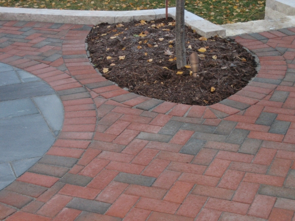
I ask for help: I've struggled for a long time trying to make a realistic 3D model and rendering of a landscape path (or area) that has brick pavers on the edges, like that shown in the attached photo. Can anyone give me a suggestion on how to do it well ?
My main problem is that I can't figure out how to make the edge pavers be perpendicular to the edges for a curvy pathway. I know I can use the hardscape tool, but that doesn't allow for a realistic rendering of the pavers using RW in 3D. Using the "border-joint pattern" settings will yield a hatch that has perpendicular lines, but it is only a hatch and not intended to be "photo realistic". I appreciate any help ... or .... just let me know that you don't think it is possible so I don't keep trying different things that ultimately don't work.
-
Bingo ! Christiaan - you got it right. First I changed the Navigational Graphics from being checked to being unchecked. It had no affect (maybe made it worse). Then I took the VW default wall style for brick veneer with 6" stud cavity insulation and removed all the component hatches (except brick veneer) as Christiaan suggested. Now it scrolls and zooms fast. Case solved ... thanks a lot Christiaan.
However, I am disappointed that using the standard VW-provided wall style caused this to begin with. For this job, removing the hatches doesn't matter ... but I envision sometimes where that would be a problem.
-
I drew a site in 3D, and recently added a "shell" building as shown in the attachment. There are no interior walls, only the exterior walls and a roof. After adding the walls, I suddenly noticed the screen redraw of the walls in top/plan view are unusually long ... about 3 seconds per wall, or about 30 seconds for the whole thing every time I scroll or zoom in/out. I'm not used to any redraw delay for top/plan view, so I figure something must be wrong. Any suggestions as to what is wrong or could cause it ? I did not use "stories" for the walls, I just duplicated and moved them up for each floor. There are no interior walls, slabs, or any other symbols. I've had much larger file size drawings without this issue (size = 95 Meg) so I'm puzzled. When using RW or OpenGL everything renders as fast as normal. Any thoughts ?
-
OK ... eventually I got it to work completely correctly by redrawing the 2D component ... but it didn't seem to work in a predictable fashion ... I sort of stumbled upon the final correct version. Anyway ... thanks a lot for your help.
-
thanks for the help .... I tried the copy and paste idea, and it didn't work, until I added 2D loci. However, even though I got it to work satisfactorily, it still has an odd quirk. Look at the attached image file to see that the symbol fits in the 2D top/plan wall nicely, but when I select the symbol, the selection box indicates the larger size that was the original problem. I am perplexed, but I guess I should accept partial success and move on .....
-
this ought to be easy ..... I attached a 2015 VW file with a hybrid door symbol that I built myself. I'm very frustrated that the door symbol, when inserted into a wall, has a large blank space (about 2 ft) to the right side. My obvious thought was there must be a "stray" locus or 2D object causing the large gap in the wall in 2 D top plan. However ... I'm stumped. Anyone care to help ?
-
need simple help ... in the attached image, I applied a texture bed to a sloped grade and it is rendered in RW. How can I get rid of the white lines that mark the edges of the texture bed ?

-
This is a good topic .... so I'm keeping it current ....
Jim: by your response about pdf file cropping you seem to imply that cropping a pdf image will make the whole file less "heavy" ,,, that is, it will draw, scroll and zoom faster. Is that true ?
That also implies I should also import images as bitmaps or jpeg files (not pdf) , unless I'm trying to snap to points as can be done with a pdf. True ?
-
great ... but ever since VW started this new forum format, I can't figure out how to look up my old threads .... so I don't know how to get to that old thread ... help ???
-
I need help ... I'm trying to render a stained glass window. When I make the image prop and related texture, I adjusted the image mask for levels of gray/black transparency, and the light comes through the window according to levels of black in the image, but it doesn't show the colors in window. That is, I expect to see the light reflecting off the floor to be the color of the stained glass. As a bonus, it would be nice to directly look at the window and see the colors "glowing". What I see now is the various levels of grayscale render as transparent (clear) glass. How do I make this work the way it looks in real life?

Resource Browser image size
in Wishlist - Feature and Content Requests
Posted
Is there any way to change the image of a texture in the resource browser ? I am frustrated by several default files for textures that show stone textures for the preview image in the resource browser and there is no way to tell what the actual texture looks like by seeing the tiny image in the resource browser. I attached an example .... notice on the left is the image of the actual texture, but there is no way to know that by looking at the image in the browser.