


Ned Daugherty
-
Posts
16 -
Joined
-
Last visited
Content Type
Profiles
Forums
Events
Articles
Marionette
Store
Posts posted by Ned Daugherty
-
-
All, I've imported a plan view image of an existing landscape and have drawn new objects over it. When I view the drawing from any angle other than Top Plan or Top View, the 3D objects appear slightly obscured, almost like the background image is partially transparently covering them. And when I tilt the drawing at a very low angle (approaching a horizontal ground plane or "Front" view), I can see that the upper portion of the 3D objects I created are not obscured. It sort of looks like the background image is in a plane that is above the bottom, although I've sent it to 'Back.' I've tried both PNG and JPEG. Maybe some setting is incorrect? I've done this before and not had problems... Thoughts appreciated.
-
Hi All,
What's the best way to minimize file size when using photorealistic 3D tree graphics for both 2D & 3D renderings? If I place 3D trees directly in the drawing, the file size is huge, even if using them as symbols. But, if I use a photo prop, in plan view it only shows a "+" mark, and not the plan view of the tree.
Thanks!
-
Jeff, many thanks! I will do as you suggest. Much appreciated. Will revert if further challenges.
-
 1
1
-
-
Appreciate the assistance. The attached file is georeferenced. For some reason, when I create a site model, extra contours appear. The intervals on the correct Conceptual Master Plan (3D polygons) are 0.5 meters apart in the Z. Notice that on the site model (above the CMP), the relative x,y spacing/positions are different and there are extra contours added (particularly on the upper/higher contours).
Also, I would like to overlay the aerial (actually a live georeferenced link to a server active on the Conceptiual Master Plan drawing) on the site model topo - or is that not possible because it's a live link? maybe I have to just capture a bitmap, then overlay it? If the latter, what the best procdeure for doing so?
Thanks VERY MUCH!
Using VW 2021 on my laptop with NVIDIA Geforce and Intel Core 17
-
When I create a geoImage, and trun off the background georef image, the one I creaeted is super dark. I can barely see it or use it. Am I doing something wrong, or is there a way to lighten the new geoImage that I created (not reduce opacity, but actually lighten / brighten the geoimage)? Please see attached files; one with the original, total georef image (esri server) and one with only the geoImaged rectangle. Or maybe another server service? really appreciate any help, thanks.

-
Thanks Pat!
-
I've recently purchased VW 2021-Service Select from a previous educational version. Is there a way to copy/past or import previous watermarked drawings so I can continue working on these drawings without the watermark?
I noticed a question in the install that asked if I wanted to use / keep previous settings, to which I asnwered 'yes.' Is this maybe the issue? If so, should I uninstall and reinstall VW 2021 and say 'no' to this question (so it will load with no previous settings)?
Thanks in advance and Happy New Year!
-
Thanks for the reply.
The DXF was generated in QGIS and is attached herewith.
Thx
-
After import of a dxf file (contours) I cannot see the file in the new layer that is created (even tho the report indicates that import was successful). Seems like the new layer may be faulty (or more likely, operator is!-)
Appreciate any thoughts, many thanks.
-
I'm new to the georef features of VW, so excuse the level (and confusion) of my questions. And, I have reviewed many tutorials and YouTube videos, but could not find any that state, very clearly, in a step-by-step fashion, how I can achieve my goals.
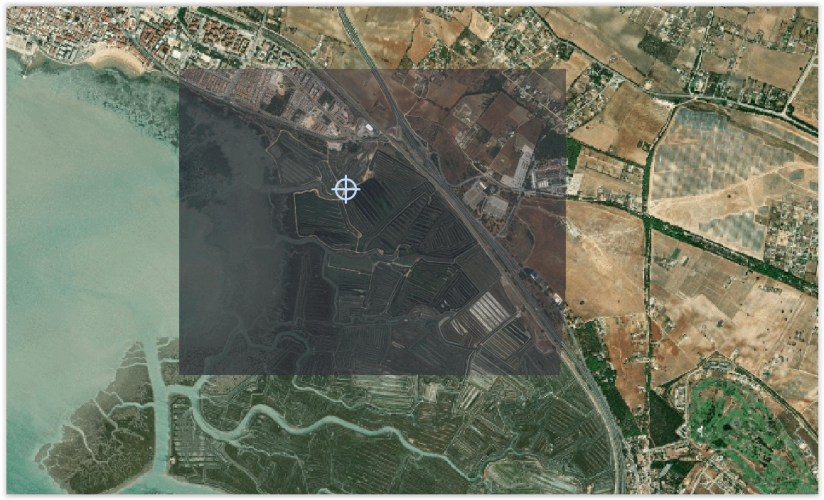
I have georef'd my document (drawing file) to a location in Baja, Mexico (see Image 1 - Doc Georef window & site Prop attempt) :
Lat: 26.85345237 Lon:-113.14065865 using current EPSG: 4485 CRS: Mexico ITRF 92 / UTM Zone 12N Units: MetersI am trying to:
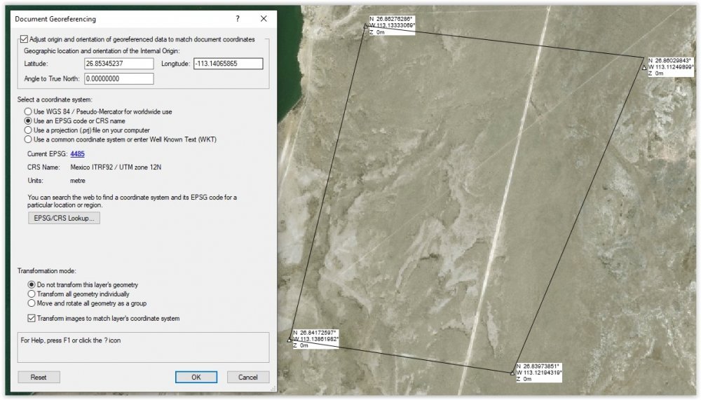
1) Draw accurate site property line, using coords from "Image 2 - source corner point loctions" (I did convert coords from deg/min/sec shownin the photo to decimal degrees of my drawing).
Question: I have used the GIS Stake Tool and moved the stake manually to nearly the exact location, then drew connecting property lines (not with Propoerty Line Tool)(see Image 1 - Doc Georef window & site Prop attempt).
Is there is a way to just type in the coords and have them move the stake to the exact location? If so, step-by-step how?-)
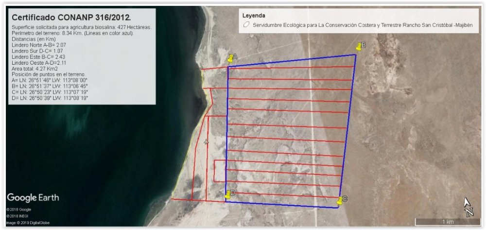
2) I would like to drop several 3D Loci to several specific coordinates on the same georef'd drawing as above, using coords from a csv table that I have created.
The coords in the csv are in decimal degree format, from drone image metadata that I have converted from Deg/Min/sec using ExifTool.
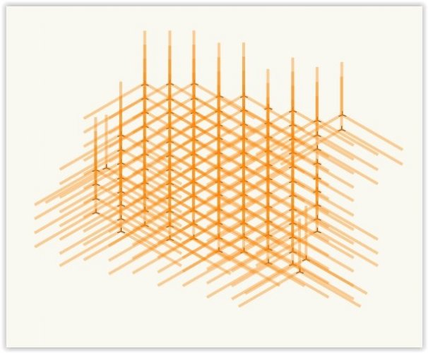
My attempt at doing this just clusters them in one location (see Image 3 - Import Coords Cluster and Image 4 - Closeup of Image Coords Cluster)
Questions:
a) How can I import these coords so they are dropped as 3D Loci at the respective, correct x,y,z coord locations?
b) Is the problem somehow with the scale of the imported coords?
c) Is the problem that the coords somehow need to be georef'd to match the document georef system that I have set up and am working with?
d) I also want to import the actual .jpg images to their respective coord positions on this drawing. When I do a tet of this, for just one image, it comes in very large
and not centered in the correct location.
How would I import the images 'en masse' and have them land in their correct, respective positions, at the correcct size?Would I need to define the scale, somehow?
Would I need to somehow set or adjust the coord system in the metadata so they come in at the correct location?Apologies for the tome;-(
Many, many thanks for thoughts/suggestions!

-
I am renovating an existing wood deck and want to inventory my existing materials. I thought a report would be good for this, but am having trouble understanding how to create one.
Must all elements in the report be symbols (i.e., must every component (board, post, etc.) be a separate symbol)? Would a spreadsheet (worksheet) be better for this purpose?
I have research this to the point that I am now thoroughly confused. Is there a concise, simple, step-by-step resource I can use to follow instructions? I have referenced both Jonathan's and Tamsin's books (which I love and have used successfully for many issues) but can't find a simple process to achieve what I need...
Appreciate any suggestions. Love the forum and community!
Thx in advance, Ned
PC, Windows 7 Ultimate, VW2016 Designer
-
When I import .png, .jpg., .pdf, etc. image files they still have background, even though I check the radio button to bring in as a .png (as opposed to a .jpg). How can I import with a transparent background? Thanks for any suggestions.
-
Thank you gents, both approaches worked very well, although the subdivision will take a little playing around with to become fluent.
I certainly appreciate the entire VW community and all of you that are passionate and dedicated to the product, users and 'VW philosophy.'
Cheers!
-
I'm relatively new 3D aspects of VW. I'm trying to create a curved surface, using straight lines. The finished shape will be a hyperbolic paraboloid (curved, but made up of straight lines). I've drawn the straight lines and have the shape that I want, but I can't see how to make this series of intersecting lines in to a uniform, 'solid' (curving) surface. I suspect there is a relatively simple way to do this, but I'm not familiar enough with all the commands to know how to do so. A detailed, step by step would be greatly appreciated. Thanks in advance.
Using a PC with Windows 7 Ultimate, and VW 2016
-
I'm fairly new to vw. I've run in to a couple of problems that I have tried to solve, but now need help from the more experienced community. Both issues have to do with exporting a pdf.
a) When exporting a vw drawing file that has an imported pdf that has been cropped, the resultant image shows up in the new jpg file rotated upside down. For example, if I import a pdf of an aerial photograph in to vw, then crop it (on a drawing that has a title block) and try to export it as a jpg, the new jpg has the title block in correct orientation, but the original cropped pdf image is rotated 180 degrees. Very odd.
b) When I export a vw drawing file to a pdf, I get a message saying I don't have appropriate security, and it won't let me do anything with the file.
Any help is most appreciated, Thanks
OS: Windows 7 Ultimate, 64 bit, 16G ram
VW 2016 Educational Version
Nedly


Background bitmap image obscures 3D objects
in General Discussion
Posted
Thanks Pat, I tried that and it still shows the 3D objects as partially obscured by the background image when I look at site from an oblique view (background image is now on a separate layer, beneath the design layer). Please see attached.
I would send the file itself (and will try to if necessary), but it is huge - I am struggleing to create & place image props, which are new to me (I have PNGs I made but they are not coming in with transparent backgrounds and the 'alpha channel' button in Create Image is gray - although my understanding is I shouldn't need it if it's a PNG). I've watched several videos but none address my issue. Many thanks.