
zeno
-
Posts
972 -
Joined
-
Last visited
Content Type
Profiles
Forums
Events
Articles
Marionette
Store
Everything posted by zeno
-

Find a Plug-in Object so I can Delete a Class?
zeno replied to Bruce Kieffer's topic in Architecture
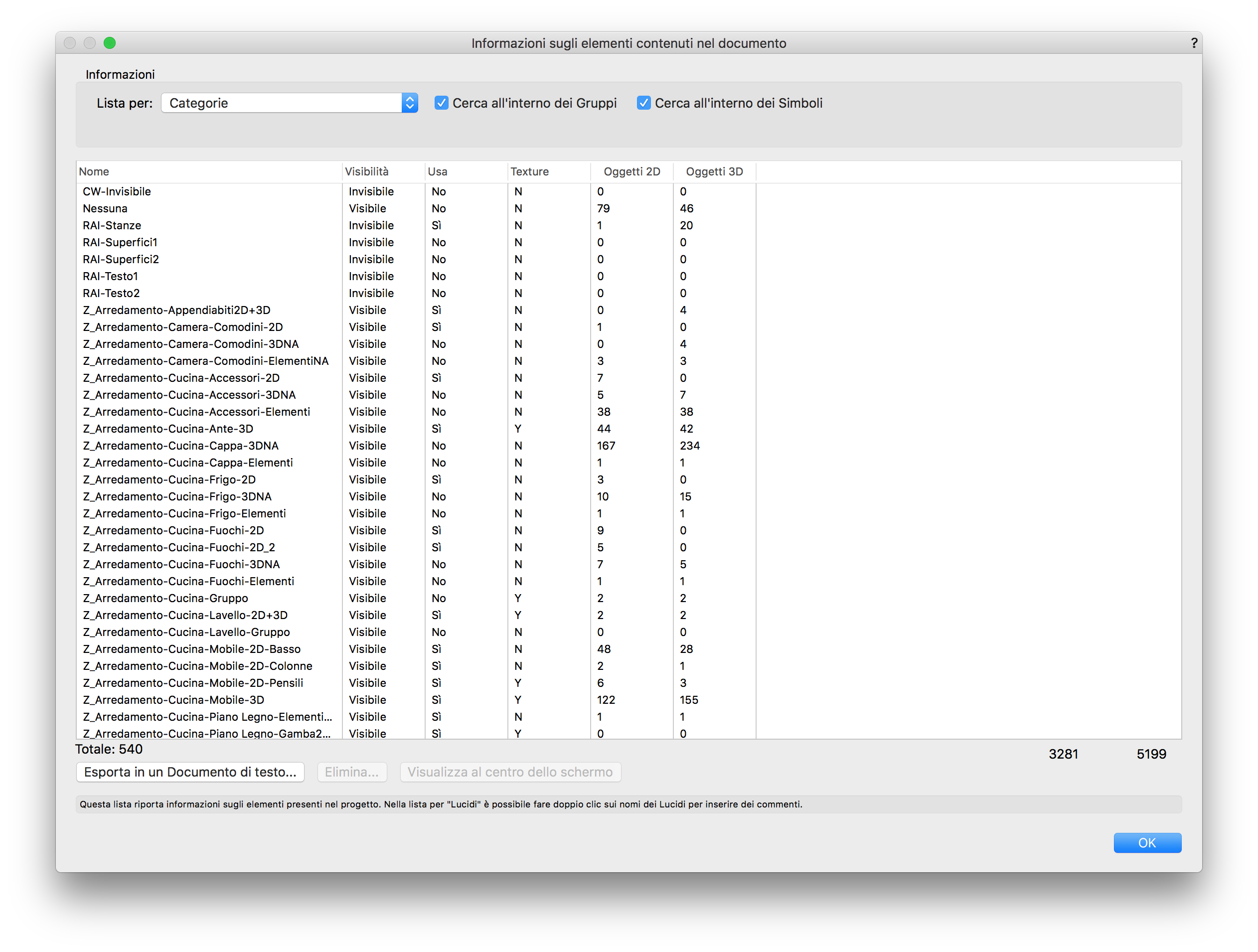
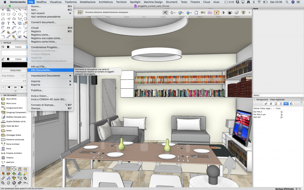
In Italian version is in the file menu>document info or info document (I don't know exactly, I attached some screenshot)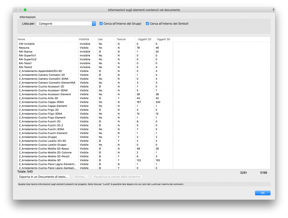
-
Hello I'm not totally sure I'm got it, but: Do you need something like multiple pages in a sheet layer or what?
-
Find a Plug-in Object so I can Delete a Class?
zeno replied to Bruce Kieffer's topic in Architecture
Try to see on File>Document info if you can understand how many 2D-3D objects are in the class. It could help you to better understand. -
Find a Plug-in Object so I can Delete a Class?
zeno replied to Bruce Kieffer's topic in Architecture
Exactly. It is the right way I mean. -
Find a Plug-in Object so I can Delete a Class?
zeno replied to Bruce Kieffer's topic in Architecture
Do you have something on resource browser? Like a door style or similar? -
Find a Plug-in Object so I can Delete a Class?
zeno replied to Bruce Kieffer's topic in Architecture
Try to enable and disable manually the class. All design layer on.. it is not very professional but for me, it works every time I'm in the same situation... But yes, something like right click on the class name>select all object in this class should be very useful. -
Thanks markdd, i hope that on next versions will we see something like "see clip cube" on a viewport in a sheet layer and stop. But for now i can try.. maybe will i post an example with a rendered viewport here..
-
So if i correct understand the process is 1) turn on the clip cube in a design layer 2) set the view 3) create a viewport on design layer 4) re-create a viewport to see it correctly on the sheet layer and render it if you need? It should be called a matryoshka viewport!
-
Hello, does this trick work even with a render style? Thanks
-
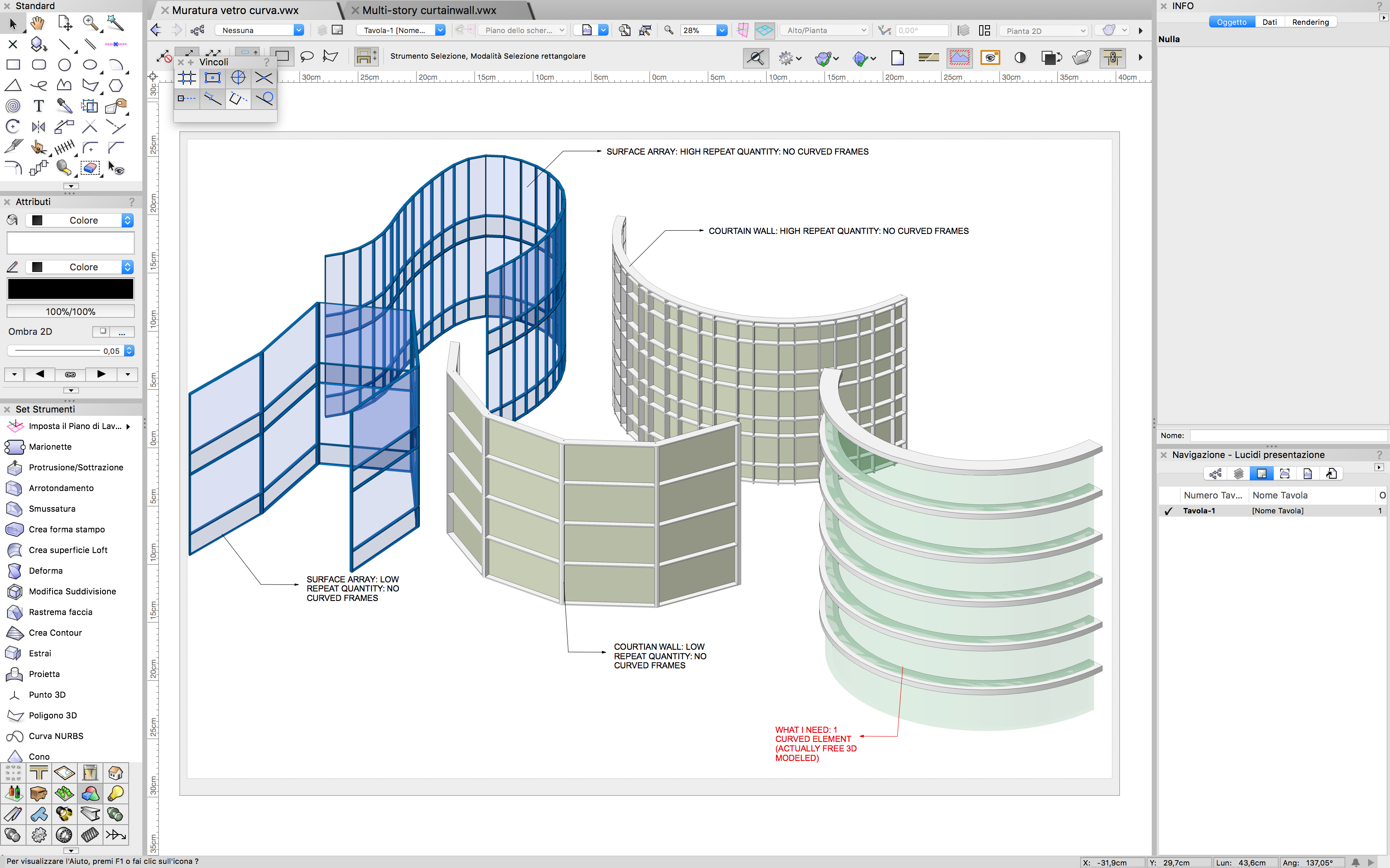
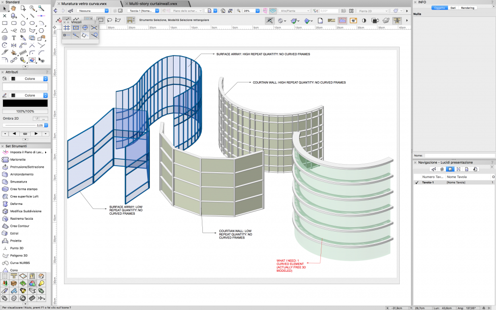
Hello Wes I'm honored to receive an answer from you, I follow your webinars for almost a decade. I understand the priority of construction process. But I think that in a design process the best way is creating what you need to create. If we were to draw everything that is already there, we would not be architects, do you think? And if I draw a curved wall I should have the chance to generate curved glass. I'm not a software engineer, but I do not think is something difficult to define. Of course, I can create an auto hybrid element and resolve my problem in my way. But these things are exactly the things that may you think "why others BIM softwares can do this?". We are talking about a curved glass on a curved wall, not generating a bim model by scanning a sheet of paper.

-
Thank you Benson. I was hoping for a better solution, like an option in OIP "create curved elements" or similar. Ever more convinced that the wall object should be reviewed in Vectorworks. For the moment, I will follow your suggest. Z
-
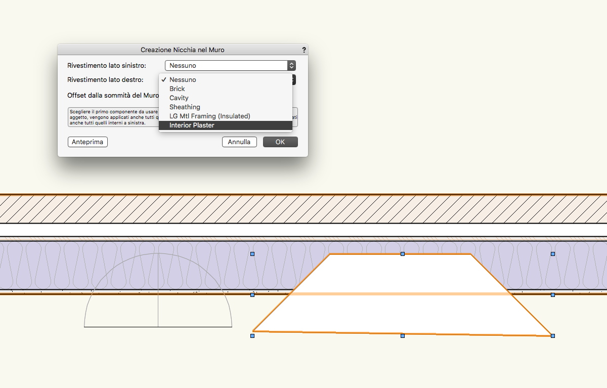
You need to control the wall style settings, the component and the design layer settings.
-
Hello everyone, I need to create a curved curtain wall with curved elements. At first I tried with the surface array tool, but it generate some non-curved elements. Same way with curtain wall tool. I know that theoretically I can manage it with a simple 3D model, but I need to know if it is really the only way. Specifically I need to create a portion of curved wall with few duplication Muratura_vetro_curva.vwx
-
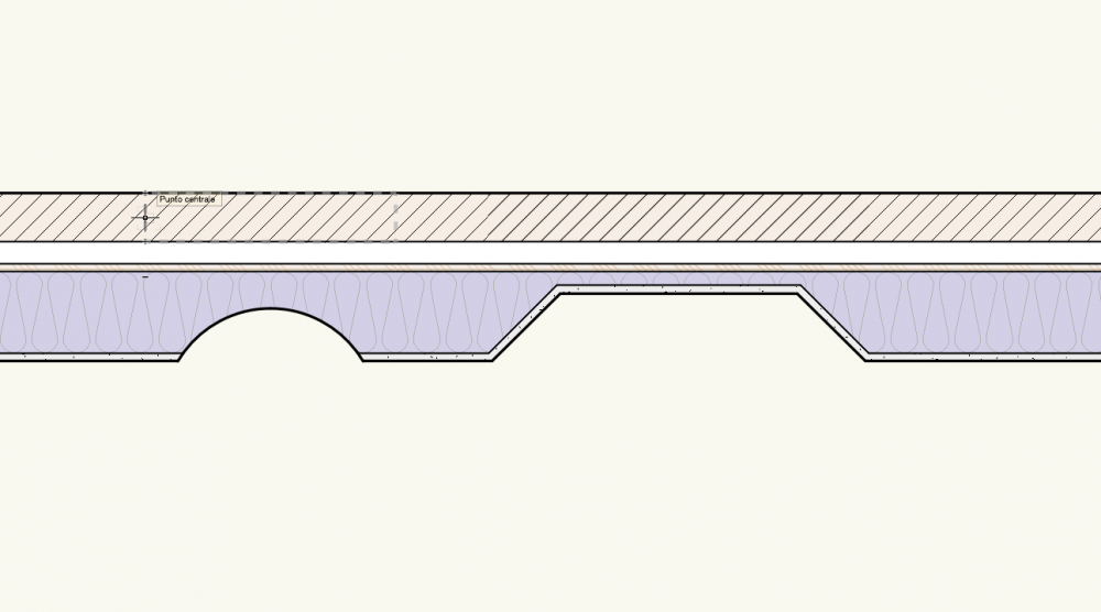
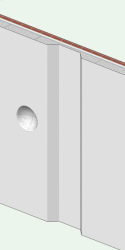
Roof-Wall component connection improvement
zeno posted a question in Wishlist - Feature and Content Requests
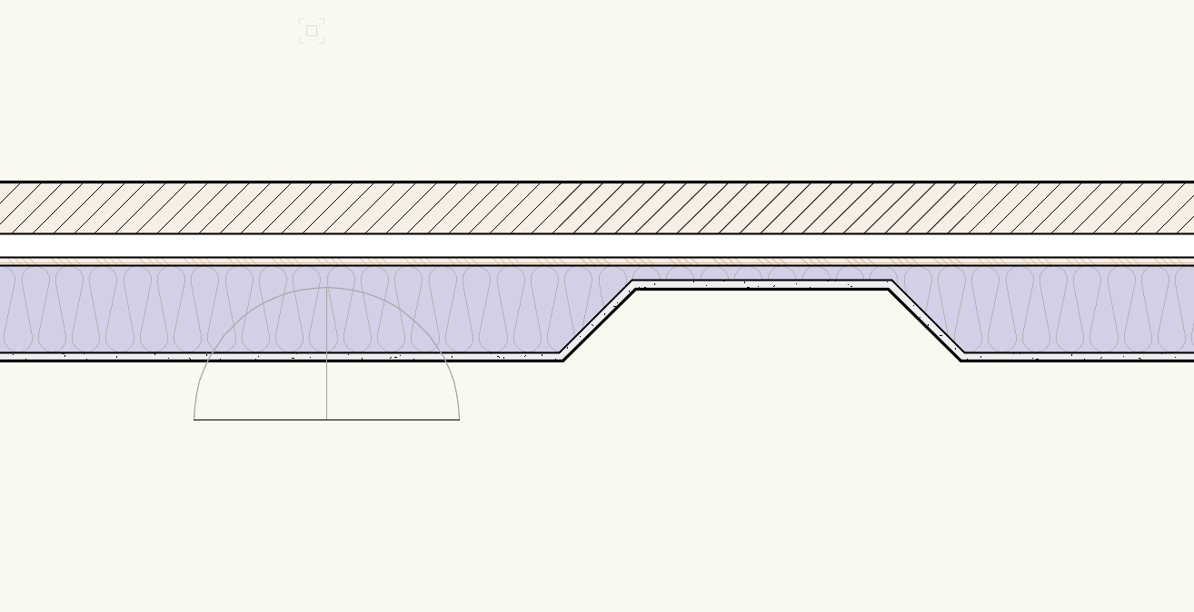
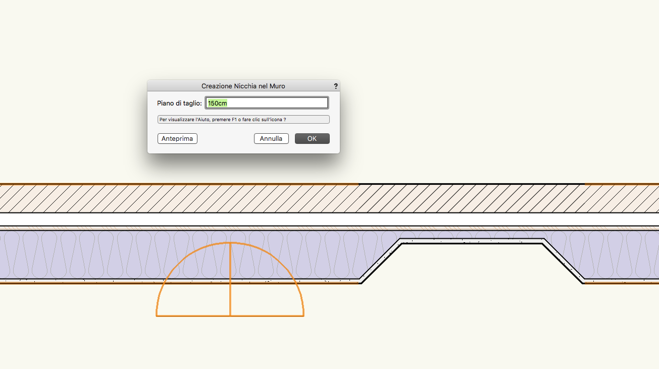
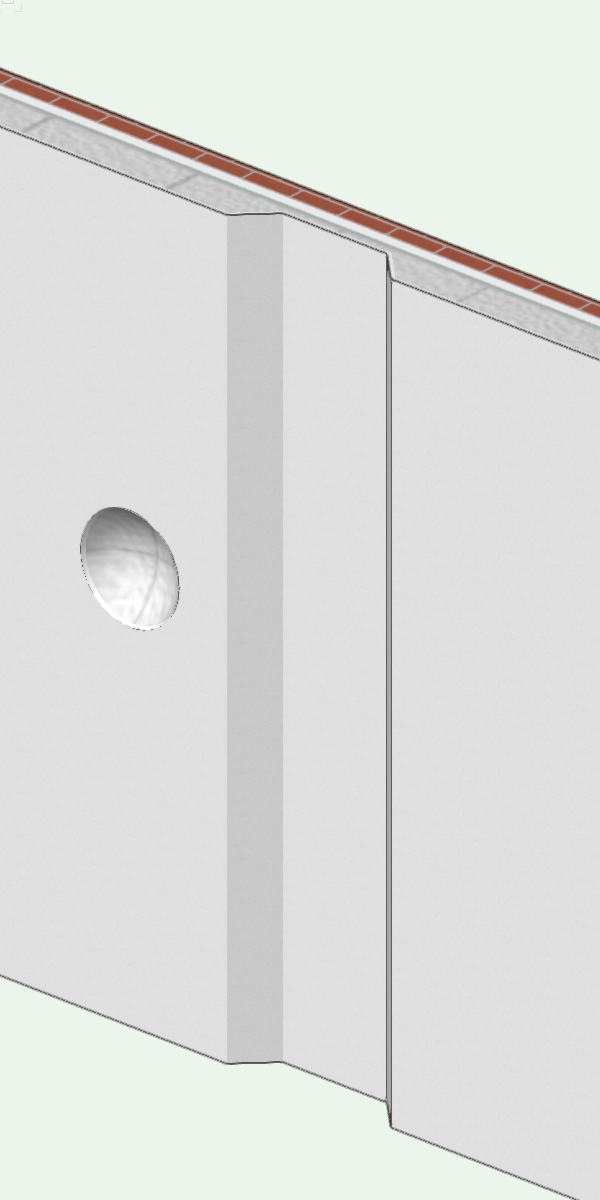
I'd like to see something allows us to manage correctly (yes.. like a real building, you know?) the connection between roof and wall components. Actually, I think it is almost difficult, and absolutely not BIM oriented. There are 3 problems. 1) The wall and the different thickness. I don't understand why, if actually, we can manage a slab component thickness for a slab, we can't do it for a wall. 2) Modify a wall in YZ plane, not only in XZ plane or in XY plane. Actually, we can add and remove picks, manage its height only in 1 direction. If we cut a wall in plan view, we can do it and the wall is still a wall. But: if we do this in a front view, it becomes a section solid, losing all the wall propriety. 3) In 2018 version, one of the better improvement is the possibility to manage the component between connected wall. Not in the same easily mode, but we can manage it between wall and slab. But, between wall and roof is impossibile. Could an Architecture BIM software not manage it easily? The building before all, I think. Seriously, sometimes I don't understand why in Vectorworks there are some unbelievable instrument, like surface array, and to connect a wall component whit a roof component (think about energetic management) is still a dream. I hope the attachment can help you to understand. And have a good work. I trust Vectorworks, but some improvement are ABSOLUTELY necessary.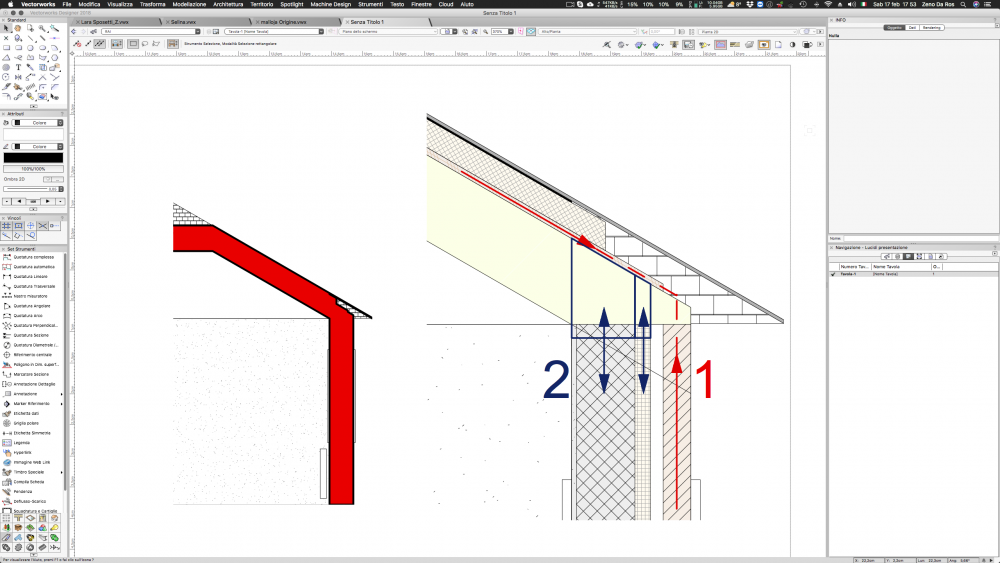
- 1 reply
-
- 1
-

-
I think that here and with viewport class overrides you can manage all correctly, without layers duplicating or increasing file's size. The most important question is that in a multi component wall ALL the attributes need to be assigned by class and you can manage it from navigation palettes. That's because is the only way to manage for example a new projected elements on a section viewport. There is no other ways to manage it. So the main rules in my opion is 1) existing wall styles with component all assigned by class like A_Wall-Ext_Comp-Plaster. The wall style name is WALL A 2) new wall styles with component all assigned by class like B_Wall-Ext_Comp-Plaster. The wall style name is WALL B 3) old wall styles with component all assigned by class like C_Wall-Ext_Comp-Plaster. The wall style name is WALL C The same work for door and windows. Always use a style. Then you manage all on the same viewport. I did so the work you can see on this post. The only problem is that I created something like 550 categories, with duplication and andvanced settings for group renaming (A-B-C for ALL components off walls, doors, windows and stairs). In fact now I'm working for a .sta file with them I can not go to be mad in my all day work. :-)
-
Thank you so much for your help. I have tried to create it with a 3D model or an irregular polyline, but it doesn't work.. it is correct?


-
Thank you! And don't worry! :-)
-
All one?
-
Remember that you can set the light, the reflection and the background from 3 different backgrounds.. but yes: in my opinion is better. You have a very good grass settings. May I ask if you could share some texture?
-
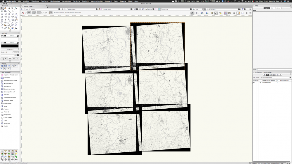
Hello everyone, i reopen this old topic because i have an issue about this argument i have already imported some TIFF files with .tfw references, but every image have a black background (see attachment). How could i remove it?
-
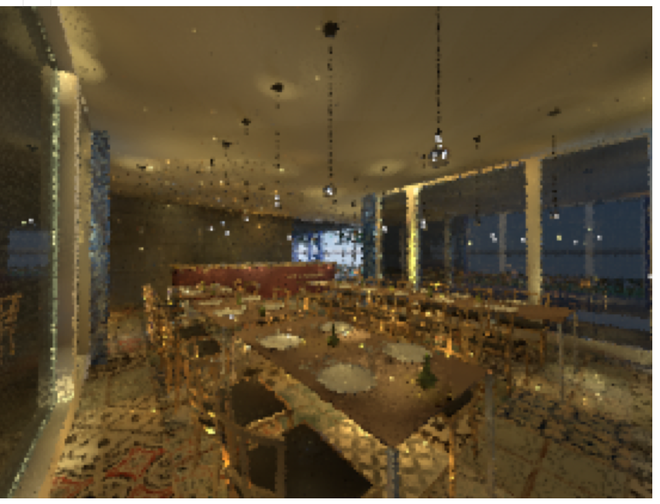
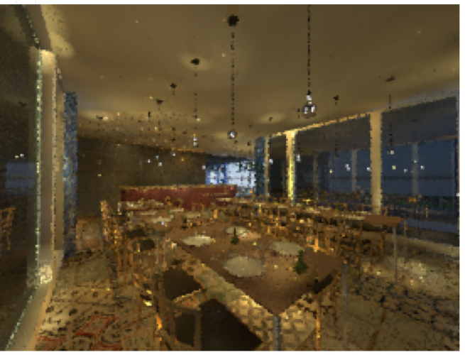
Try to activate the indirect light, 4 rebounds for external maximum 8, add an hdri background
-
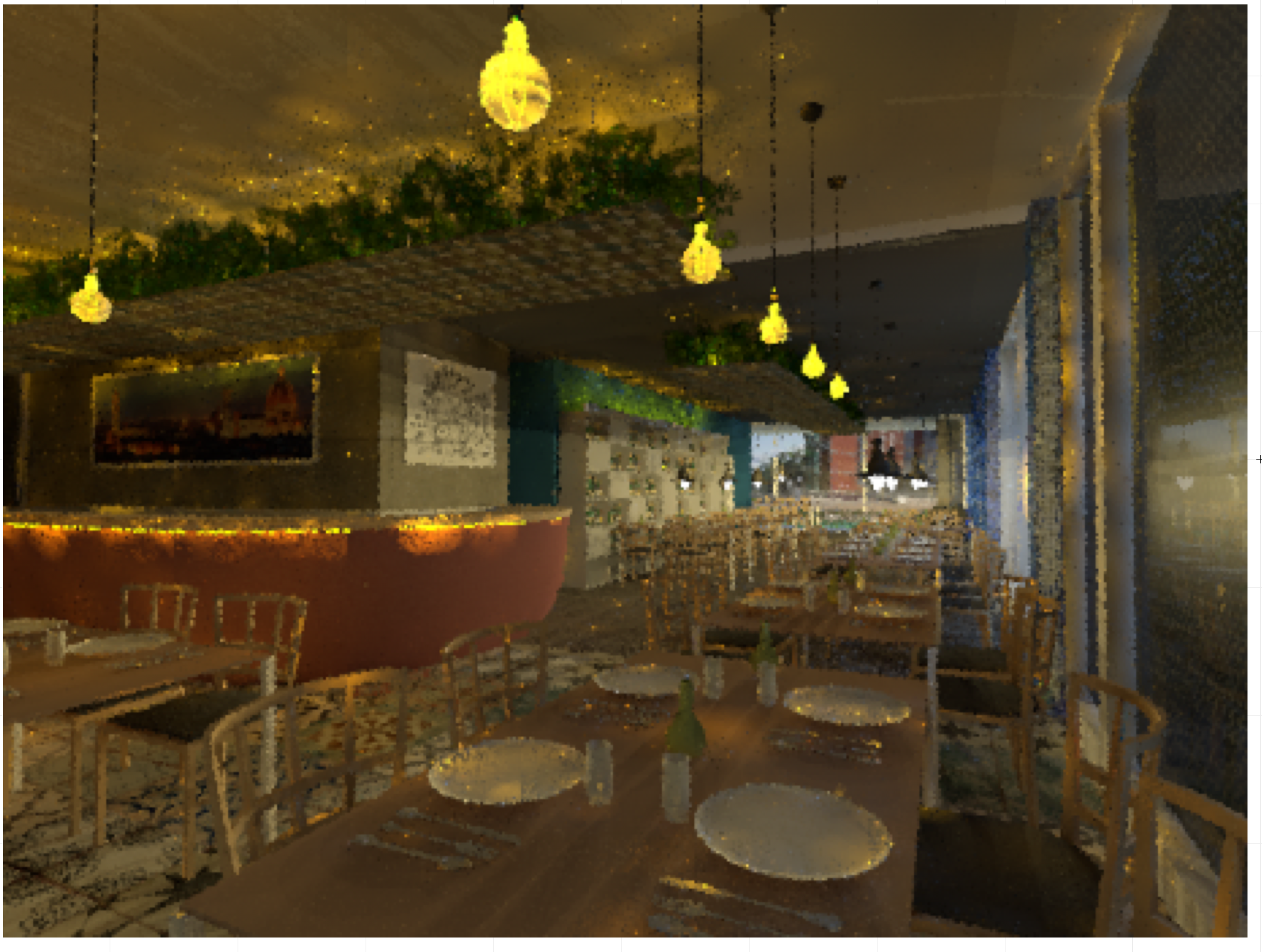
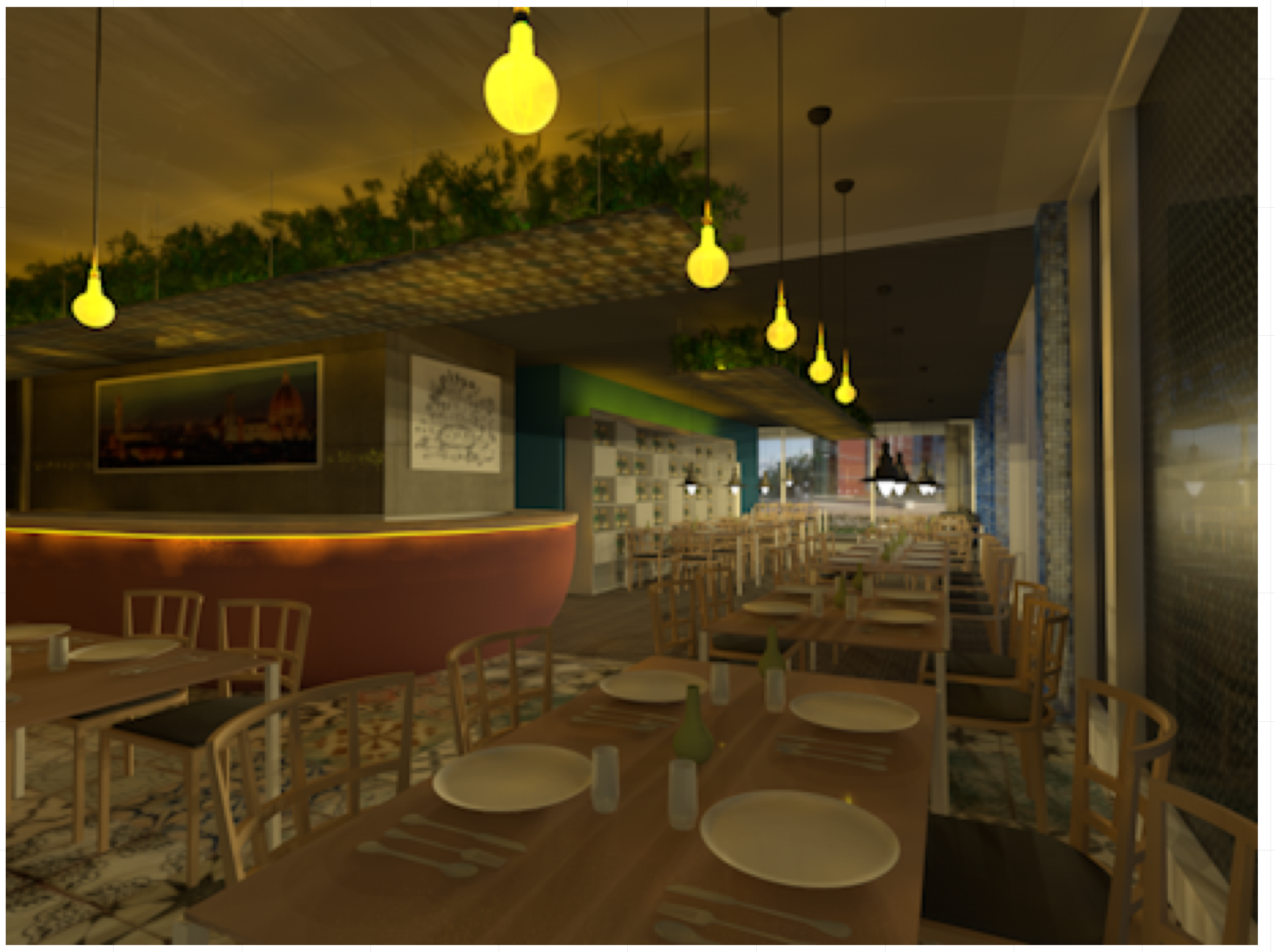
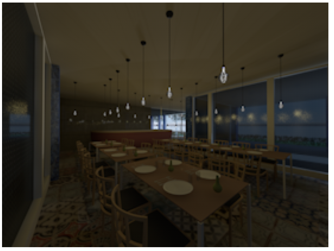
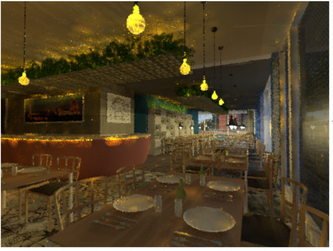
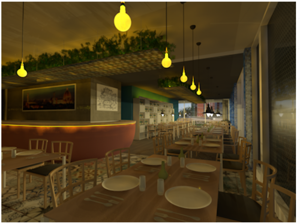
In fact, fast interior render default style has only 4 rebounds. Indirect lightning is too important, I mean, for give a realistic interior scene. Yes: some texture are set to Glow, but for the moment I turned off the background, replace it with 2 big photos-texture with retro-illumination set to 20% and increase some glow power in the scene. The result is better for now (the resolution is very low, I'm in a trying phase, maybe I will post later or tomorrow the final results)
-
Hello everyone I started yesterday a new work, and for now I'm trying new views in very very low resolution. But It is possibile to have too many differences between a fast and accurate rendtrworks style for internal view? They are the 2 default render style's system. Exept for quality, the only big difference is the rebounds Thank you all

-
Uu nhuoc diem dung may tinh Laptop Dell gia re
zeno replied to christinalevinee's topic in General Discussion
I use Space Navigator since 2013 version. It always work well. Be sure of 1) correct driver in installed (than you can see a blu light on space nav) 2) try it in Vectorworks walkthrough mode 3) try to adjust some settings. If necessary, add the application from OS system preferences -
Flat transparency, at layer or viewport level, rather than textures
zeno replied to Christiaan's topic in Rendering
You should find the 3D symbol model in resource browser, duplicate it, assign a specific render texture and set the opacity on the texture settings. After that, you replace the specific symbol whit the transparent copy