pclary
-
Posts
41 -
Joined
-
Last visited
Content Type
Profiles
Forums
Events
Articles
Marionette
Store
Everything posted by pclary
-
Andy, Thank you! I'm trying it now. Peter
-
So, some how I seem to have fixed that. But can anyone tell me ow to correct a link for a text field? I need to change my 'Sheet Title' from 'S_SHEET TITLE" to 'Sheet Title_SN' but I can't figure out how to access the records Thanks
-
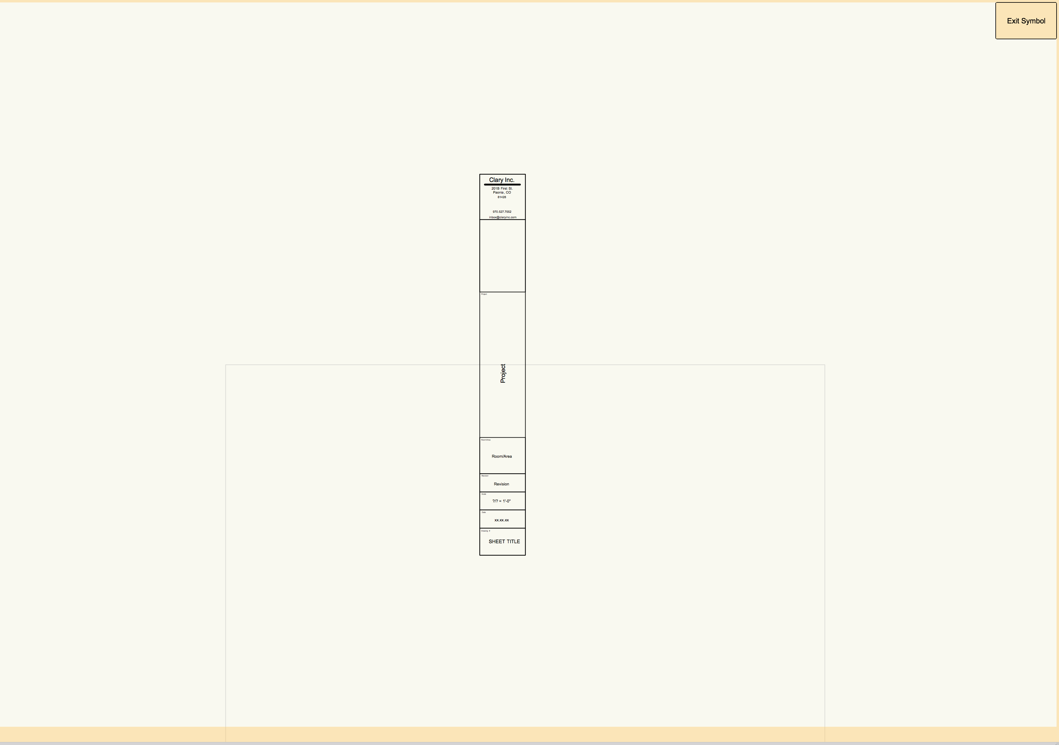
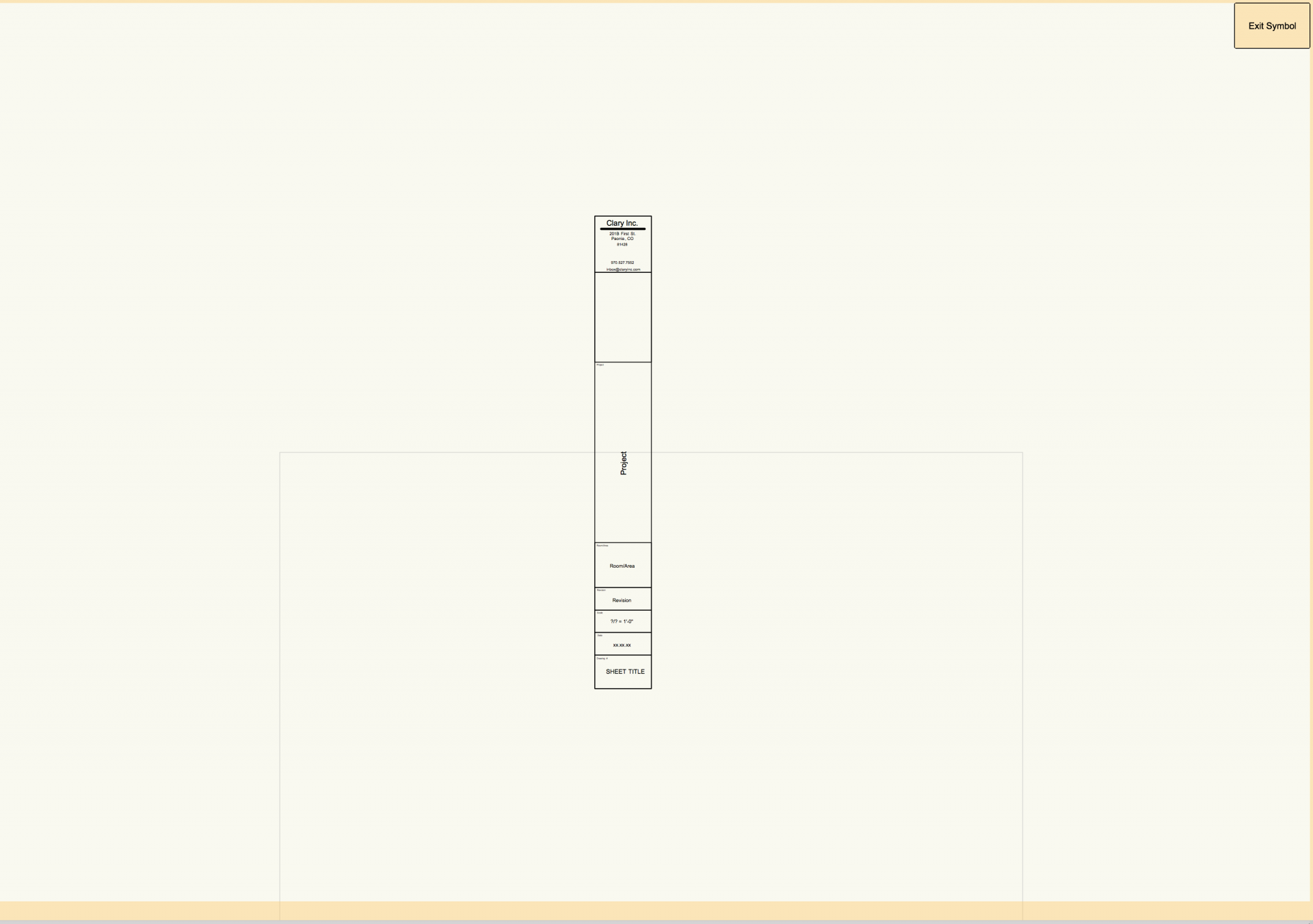
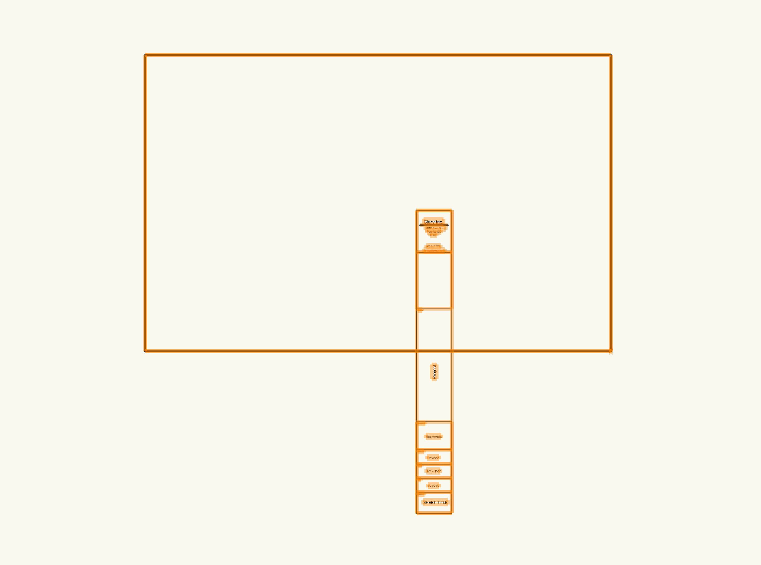
I had a working title block that would position correctly and data fields would fill in correctly. Had to get a new computer and somehow messed up the title block. So, decided to start from scratch and make a new one. I followed video tutorial in KB. After much trouble, got it working but the titleblock comes in positioned wrong. I tried editing it in Resource Manager but just can't get it. Hard to see in this screen shot but the title block is positioned with lower right corner on the 0,0 crosshair. But when I insert it, it comes in displaced: any help would so appreciated.
-
Jim, Just realized I didn't really answer your question. i don't normally look at the mode. I just do the keyboard shortcut and pull. If I hit the push/pull from the tool set at left, it shows I'm in the second mode. I just tried it again and although I see the red rectangle, it seems to be working. Must be me!. I'll keep watching. Thanks
-
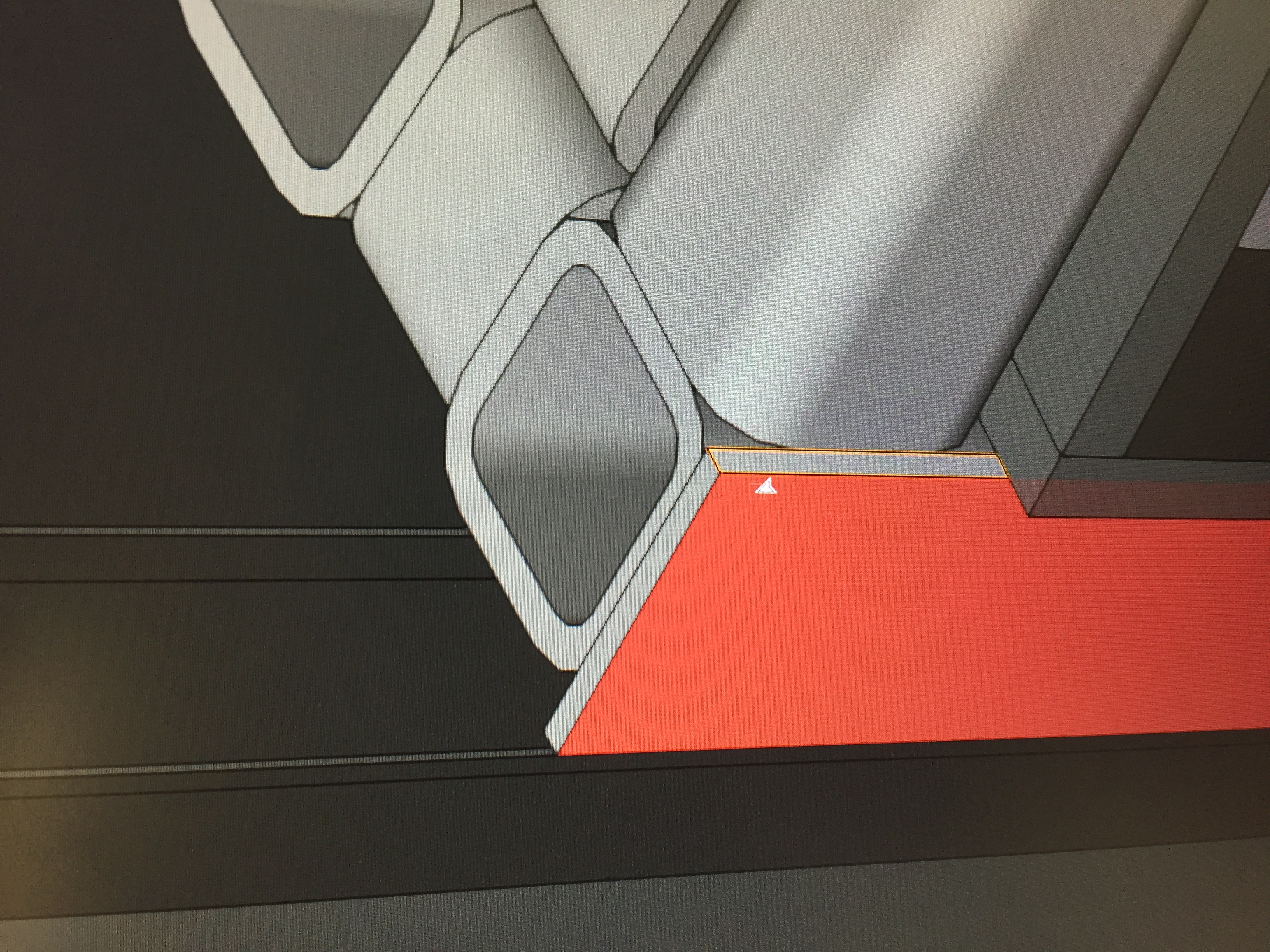
Jim, It's something I only just noticed in the last day or so. To try and answer your question more directly: When I use the push/pull tool on an already created face, it works just fine. The action in question arises when I draw a new face on top of another face (generally smaller) with the intention of push/pulling to create a new solid object. I hit the Shift-R keyboard shortcut and get the red rectangle at the cursor. The new face is selected but nothing happens. But if I go up to Extrude and key in a value, it extrudes just fine. Not sure what I'm doing wrong. I'll keep a better eye on the behavior unless you or someone has some input. Thanks,
-
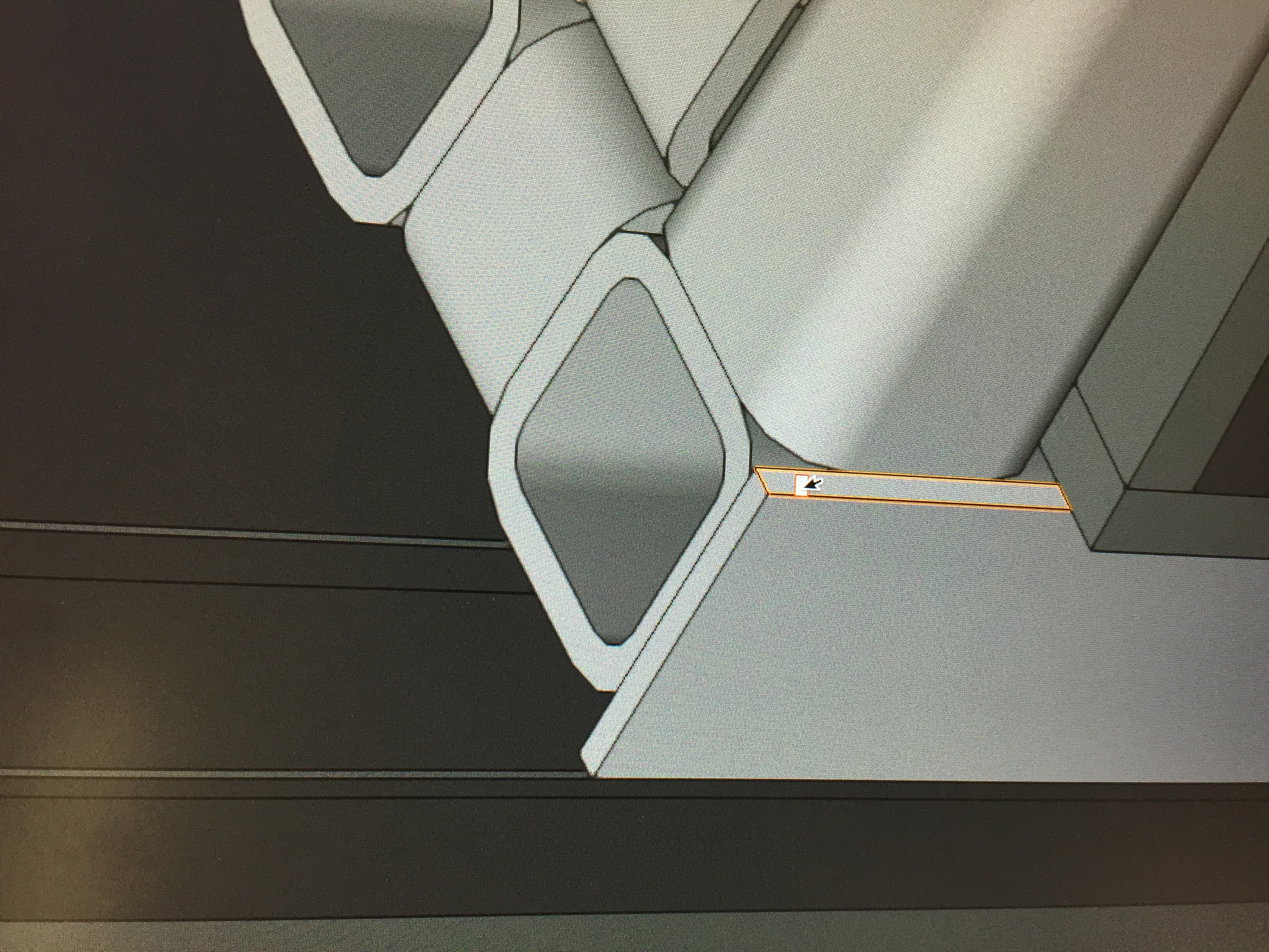
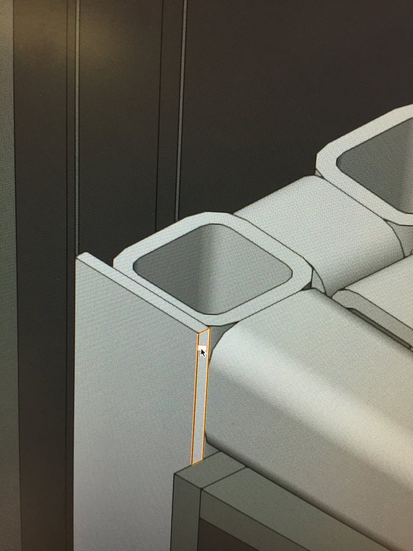
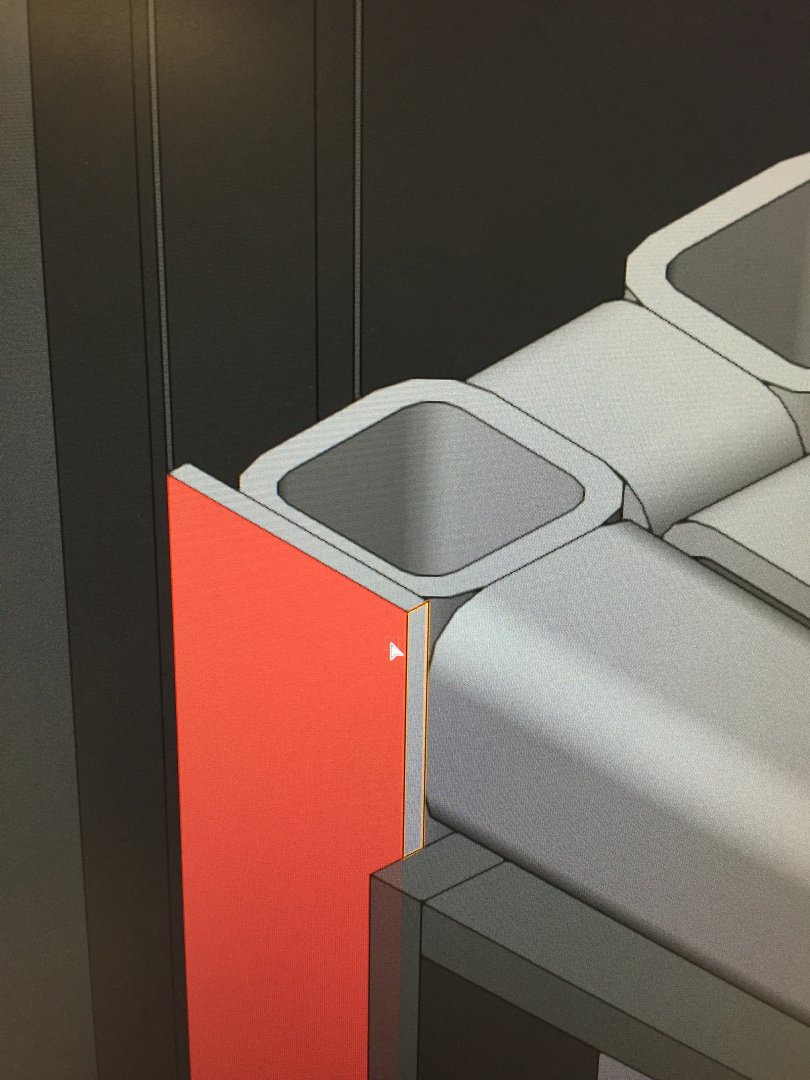
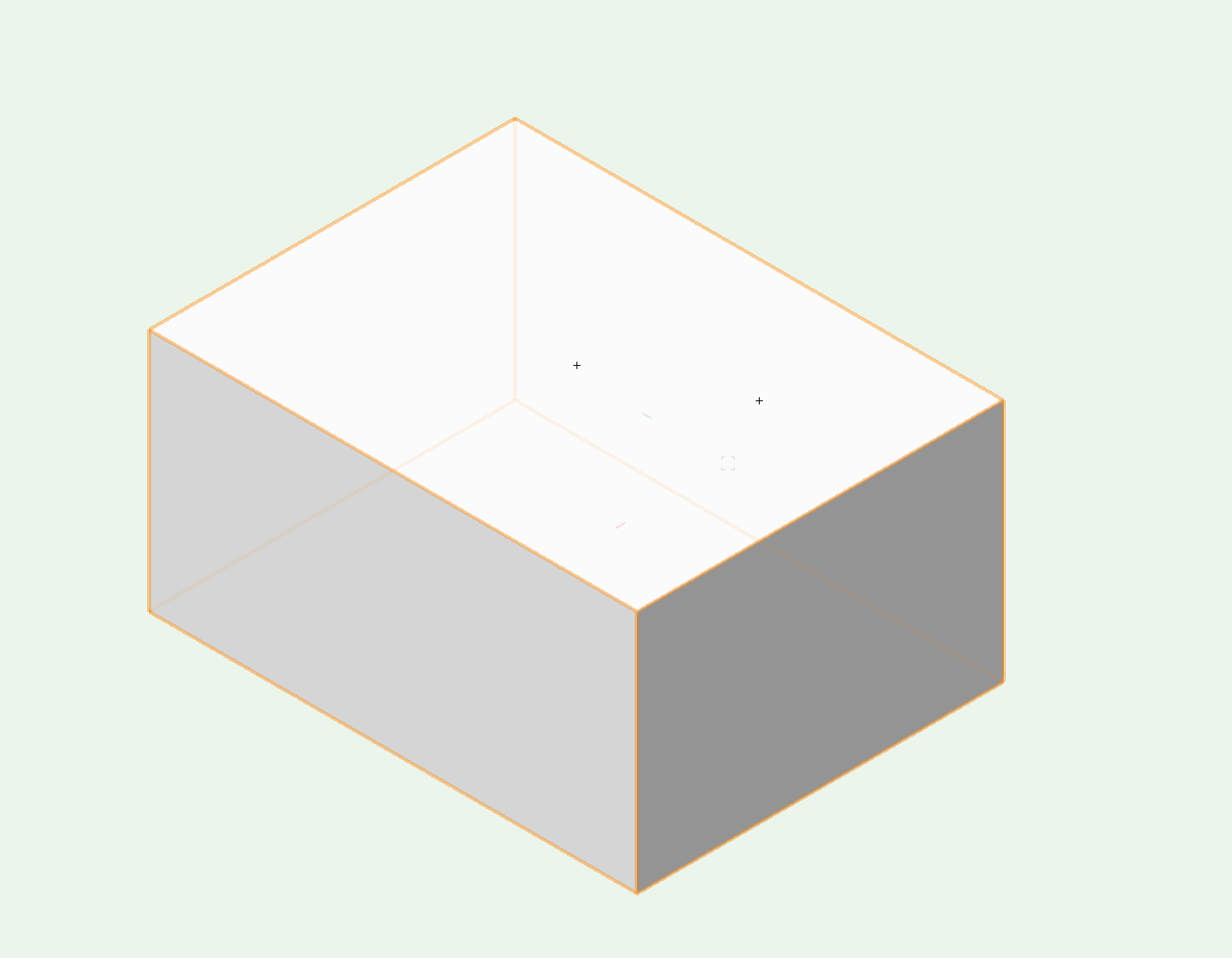
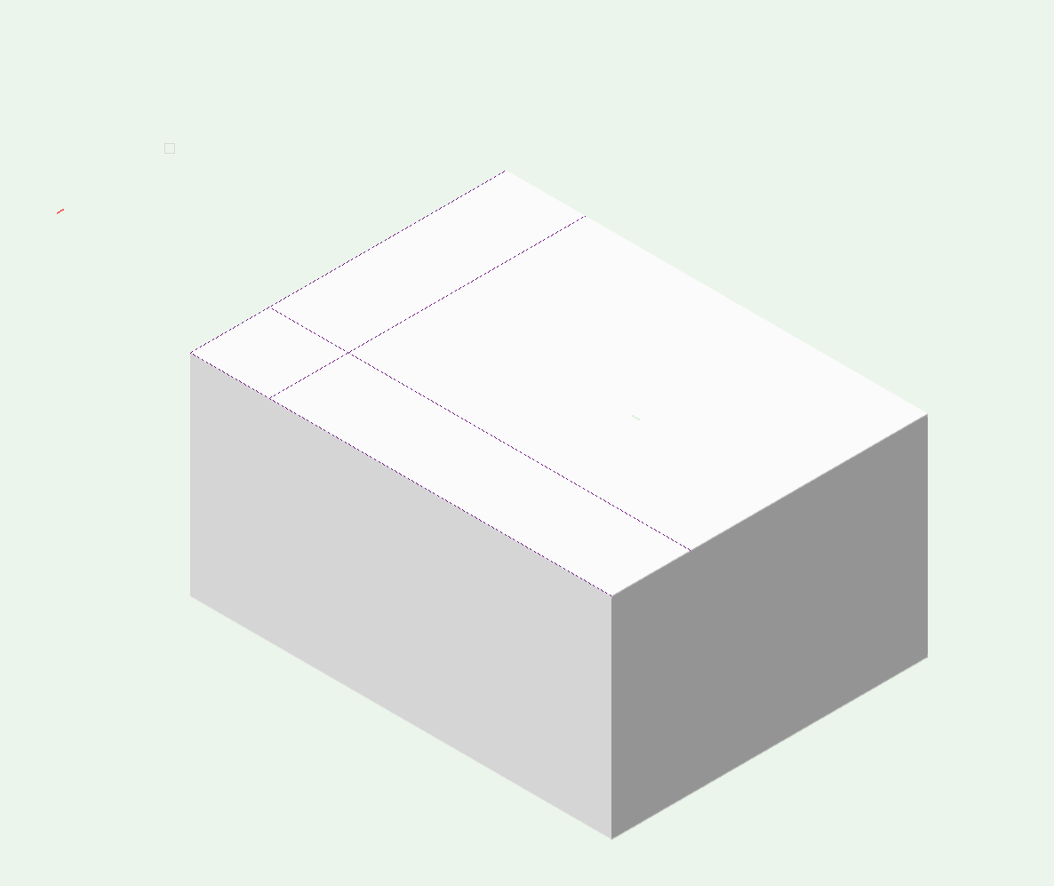
Can anyone tell me why I get a red rectangle @ my cursor sometimes when I want to do push/pull(see attached first image). If I move the cursor to an adjacent face on another object, I get the expected highlighting of that face for the push/pull operation. In the first case, I can still get what i want via the Extrude command under Model. In this case, I have draw the highlighted rectangle on the edge of the strip with the intent of creating another strip running perpendicular to the first one. Thanks
-
Answered my own question: I forgot I had simply renamed one document to a new name and had deleted the model. The Sheet layers stayed behind.
-
I have two documents going: Door 112 and Door 113 with models in both documents. I have made my viewports on several sheet layers for Door 112 and all is well. I went to my other document: Door 113 and started making viewports and sheet layers within that document. Q: when I go up to the Layers pulldown menu, I see all the sheet layers for Door 112 while I am in Door 113. Is it normal to see sheet layers from a different document? Both are in my VW window with tabs. Thanks
-
Didn't realize you could do that. I'll try it. Thanks
-
Thanks Alan, I was starting to doubt myself!
-
Thank you Benson! I was getting 'agitated' at my inability to make it work. I gave up for the night. Try again tomorrow. Peter
-
Alan, I don't want to overstay my welcome. But I can't make the automatic working plane work if I'm inserting a fastener. i don't know you do it. I use the back slash key and if I'm drawing a rectangle or a circle, it works like a charm. but if I have my block, hit back slash, hover over a face, the face selects but as soon as i click on the fastener tool, the Layer Plane is selected.
-
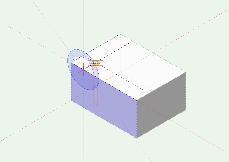
Thanks. i guess I don't know how to explain my question adequately. I now see how to snap the fastener to a point but I'm still wondering if my rotate process is correct. If so, I guess the answer to a previous question about is there a way to insert a fastener normal to a face upon insertion, is no. I appreciate your help
-
Thanks for all the help Alan. I guess I am doing it correctly. So in your last video, to get the eye bolt normal to the surface, would you then use the rotate tool and select the correct face to use as a plane to rotate in?
-
okay, I just tried that but the bolt still goes to another plane am i doing the whole process wrong or is it a multistep thing of inserting, then moving, then rotating?
-
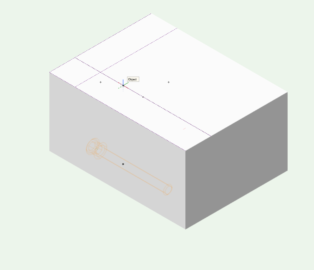
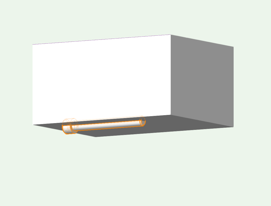
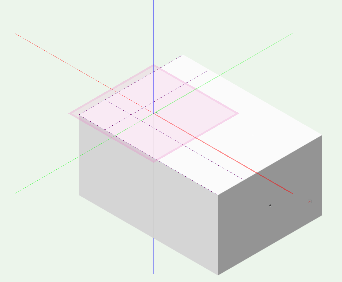
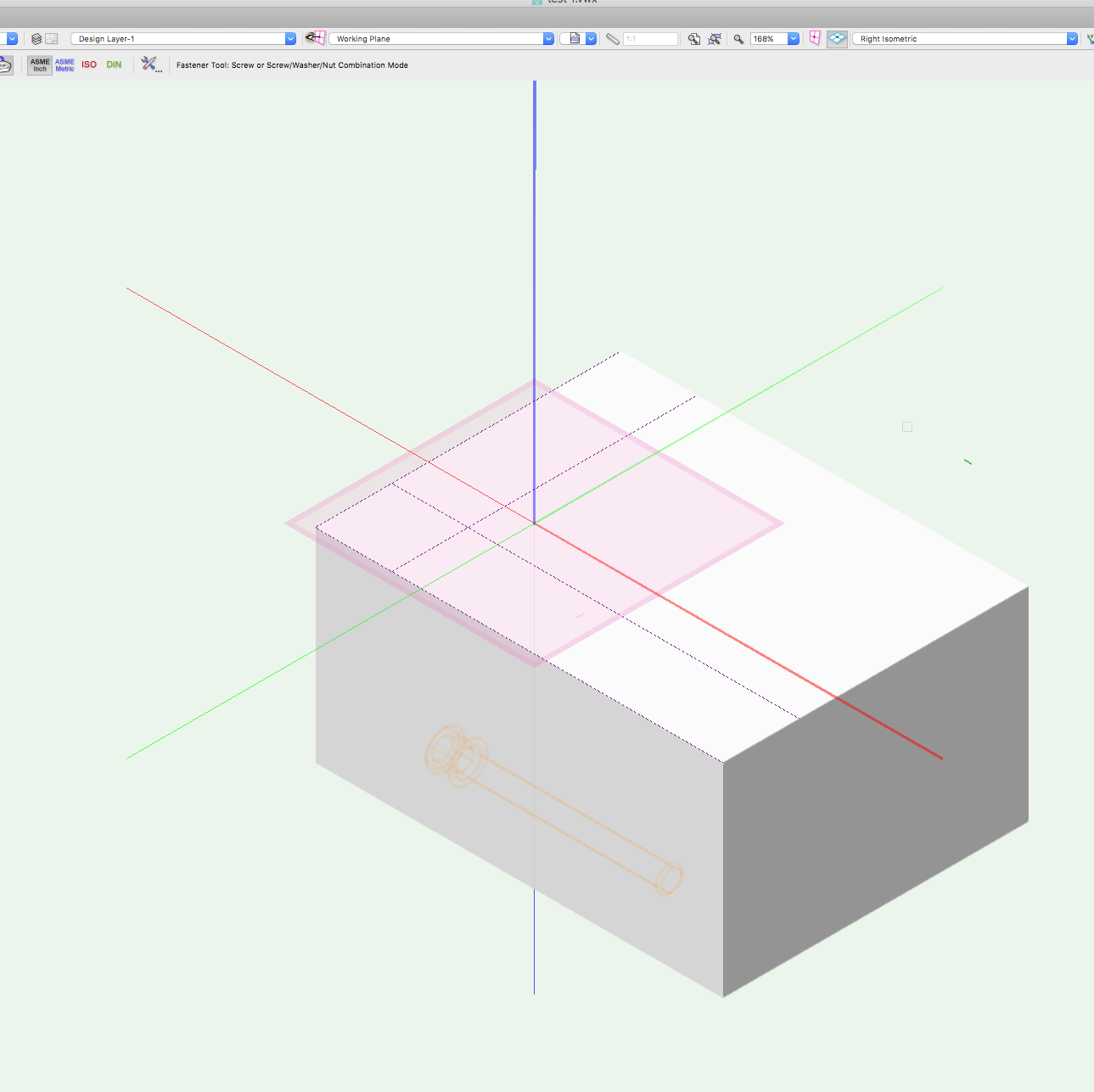
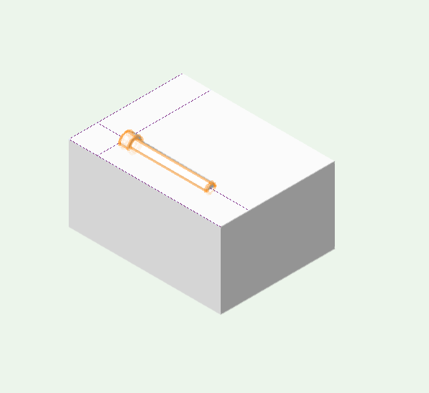
Alan, I end placing fasteners in a lot of the models I do in order to show the architect and the shop how I want things connected. Here's some screen shots of a simplified process that I end up doing: 1. create object 2. locate location where fastener is wanted 3. get fastener, select 3D, click on cross hair to insert 4. fastener shows up on another face than where I clicked and dragged 5. I tried setting a working plane on the top face of the block but get same result 6. I can go get the bolt and drag it up to the desired insertion point, 7. then rotate it by using the correct face and the rotate tool. it seems like a lot of steps to get a fastener inserted. Is there another way? Or is this the correct process? In your video, you bring the symbol (the bracket) into the model, then you place it. Thanks for any help, Peter
-
Alan, Thanks for the video. I'll try it and see what I can do and if I have trouble will reply again. I think that one snap setting may have been making it hard. Peter
-
Benson, Yes, I have been using the automatic mode. But I'm still having trouble getting the results I want so sometimes I set a working plane. I haven't tried symbols yet. In this case, I'll probably never draw this bracket again as it's a one off solution to a problem. But the gist of my post was how to easily insert a fastener at a certain location and with the proper orientation. On the bracket in the screen grab, I want a fastener at the intersection of the white guide lines on the three tabs of the bracket. Sometimes the fastener inserts at the proper location, but often it's down on the Layer Plane, even if I've set a working plane on the face of the bracket. then i have to move it up into place. Then I have to rotate it. is there a way to have the insertion point be where I click on the part? And to have it insert normal to the face? Thanks
-
Benson, I see what you're suggesting but if I had done that, why would the objects toggle their visibility when I clicked on the their class visibility from Nav pallet while in the model? I'm guessing I did something wonky and now know what to do if I do it again. But I think something else happened. My sheet layers from one model showed up on another model. And I can't get them back. I also couldn't get the paper size to switch to tabloid. Also, title block wouldn't show. I'm redoing all viewports and sheet layers. So far it's all working as expected. Your tip re selecting similar is good, would've saved time. Q: In a tutorial from Sean O'Skea, he suggested to turn off autosave during viewport creation -->That VW could get wonky. Is this something to be aware of? I'm using 2017 and his tutorial was for an earlier version I think. Thanks
-
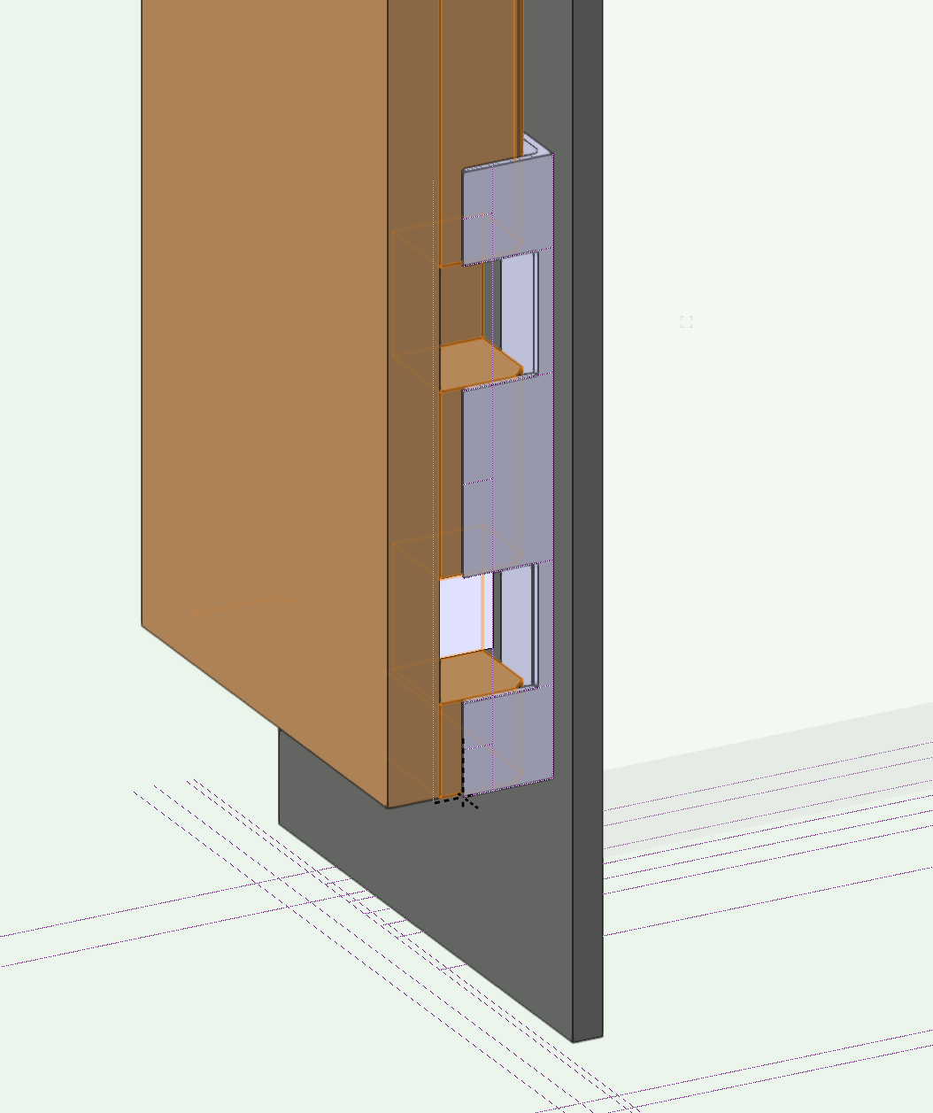
Pat, As a brief explanation: I am modeling a steel jamb for a large door in a residence. I had my field dimensions of where the framing, subfloor, stone work, plywood surfaces are and their dimensional relationship to each other. Starting in 2D Plan view, I 'drew' these elements then switched to Iso view and pulled the studs up etc. I covered the walls in plywood and added in the stone work. These objects were mostly drawn with the rectangle tool, switching the Active Class as I created the different items. Occasionally, Items were created in the wrong class but this was corrected via the OIP. Visibility was toggled on/off as I went via the Navigation Pallet. The model was done and all objects were in their own class. I didn't use any groups or symbols. At least not intentionally! I then went to create my drawings for submittal and created viewports on different sheet layers. I started having trouble getting the viewports to show only what I wanted. I was concerned that I was having GPU issues so I shut down VW, rebooted the computer ( 2014 MacBook Pro, running 30" Cinema display). No help. Closed all other programs. Looked at other models and their sheet layers. All was as I wanted. The issue: In my door jamb model, the Framing, Plywood, Durock (stone substrate) classes were set to invisible. The model displayed correctly. In the viewports that were created right from the model in the wanted setup, objects were visible that should not have been: The 'Framing' class was marked invisible. As was the plywood and Durock. But I could still see them in the viewport , even thought they weren't visible in the model. I checked the classes in the viewport OIP and they should have been invisible. I was looking at the navigation pallet and saw that the current class was the None class. I don't remember putting anything in that class. So, in the model, the framing etc toggled visible/invisible as would be expected as I checked/unchecked the class visibility . But in the viewport, it made no difference. Finally, I clicked on a piece of framing, looked at the OIP and it said None. What?!?! Same for all the other objects that visible when they shouldn't have been. At least from the Class visible/invisible selections. I corrected the class for each 'stuck' object and now viewports are only showing what I want. So, I assume that somehow I linked these already classed objects into the None class. I don't know how I would have done that. Any thoughts/ suggestions? Thanks, Peter
-
So, I think I figured it out: the objects that were showing up were somehow in two classes. Is that possible? i.e.: in my model there are 2x8 framing objects that were assigned the class 'Framing'. Same for plywood, durock... They were created by class when I made the model. But when I go to the model and select them, they show up as being in the 'None' class in the OIP. But if I change their visibility (i.e.: Framing) via the navigation palette, they show/not show as expected. I re-classed them and now the viewport shows what I want and not what I don't. Q: How did I screw up the class for these items? And how did they seem to be in two classes? Thanks
-
Something new and odd for me: in my model, I have turned off all classes that I don't want to see in a new viewport. I create a viewport as usual, but when I look at that viewport on the new sheet layer, what should be non visible classes are showing up. I've checked the class visibility for that viewport and everything is as I want. I update the viewport but still it shows unwanted classes. If I make non visible, the classes of the wanted objects, then update, then disappear as expected. But not for the unwanted ones. If I grey the unwanted classes, they change but I can't make them non visible in the viewport, even thought they are in the model. Any help would be appreciated Door__112.vwx
-
Hi, I could really use a step by step tutorial for how to place a fastener in a certain location and with the proper orientation. I have been doing it in a hap hazard way with rotations, moving of fasteners etc. It's really slow and frustrating. I assume I do it the wrong way. I have an object, in this case a bracket, have located the position where I want the fastener inserted using guide lines. Sometimes it is placed at the desired insertion point, sometimes down on the layer plane. Almost always rotated. I have read the Help post about how to do it but I can't seem to make it work. A screen grab is attached with guide lines showing the desired insertion point. Thanks
-
Matthew, Thanks for the reply. No, I didn't use 'Publish' as I didn't know about it! But I'l look into it (ultra newbie) I just started going back through each drawing and was fixing them by re-doing the sheet border and title block. I did a few and Wowza! the borders and title block are back! But in terms of proper workflow: I made the model, created sheet layers with viewports, printed as I went to verify it's all good. The model was being saved automatically very 5 mins. Am I right in thinking that this is the correct way to work? And that I can at any time go back into the file and see the sheets with borders and title block? And reprint copies? And only save the model not each sheet ? Thanks